EP0470627A1 - Transfer system - Google Patents
Transfer system Download PDFInfo
- Publication number
- EP0470627A1 EP0470627A1 EP91113364A EP91113364A EP0470627A1 EP 0470627 A1 EP0470627 A1 EP 0470627A1 EP 91113364 A EP91113364 A EP 91113364A EP 91113364 A EP91113364 A EP 91113364A EP 0470627 A1 EP0470627 A1 EP 0470627A1
- Authority
- EP
- European Patent Office
- Prior art keywords
- pallet
- air table
- air
- guide
- linear motor
- Prior art date
- Legal status (The legal status is an assumption and is not a legal conclusion. Google has not performed a legal analysis and makes no representation as to the accuracy of the status listed.)
- Granted
Links
Images


Classifications
-
- B—PERFORMING OPERATIONS; TRANSPORTING
- B65—CONVEYING; PACKING; STORING; HANDLING THIN OR FILAMENTARY MATERIAL
- B65G—TRANSPORT OR STORAGE DEVICES, e.g. CONVEYORS FOR LOADING OR TIPPING, SHOP CONVEYOR SYSTEMS OR PNEUMATIC TUBE CONVEYORS
- B65G49/00—Conveying systems characterised by their application for specified purposes not otherwise provided for
-
- B—PERFORMING OPERATIONS; TRANSPORTING
- B65—CONVEYING; PACKING; STORING; HANDLING THIN OR FILAMENTARY MATERIAL
- B65G—TRANSPORT OR STORAGE DEVICES, e.g. CONVEYORS FOR LOADING OR TIPPING, SHOP CONVEYOR SYSTEMS OR PNEUMATIC TUBE CONVEYORS
- B65G54/00—Non-mechanical conveyors not otherwise provided for
- B65G54/02—Non-mechanical conveyors not otherwise provided for electrostatic, electric, or magnetic
-
- B—PERFORMING OPERATIONS; TRANSPORTING
- B65—CONVEYING; PACKING; STORING; HANDLING THIN OR FILAMENTARY MATERIAL
- B65G—TRANSPORT OR STORAGE DEVICES, e.g. CONVEYORS FOR LOADING OR TIPPING, SHOP CONVEYOR SYSTEMS OR PNEUMATIC TUBE CONVEYORS
- B65G35/00—Mechanical conveyors not otherwise provided for
- B65G35/06—Mechanical conveyors not otherwise provided for comprising a load-carrier moving along a path, e.g. a closed path, and adapted to be engaged by any one of a series of traction elements spaced along the path
-
- B—PERFORMING OPERATIONS; TRANSPORTING
- B65—CONVEYING; PACKING; STORING; HANDLING THIN OR FILAMENTARY MATERIAL
- B65G—TRANSPORT OR STORAGE DEVICES, e.g. CONVEYORS FOR LOADING OR TIPPING, SHOP CONVEYOR SYSTEMS OR PNEUMATIC TUBE CONVEYORS
- B65G51/00—Conveying articles through pipes or tubes by fluid flow or pressure; Conveying articles over a flat surface, e.g. the base of a trough, by jets located in the surface
- B65G51/02—Directly conveying the articles, e.g. slips, sheets, stockings, containers or workpieces, by flowing gases
- B65G51/03—Directly conveying the articles, e.g. slips, sheets, stockings, containers or workpieces, by flowing gases over a flat surface or in troughs
Definitions
- the present invention relates to a transfer system for transferring a load such as a heavy object to be processed, and a transfer pallet on which the load is placed.
- Figs. 27 to 31 show transfer systems known in the art.
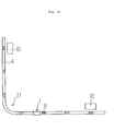
- a conventional transfer system includes a truck 1. 2 is a table connected to a truck body 3 by a vertical support 2'. 6 are wheels rotatable about a horizontal shaft which is mounted to the truck body 3. 4 is a guide of a U-shaped cross section. 5 are a pair of rails fixed to the inner walls of the guide 4. The wheels 6 of the truck 1 are supported on the rails 5. 7 are wheels each rotatable about a vertical shaft which is connected to the truck body 3. The wheels 7 are in contact with the inner side walls of the guide 4. 8 is a secondary conductor of a linear motor.
- Figs 30 and 31 show another transfer system known in the art.
- 14 is a base.
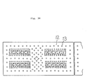
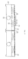
- 15 is an air duct seated on the base 14.
- 12 is a top plate of the air duct 15.
- 13 are a number of nozzle holes formed in the entire surface of the top plate 12.
- 16 are linear motor primary coils mounted within the air duct 15.
- 17 is a pallet including a linear motor secondary conductor on its lower surface.
- 18 is a pressurized air supply source.
- the base 14 and the air duct together form an air table. Air under pressure is supplied from the pressurized air supply source to the air duct 15 and then injected from the nozzles 13 to float the pallet 17 together with a load above the top plate 12 of the air duct 15.
- the pallet 17 together with the load is transferred from one station to another station when the linear motor primary coils 16 are energized.
- a transfer system employs a pallet to carry a light load of several kilograms to several hundred kilograms.
- the pallet together with the light load is floated on an air table and moved by a linear motor as shown, for example, in Figs. 30 and 31.
- the table 2 is attached to the truck 1 by a single post or support 2'. This causes the table 2 to swing and move out of alignment with the guide 4. Thus, a load on the table can not be moved in parallel to the guide 4.
- the section 11 of the guide 4 has a small radius of curvature, a pair of front wheels 6, the four wheels 7 and a pair of rear wheels are oriented as shown in Fig. 28. This inhibits a change in the direction of movement of the truck 1.
- the guide 4 is constructed in a factory so that the section 11 may have a large radius of curvature. This deteriorates systematic arrangement of the transfer system.
- the truck 1 can not be stopped in a predetermined position. This deteriorates the operability and safety in a production line.
- a large pressurized air supply source is required to inject air under pressure from a number of nozzle holes 13 of the air duct (or air table) not only before each pallet 17 passes, but also after the pallet has passed. This results in an increase not only in the cost of the system, but also consumption of the pressurized air and thus, running cost of the system.
- a pallet In the prior art transfer system incorporating the air table and the linear motor, a pallet must be rigid and heavy to transfer a heavy load, for example, of several tons (about two tons) at a high speed (2 m/sec). To transfer such a heavy pallet at a high speed, it is necessary to increase size of the linear motor and the flow rate of pressurized air. However, this results in an increase in the overall size of the transfer system.
- a pallet is transferred to a press machine in a production or press line while being floated by air under pressure. A force is then applied to press a load on the pallet.
- the pallet must be rigid to accommodate this force. This results in an increase in the weight of the pallet.
- To transfer such a heavy pallet it is necessary to provide a larger linear motor and increase the flow rate of air under pressure. This results in a corresponding increase in the overall size of the press system.
- Another object of the present invention is to provide a pallet which is lightweight and which can reduce the size of a linear motor and the flow rate of air under pressure and thus, the overall size of a transfer system designed to float the pallet above an air table and move the pallet by the linear motor.
- the pallet is placed on the air table, and a load is placed on the pallet.
- the ball valve located immediately below the pallet, is opened to apply air under pressure to the pallet.
- the primary coils are then energized to accelerate the floating pallet.
- the pallet is moved to a station while being guided by the guide. When the pallet reaches the station, the primary coils are energized to reduce the speed of the pallet, and the pallet stoppers are operable to stop the pallet.
- the pallet is thereafter moved to a next station after the work on this station is completed.
- the pallet is placed on the air table, and a load is placed on the pallet. Air under pressure is applied from the ball valves to the pallet.
- the acceleration primary coils are then energized to accelerate the floating pallet.
- the guide rollers and the grooved guide cooperate to guide the pallet.
- the deceleration primary coils are energized to reduce the speed of the pallet.
- the pallet stoppers are then operable to stop the pallet.
- the guide roller mounted to the inner front of the pallet is moved into the grooved guide through a recess.
- the acceleration primary coils mounted to the turning section of the air table are energized to accelerate the pallet.
- the guide roller mounted to the inner rear of the pallet is moved out of the grooved guide through a recess.
- the pallet is placed on the air table, and a load is also placed on the pallet. Air under pressure is applied from the ball valves to the pallet. The acceleration primary coils are then energized to accelerate the floating pallet. The pallet is then moved to a certain station while the guide of the pallet is guided by the guides of the air table. When the pallet reaches the station, the deceleration primary coils are energized to reduce the speed of the pallet. The pallet stoppers are then operable to stop the pallet. After the load has been processed, the pallet is moved to the next or turning section of the air table in the foregoing manner. The pallet is again brought into contact with the pallet stopper and then stopped.
- the pallet is placed on the air table, and a load is also placed on the external load part of the paleet.
- the pallet together with the load is then lifted by air under pressure.
- the linear motor and the guides cooperate to move the pallet to a predetermined station.
- application of the air under pressure is prevented.
- This causes the pallet to be placed on the air table.
- the lower surface of the external load part projects slightly from the lower surface of the pallet body.
- the pallet body made from a light material is in no way contacted with the air table. Instead, the external load part made of iron or other metals is brought into contact with the air table to support the load. As a result, no external force (for example, pressing force) is applied to the pallet body.
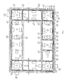
- Figs. 1 to 9 illustrate a first embodiment of the present invention.
- 26 is an air table or frame of a rectangular shape as viewed in plan.
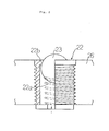
- 22 are a number of ball valves 22 formed in the entire air table 26.
- 23 is a ball in each ball valve 22.
- 22a is a spring disposed to urge the ball 23 toward a valve seat 22b to close the ball valve.
- 32 is a pallet.
- 24 are linear motor secondary conductors attached to the lower surface of the pallet 32.
- 25 is a base of the air table 26.
- 27 are linear motor primary coils mounted to the air table 26.
- 35 is a grooved guide provided on the outer periphery of the air table 26.
- 36 is a mounting plate adapted to fix the grooved guide 35 to the base 25.
- a guide roller 33 is mounted to each corner of the pallet 32 and rotated within the grooved guide 35.
- Figs. 1, 4, 6 and 9, 30 are pallet stoppers each provided at the front side of the 90 turning section of the air table 26 in the direction of conveyance of the pallet.
- Each pallet stopper 30 comprises a stopper plate 30a, guides 30b adapted to support retractable guide rods integral with the stopper plate 30a, and a shock absorber 30c disposed between the guides 30b and the stopper plate 30a.
- the pallet stoppers 30 are mounted to the base 25.
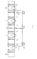
- Figs. 1 and 5 to 7, 28 are pallet stoppers centrally located in the air table 26.
- Each pallet stopper 28 comprises a retractable stopper plate 28a, guides 28a' adapted to support the stopper plate 28a, and a shock absorber 28b disposed between the stopper plate 28a and the guides 28a', a support table 28e adapted to support the guides 28a', a link mechanism 28c adapted to vertically move the support table 28e, and a drive cylinder 28d connected between the link mechanism 28c and the base 25.
- 29 are pallet stoppers cooperating with the pallet stoppers 30 and 28 so as to stop the pallet 32 in the 90 turning section and the intermediate section of the air table 26.
- Each pallet stopper 29 comprises an air motor 29a, and a wedge-shaped stopper arm 29b.
- the air motor 29a When the pallet 32 comes into contact with the pallet stoppers 30 and 28, the air motor 29a is energized to swing the wedge-shaped stopper arm 29b in the direction of the arrow shown in Fig. 9. This causes the wedge-shaped stopper plate to come into contact with the rear surface of the pallet 32 and cooperate with the pallet stoppers 30 and 28 to stop the pallet in the 90 turning section and the intermediate section of the air table.
- the air table has stations 31 provided at the four turning sections as indicated by C, D, G and H, and the intermediate sections as indicated by A, B, E and F.
- the pallet stoppers 30 and 29 are located at the front and rear sides (or upstream and downstream sides in the direction of conveyance of the pallet) of each of the turning sections C, D, G and H of the air table 26. Also, the pallet stoppers 28 and 29 are located at the front and rear sides of each of the intermediate sections A, B, E and F of the air table 26.
- a high pressure air is fed to each ball valve 22 from its bottom by a source of air supply (not shown).
- a source of air supply not shown
- the ball 22 when the ball valve is closed, is brought into contact with the bottom of the pallet 32 against the action of the spring 22a and air.
- Air under pressure is introduced into the interior of each ball valve as shown by the arrow in Fig. 3 to cause the ball 22 to close the valve.
- a mechanism may be incorporated to prevent the ball 22 from moving down within the valve. This eliminates the need for the springs 22a.
- Each pair of linear motor primary coils are mounted on the air table 26 and located at opposite sides of each of the stations A to H in the direction in which the pallet is conveyed.
- a pair of notches 37a and 37b are formed in the inner side of the 90 turning section of the grooved guide 35 to allow the guide rollers 33 to pass.
- Operation of the transfer system according to the first embodiment shown in Figs. 1 to 9 is as follows.
- the pallet 32 is placed on, for example, the station H.
- a load is then loaded on the pallet 32.
- the pallet 32 is pushed down against the action of the spring 22a.
- Air under pressure is supplied to float the pallet 32 together with the load.
- the linear motor primary coils 27 are energized to move the pallet toward the station A while the guide rollers 33 of the pallet 32 is rotated within the grooved guide 35 of the air table 26.
- the speed of the pallet 32 is decreased by the linear motor primary coils 27.
- the pallet 32 is then brought into contact with the pallet stopper 28 and pushed toward the pallet 28 by the pallet stopper 29.
- the pallet stoppers 28 and 29 are moved down to their original positions.
- the pallet 32 together with the load is then moved toward the station B.
- the pallet 32 is stopped in a similar manner.
- the pallet 32 is next moved toward the station C or 90 turning section of the air table until it comes into contact with the pallet stopper 90.
- the pallet stopper 29 is then operable to push the pallet 32 from its back. This results in stoppage of the pallet 32.
- the pallet 32 is repeatedly moved and stopped in a similar manner when it passes the stations D to H.
- the guide rollers 33 are moved through the notches 37a and 37b to allow the pallet 32 to change its direction.
- FIG. 10 to 13 21 is a transfer system.
- 124 is a rectangular air frame or table.
- 122 are pressurized air ball valves assembled in the air table 124.
- 123 is a ball located within each ball valve 122.
- 123a is a spring seat mounted within each ball valve 122.
- 123b is a spring disposed between the spring seat 123a and the ball 123 and adapted to normally urge the ball 123 against a spring seat 122a so as to close the ball valve 122.
- Air under pressure is introduced into the interior of the ball valve 122 to push the ball 123 against the valve seat 122a.
- a mechanism may be incorporated to prevent the ball 123 from falling down from the valve seat 122a. This eliminates the need for the spring 123b.
- a denotes a 90 turning section provided at each corner of the air table 124.
- 125a are acceleration linear motor primary coils.
- 125b are deceleration linear motor primary coils of the type known in the art.
- Each pair of acceleration primary coils 125 are mounted to the air table 124 in a spaced relation.
- Each pair of deceleration primary coils 125b are mounted to the turning section of the air table 124 in a spaced relation.
- the longitudinal axis of each acceleration primary coil 125a extends at right angles to the longitudinal axis of each deceleration primary coil 125b.
- 126 is a grooved guide provided on the outer peripheral edge of the air table 124.
- 129 is a mounting plate by which the grooved guide 126 is secured to the base 128.
- 131 is a transfer pallet.
- 132 is a linear motor secondary conductor mounted to the lower surface of the pallet 131.
- 130 are four guide rollers mounted on each corner of the pallet 131 and adapted to rotate within the grooved guide 126.
- 127 and 127d are notches formed in the grooved guide 126 to pass the guide rollers. These notches are formed in the inner turning section of the air table.
- 133 are pallet stoppers which are similar in structure to the pallet stoppers 30 in the first embodiment.
- the pallet stoppers 133 are mounted to the grooved guide 126.
- the pallet 131 is placed on the air table 124, and a load is loaded on the pallet 131.
- the ball 123 of the ball valve 122 is then pushed down against the action of the spring 134. Air under pressure is applied to the pallet 131. This causes the pallet 131 together with the load to float.
- the linear motor primary coils 125a are operable to move the pallet 131 in the direction of the arrow A shown in Fig. 10. At this time, the guide rollers 130 are rotated within the grooved guide 126 so as to guide the pallet in that direction. When the pallet 131 reaches the turning section of the air table 124, the deceleration primary coils 125b are operable to reduce the speed of the pallet 131. The pallet 131 is stopped when it comes into contact with the pallet stopper 133. At this time, the guide roller, located at the inner front of the pallet 131, is moved into the grooved guide 126 through the notch 127c.
- the acceleration primary coils 125a are then operable to accelerate the pallet 131.
- the pallet 131 is moved toward the next turning section of the air table 124.
- the guide roller located at the inner rear of the pallet 131, is moved out of the grooved guide 126 through the notch 27d.
- the pallet is turned by 90 in a similar manner.
- FIG. 14 A tranfer system according to a third embodiment of the present invention will now be described with reference to Figs. 14 to 19.
- 221 is a rectangular frame or air table.
- 222 are pressurized air ball valves assembled in the air table 221.
- 224 is a base on which the air table 221 is mounted.
- a denotes an outer turning section located at each corner of the air tbale 221 in a face-to-face relation to the pallet as conveyed and identical in structure to those employed in the first and second embodiments.
- 223a are acceleration linear motor primary coils.
- 223b are deceleration linear motor primary coils.
- Each pair of acceleration primary coils 223a are mounted to the air table 221 in a spaced relation to one another.
- a pair of deceleration primary coils 125b are mounted to each 90 turning section of the air table 124 in a spaced relation to one another. In each turning section, the longitudinal axis of each acceleration primary coil 223a extends at right angles to the longitudinal axis of each deceleration primary coil 223b.
- 225 is a grooved guide provided above the outer peripheral edge of the air table 221.
- 226 is a mounting plate by which the grooved guide 225 is secured to the base 224.
- 227 is a transfer pallet.
- 229 is a linear motor secondary conductor mounted to the lower surface of the pallet 227.
- 228 are four guide rollers mounted on each corner of the pallet 227 and adapted to rotate within the grooved guide 225.
- each pallet stopper 230 comprises a stopper plate 232, a pair of guides 234 adapted to support a corresponding pair of retractable guide rods integral with the stopper plate 232, and a shock absorber 233 disposed between the guides 234 and the stopper plate 232.
- Each pallet stopper 230 is attached to the outer turning section a of the air table 24.
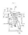
- the pallet stopper 231 a and 231 b are pallet stoppers located at the intermediate sections, rather than the turning sections, of the air table.
- the pallet stopper 231 a (231 b) comprises a retractable stopper plate 235, a guide 237 adapted to support the stopper plate 235, a shock absorber 236 disposed between the stopper plate 235 and the guide 237, a support table 238 on which the guide 237 is supported, a link mechanism 239 by which the support table 238 is vertically movable relative to the base 224, and a drive cylinder 240 mounted between the link mechanism 239 and the base 224.
- the pallet stopper 231 a is located at the intermediate sections, rather than the 90 turning sections, of the air table 224.
- the pallet 227 is first placed on the air table 221, and a load is mounted on the pallet 227.
- the ball of the ball valve 222 is pushed down against the action of the spring. Air under pressure is applied to the pallet 227 to float the pallet 227 together with the load.
- the acceleration primary coils 223a are operable to accelerate the pallet 227.
- the pallet 227 is moved in the direction of the arrow X shown in Fig. 14.
- the guide rollers 228 are rotated within the grooved guide 225 to guide the pallet 227 toward the station A, for example.
- the drive cylinder 240 is operable to lift the support table 238, the guides 237 and the shock absorber 236 and the stopper plate 235 through the link mechanism 239. This causes the stopper plate 235 to contact the pallet 227.
- the resulting shock is absorbed by the shock absorber 236 so that the pallet 227 may be stopped in the intermediate section of the air table without any shocks.
- the drive cylinder 240 of the pallet stopper 231 b is rendered operative to lift up the support table 238, the guides 237, the shock absorber 236 and the stopper plate 235 through the link mechanism 239. This causes the stopper plate 235 to position in the rear of the pallet 227.
- the drive cylinders 240 of the pallet stoppers 231 a and 231 are rendered operative to lower the stopper plates 235, 235.
- the pallet together with the load is then moved toward the next station or 90 turning section of the air table in a manner as will hereinafter be described.
- the deceleration primary coils 225b are energized to reduce the speed of the pallet 227.
- the pallet 227 is stopped when it contacts with the pallet stopper 230. Thereafter, the pallet 227 together with the load is moved toward the next station.
- the pallets of the first to third embodiments may be used in a press process in which glass products such as a cathod-ray tube or funnel are made, or in a transfer process of pressed products. Also, the pallets may be used to transfer other loads in a press or transfer process. It is not essential that the shape of the pallet be square.
- the pallet may be rectangular, hexagonal or polygonal. The direction of conveyance of the pallet may be changed by 120 when a hexagonal pallet is employed.
- each turning section of the air table may be in the form of T or cross or may have a plurality of branches. In the latter case, it is preferable that a retractable stopper is provided at each turning section.
- 301 is a transfer pallet.
- 302 is a pallet body.
- the pallet body 302 has a rigid lower surface.
- the pallet body 302 is light and is made, for example, of aluminum.
- 303 is an external load.
- the external load part 303 has an upper circular loading section 303a and a lower contact section.
- the external load part 303 is made of metal such as iron so that it may not be deformed or broken.
- the circular loading section 303a of the external load part 303 is received in a circular recess centrally formed in the pallet body 302.
- the contact section 303b of the external load part 303 is fit in a recess formed in the lower surface of the pallet body 302.
- the external load part 303 is thus integral with the pallet body 302. 304 are bolts by which the external load part 303 (contact section 303b) is secured to the pallet body 302. As shown in Fig. 21, the external load part 303 (contact section 303b) projects downwardly from the lower surface of the pallet body 302 by about 1 mm.
- 306 is an air table.
- 305 is a clearance left between the pallet body 302 and the air table 306 when the pallet 301 is placed on the air table 306.
- 307 are guide rollers mounted on each corner of the pallet body 302.
- 308 are a number of ball valves formed in the entire air table 306.
- 309 is a bevel portion formed in the lower corner of the pallet 301 for contact with each ball of the ball valve 308 (When the ball is brought into contact with the pallet body 302, it is pushed down to open each air inlet).
- 310 is a secondary linear motor conductor received in a recess formed in the lower surface of the pallet body 302.
- the secondary conductor 310 is an iron plate welded to the lower surface of the pallet body 302 and has a lower end which does not project from the lower surface of the pallet body 302.
- 311 is a grooved guide mounted to the air table 306 to receive the guide rollers 307.
- 312 is a mounting plate by which the grooved guide 311 is mounted to the air table 306. As shown in Figs. 20 and 24, it is sufficient to attach the mounting plate 312 to only one side of the air table 306 to guide the pallet.
- 314a are acceleration primary coils of a linear motor mounted to the air table 306.
- 314b are deceleration primary coils mounted to the air table 306.
- the ball valve 308 and the associated ball are the same as those used in the first to third embodiments.
- the air table is a rectangular frame as in the first to third embodiments.
- the acceleration primary coils 314a and the deceleration primary coils 314b are arranged in the same manner as those in the third embodiment.
- the longitudinal central axis of one station extends at right angles to that of another station.
- Operation of the transfer pallet in the fourth embodiment shown in Figs. 20 to 24 is as follows.
- the pallet 301 is placed in the air table 306, and a load is also placed on the external load part 303 (circular loading station 303a). Air under pressure is then applied through the ball valves 308 to float the pallet 301 together with the load above the air table 306.
- the acceleration primary coils 314a are energized to accelrate the pallet 301.
- the guide rollers 307 of the pallet 301 and the grooved guide 311 cooperate to guide the pallet 301. This prevents irregular movement of the pallet 301 until the pallet 301 reaches a station.
- the ball valves 308 are sequentially rendered ON (opened) by the rigid lower surface of the pallet 301 to keep the pallet 301 lifted above the air table.
- the balls 308 are pushed up by air under pressure and by the spring so as to render the ball valves OFF (or to close the ball valves).
- the deceleration primary coils are operable to reduce the speed of the pallet 301.
- the pallet 301 is thereafter stopped by stoppers.
- These stoppers may include the pallet stoppers 28 to 30 of the first embodiment, the pallets stoppers 133 of the second embodiment, and the pallet stoppers 230, 231 a, and 231 b of the third embodiment.
- the ball valve 308, located immediately below the pallet 301 is closed by means not shown.
- the external load part 303 made of iron (contact section 303b) is placed on the air table 306. Since the lower surface of the external load part (contact section 303b) projects slightly from the lower surface of the pallet body 302, the pallet body 302 made of a light material is in no way contacted with the air table 306.
- the external load part (contact section 303b) is in contact with the air table 306.
- Figs. 25 and 26 illustrate a fifth embodiment of the present invention wherein a secondary conductor 310 includes an aluminum plate 316 and a steel plate 317 attached to the aluminum plate 316 and is fit in the recess formed in the lower surface of the pallet body as in the fourth embodiment.
- a portion of the aluminum plate 316 which is not engaged with the ball valves 308 is recessed as at 318a to provide an air pocket 318. Air under pressure is applied from the ball valves 308 to the air pocket 318 to more positively float the pallet 301.
- the operation of the rest of the fifth embodiment is identical to that of the embodiment shown in Figs. 20 to 24.
- the pallets of the fourth and fifth embodiments may be used in a press process in which glass products such as a cathod-ray tube or funnel are made, or in a transfer process of pressed products. Also, the pallets may be used to transfer other loads in a press or transfer process. It is not essential that the shape of the pallets be square.
- the pallets may be rectangular, hexagonal or polygonal. The direction of convetance of the pallet may be changed by 120 when a hexagonal pallet is employed.
- each turning section of the air table may be in the form of T or cross or may have a plurality of branches. In the latter case, it is preferable that a retractable stopper is provided at each turning section.
- the pallet is placed on the air table, and a load is placed on the pallet.
- the ball valve located immediately below the pallet, is opened to apply air under pressure to float the pallet.
- the primary coil of the linear motor is then energized to accelerate the pallet.
- the pallet is moved toward a station while the guide of the pallet is engaged with the guides of the air table.
- the primary coil of the linear motor is energized to reduced the speed of the pallet, and the pallet stoppers are operable to stop the pallet.
- the pallet is thereafter moved to a next station.
- the pallet together with the load can be moved exactly on and along the air table.
- This arrangement eliminates the need for a turning section of an increased radius of curvature. Also, the overall transfer system can be well organized or arranged.
- the deceleration primary coil of the linear motor is energized to reduce the speed of the pallet.
- the pallet is stopped when it comes into contact with the pallet stoppers. At this time, the guide roller at the inner front of the pallet is moved into the grooved guide through the recess.
- the acceleration primary coil of the linear motor is energized to accelerate the pallet.
- the pallet is moved to the turning section of the air table.
- the guide roller at the inner rear of the pallet is moved out of the grooved guide through the recess.
- the direction of conveyance of the pallet is changed in a similar manner.
- the pallet can smoothly be transferred.
- the pallet can smoothly be stopped in each turning station. Also, the direction of conveyance of the pallet can smoothly be changed.
- the pallet is placed on the air table, and a load is placed on the pallet. Air under pressure is applied from the ball valves to the pallet.
- the acceleration primary coil of the linear motor is energized to accelerate the floating pallet.
- the pallet is moved to the intermediate section while the guide of the pallet is engaged with the guides of the air table.
- the deceleration primary coil of the linear motor is energized to reduce the speed of the pallet.
- the pallet is stopped when it comes into contact with the pallet stoppers. After the load has been processed, the pallet is moved in a similar manner to the next station while being guided by the guides.
- the pallet stopper mounted to the outer turning section in a face-to-face relation to the pallet as conveyed is operable to stop the pallet.
- the pallet is then moved in an intended different direction.
- This arrangement eliminates the need for a turning section of an increased radius of curvature and enables neet arrangement of the overall transfer system. Also, the pallet together with a load can accurately be stopped in a predetermined position. This improves the operability as well as safety in a production line.
- the transfer pallet comprises a pallet body made from a light material, and an external load part made of metal. This results in a decrease in the weight of the overall pallet and enable a corresponding reduction in the size of the linear motor and the flow of air under pressure, and thus, the size of the transfer system wherein the air table and the linear motor cooperate to float and tranfer the pallet.
- the lower surface of the external load part projects slightly downwardly from the lower surface of the pallet body. This allows the external load part to accommodate any external forces. Thus, no external force is exerted on the pallet body.
- the pallet can thus has a required strength.
Landscapes
- Engineering & Computer Science (AREA)
- Mechanical Engineering (AREA)
- Physics & Mathematics (AREA)
- Fluid Mechanics (AREA)
- Non-Mechanical Conveyors (AREA)
- Special Conveying (AREA)
- Control Of Conveyors (AREA)
Abstract
Description
- The present invention relates to a transfer system for transferring a load such as a heavy object to be processed, and a transfer pallet on which the load is placed.
- Figs. 27 to 31 show transfer systems known in the art.
- Referring first to Figs. 27 to 29, a conventional transfer system includes a
truck 1. 2 is a table connected to atruck body 3 by avertical support 2'. 6 are wheels rotatable about a horizontal shaft which is mounted to thetruck body 3. 4 is a guide of a U-shaped cross section. 5 are a pair of rails fixed to the inner walls of theguide 4. Thewheels 6 of thetruck 1 are supported on therails 5. 7 are wheels each rotatable about a vertical shaft which is connected to thetruck body 3. Thewheels 7 are in contact with the inner side walls of theguide 4. 8 is a secondary conductor of a linear motor. 9 are primary coils of the linear motor which are fixedly mounted on the bottom of theguide 4 and spaced apart from one another in the direction in which the truck is advanced. 10 are stations. 11 is a turning section of theguide 4 constructed to change the direction of advancement of the truck. With this arrangement, thewheels 6 are placed on therails 5, and thewheels 7 are brought into contact with the side walls of theguide 4. A load (a heavy object to be processed) is placed on the table 2. Thetruck 1 is moved from onestation 10 to anotherstation 10 along theguide 4 when the linear motorprimary coils 9 are energized. - Figs 30 and 31 show another transfer system known in the art. 14 is a base. 15 is an air duct seated on the
base 14. 12 is a top plate of theair duct 15. 13 are a number of nozzle holes formed in the entire surface of thetop plate 12. 16 are linear motor primary coils mounted within theair duct 15. 17 is a pallet including a linear motor secondary conductor on its lower surface. 18 is a pressurized air supply source. Thebase 14 and the air duct together form an air table. Air under pressure is supplied from the pressurized air supply source to theair duct 15 and then injected from thenozzles 13 to float thepallet 17 together with a load above thetop plate 12 of theair duct 15. Thepallet 17 together with the load is transferred from one station to another station when the linear motorprimary coils 16 are energized. - Conventionally, a transfer system employs a pallet to carry a light load of several kilograms to several hundred kilograms. The pallet together with the light load is floated on an air table and moved by a linear motor as shown, for example, in Figs. 30 and 31.
- In the prior art transfer system shown in Figs. 27 to 29, the table 2 is attached to the
truck 1 by a single post or support 2'. This causes the table 2 to swing and move out of alignment with theguide 4. Thus, a load on the table can not be moved in parallel to theguide 4. - Also, if the section 11 of the
guide 4 has a small radius of curvature, a pair offront wheels 6, the fourwheels 7 and a pair of rear wheels are oriented as shown in Fig. 28. This inhibits a change in the direction of movement of thetruck 1. To this end, theguide 4 is constructed in a factory so that the section 11 may have a large radius of curvature. This deteriorates systematic arrangement of the transfer system. In addition, thetruck 1 can not be stopped in a predetermined position. This deteriorates the operability and safety in a production line. - In the prior art transfer system shown in Figs. 30 and 31, a large pressurized air supply source is required to inject air under pressure from a number of
nozzle holes 13 of the air duct (or air table) not only before eachpallet 17 passes, but also after the pallet has passed. This results in an increase not only in the cost of the system, but also consumption of the pressurized air and thus, running cost of the system. - In the prior art transfer system incorporating the air table and the linear motor, a pallet must be rigid and heavy to transfer a heavy load, for example, of several tons (about two tons) at a high speed (2 m/sec). To transfer such a heavy pallet at a high speed, it is necessary to increase size of the linear motor and the flow rate of pressurized air. However, this results in an increase in the overall size of the transfer system.
- In order to improve production efficiency, a pallet is transferred to a press machine in a production or press line while being floated by air under pressure. A force is then applied to press a load on the pallet. The pallet must be rigid to accommodate this force. This results in an increase in the weight of the pallet. To transfer such a heavy pallet, it is necessary to provide a larger linear motor and increase the flow rate of air under pressure. This results in a corresponding increase in the overall size of the press system.
- In view of the foregoing, it is an object of the present invention to provide a transfer system which enables accurate movement of a pallet with a load on an air table, which can systematically be arranged, and which reduces its equipment and running costs.
- Another object of the present invention is to provide a pallet which is lightweight and which can reduce the size of a linear motor and the flow rate of air under pressure and thus, the overall size of a transfer system designed to float the pallet above an air table and move the pallet by the linear motor.
- (1) According to the present invention, there is provided a transfer system comprising an air table, ball valves assembled in the air table, the ball valves, when contacted with a pallet, being opened to apply air under pressure to float the pallet, a linear motor mounted to the air table and adapted to move the floating pallet, and a guide mounted to the air table and adapted to guide the floating pallet.
- (2) According to the present invention, in a transfer system wherein an air table and a linear motor cooperate to float and move a pallet and a load placed on the pallet, the transfer system including a device for changing the direction of conveyance of the pallet comprises acceleration primary coils and deceleration primary coils of the linear motor mounted to turning sections of the air table, pallet stoppers mounted to outer turning sections in a face-to-face relation to the pallet as conveyed, and guides mounted to the turning sections to guide the pallet and including recesses through which guide rollers of the pallet pass.
- (3) According to the present invention, there is provided a transfer system comprising an air table, and a linear motor cooperating with the air table to float and move a pallet and a load placed on the pallet, the transfer system including a guide attached on the outer periphery of the pallet, guides mounted to the air table and adapted for engagement with the guide, pallet stoppers mounted to outer turning sections of the air table in a face-to-face relation to the pallet as conveyed, and retractable pallet stoppers mounted to intermediate sections, rather than the turning sections, of the air table.
- (4) According to the present invention, there is provided a transfer pallet floatable by air under pressure and movable by a linear motor, comprising a pallet body made from a light material, and an external load part made of metal, the external load part having a lower surface projecting slightly from the lower surface of the pallet body, and the pallet body including a plurality of guides on its outer periphery and a secondary conductor of the linear motor on its lower surface.
- In the transfer system (1) of the present in- vetion, the pallet is placed on the air table, and a load is placed on the pallet. The ball valve, located immediately below the pallet, is opened to apply air under pressure to the pallet. The primary coils are then energized to accelerate the floating pallet. The pallet is moved to a station while being guided by the guide. When the pallet reaches the station, the primary coils are energized to reduce the speed of the pallet, and the pallet stoppers are operable to stop the pallet. The pallet is thereafter moved to a next station after the work on this station is completed.
- In the device (2) for changing the direction of conveyance of a pallet, the pallet is placed on the air table, and a load is placed on the pallet. Air under pressure is applied from the ball valves to the pallet. The acceleration primary coils are then energized to accelerate the floating pallet. The guide rollers and the grooved guide cooperate to guide the pallet. When the pallet reaches the turning section of the air table, the deceleration primary coils are energized to reduce the speed of the pallet. The pallet stoppers are then operable to stop the pallet. The guide roller mounted to the inner front of the pallet is moved into the grooved guide through a recess. Thereafter, the acceleration primary coils mounted to the turning section of the air table are energized to accelerate the pallet. At this time, the guide roller mounted to the inner rear of the pallet is moved out of the grooved guide through a recess. When the pallet reaches a next station, the direction of conveyance of the pallet is changed in a similar manner.
- In the transfer system (3) of the present invention, the pallet is placed on the air table, and a load is also placed on the pallet. Air under pressure is applied from the ball valves to the pallet. The acceleration primary coils are then energized to accelerate the floating pallet. The pallet is then moved to a certain station while the guide of the pallet is guided by the guides of the air table. When the pallet reaches the station, the deceleration primary coils are energized to reduce the speed of the pallet. The pallet stoppers are then operable to stop the pallet. After the load has been processed, the pallet is moved to the next or turning section of the air table in the foregoing manner. The pallet is again brought into contact with the pallet stopper and then stopped.
- In the transfer pallet (4) of the present invention, the pallet is placed on the air table, and a load is also placed on the external load part of the paleet. The pallet together with the load is then lifted by air under pressure. The linear motor and the guides cooperate to move the pallet to a predetermined station. When the pallet reaches the station, application of the air under pressure is prevented. This causes the pallet to be placed on the air table. The lower surface of the external load part projects slightly from the lower surface of the pallet body. Thus, the pallet body made from a light material is in no way contacted with the air table. Instead, the external load part made of iron or other metals is brought into contact with the air table to support the load. As a result, no external force (for example, pressing force) is applied to the pallet body.
- For a better understanding of the present invention, reference may be made to the following description of preferred embodiments when taken in conjunction with the accompanying drawings, in which:
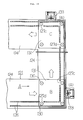
- Fig. 1 is a plan view of a transfer system according to a first embodiment of the present invention;
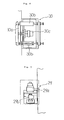
- Fig. 2 is a sectional view of a ball valve;
- Fig. 3 is a sectional view showing the manner in which the ball valves are assembled in the transfer system;
- Fig. 4 is a front view, in vertical section, of a guide;
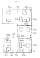
- Fig. 5 is a plan view of pallet stoppers;
- Fig. 6 is a side view of the pallet stoppers;
- Fig. 7 is a side view of the pallet stopper arrag- ned in the intermediate section of an air table;
- Fig. 8 is a plan view of the pallet stopper arranged in the 90 turning corner or section of the air table;
- Fig. 9 is a plan view of the pallet stopper arranged in the intermediate section of the air table;
- Fig. 10 is a plan view of a grooved guide according to a second embodiment of the present invention;
- Fig. 11 is a plan view showing acceleration primary coils and deceleration primary coils of a linear motor;
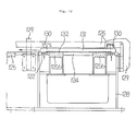
- Fig. 12 is a side view, in vertical section, of an air table employed in the second embodiment;
- Fig. 13 is an enlarged view, in vertical section, of the air table;
- Fig. 14 is a plan view of a transfer system according to a third embodiment of the present invention;
- Fig. 15 is a plan view of a pallet stopper mounted to the 90 turning section;
- Fig. 16 is a side view of the pallet stopper shown in Fig. 15;
- Fig. 17 is a side view of a pallet stopper arranged in the intermediate section;
- Fig. 18 is a side view of a portion of the air table to which the pallet stopper is mounted;
- Fig. 19 is a front view, in vertical section, of the air table;
- Fig. 20 is a plan view showing a fourth embodiment of the present invention;
- Fig. 21 is a side view of the fourth embodiment;
- Fig. 22 is a bottom plan view as seen in the direction of the arrow I in Fig. 21;
- Fig. 23 illustrates a transfer pallet according to the fourth embodiment of the present invention;
- Fig. 23(1) is a side view as seen in the direction of the arrow II in Fig. 20, and Fig. 23(11) is an enlarged side view showing a bevel portion of the pallet body;
- Fig. 24 is a plan view of a transfer system including an air table on which the transfer pallet is moved, and a linear motor by which the transfer pallet is lifted above the air table;
- Fig. 25 is a bottom plan view illustrating a fifth embodiment;
- Fig. 26 is a sectional view taken on the line III-III of Fig. 25;
- Fig. 27 is a front view, in vertical section, of a conventional transfer system;
- Fig. 28 is a plan view showing a turning section in which the direction of conveyance of a pallet is changed;
- Fig. 29 is a plan view showing the layout of the transfer system shown in Fig, 27; and
- Fig. 30 is a plan view of another transfer system known in the art; and
- Fig. 31 is a side view of a conventional transfer system.
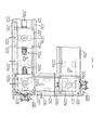
- Figs. 1 to 9 illustrate a first embodiment of the present invention. Referring to Fig. 1 to 6, 26 is an air table or frame of a rectangular shape as viewed in plan. 22 are a number of
ball valves 22 formed in the entire air table 26. Referring to Figs. 2 and 3, 23 is a ball in eachball valve 22. 22a is a spring disposed to urge theball 23 toward avalve seat 22b to close the ball valve. In Figs. 1, 3, 4 and 5, 32 is a pallet. Referring to Fig. 4, 24 are linear motor secondary conductors attached to the lower surface of thepallet 32. 25 is a base of the air table 26. In Figs. 1 and 4, a denotes outer turning section of the air table 26 in a face-to-face relation to the pallet as conveyed. 27 are linear motor primary coils mounted to the air table 26. In Figs. 4 and 5, 35 is a grooved guide provided on the outer periphery of the air table 26. 36 is a mounting plate adapted to fix thegrooved guide 35 to thebase 25. Aguide roller 33 is mounted to each corner of thepallet 32 and rotated within thegrooved guide 35. In Figs. 1, 4, 6 and 9, 30 are pallet stoppers each provided at the front side of the 90 turning section of the air table 26 in the direction of conveyance of the pallet. Eachpallet stopper 30 comprises astopper plate 30a, guides 30b adapted to support retractable guide rods integral with thestopper plate 30a, and ashock absorber 30c disposed between theguides 30b and thestopper plate 30a. Thepallet stoppers 30 are mounted to thebase 25. In Figs. 1 and 5 to 7, 28 are pallet stoppers centrally located in the air table 26. Eachpallet stopper 28 comprises aretractable stopper plate 28a, guides 28a' adapted to support thestopper plate 28a, and ashock absorber 28b disposed between thestopper plate 28a and theguides 28a', a support table 28e adapted to support theguides 28a', alink mechanism 28c adapted to vertically move the support table 28e, and a drive cylinder 28d connected between thelink mechanism 28c and thebase 25. In Figs. 1, 5, 6 and 9, 29 are pallet stoppers cooperating with thepallet stoppers pallet 32 in the 90 turning section and the intermediate section of the air table 26. Eachpallet stopper 29 comprises anair motor 29a, and a wedge-shapedstopper arm 29b. When thepallet 32 comes into contact with thepallet stoppers air motor 29a is energized to swing the wedge-shapedstopper arm 29b in the direction of the arrow shown in Fig. 9. This causes the wedge-shaped stopper plate to come into contact with the rear surface of thepallet 32 and cooperate with thepallet stoppers - As shown in Figs. 1 and 5, the air table has
stations 31 provided at the four turning sections as indicated by C, D, G and H, and the intermediate sections as indicated by A, B, E and F. Thepallet stoppers pallet stoppers - A high pressure air is fed to each
ball valve 22 from its bottom by a source of air supply (not shown). As shown in Fig. 3, theball 22, when the ball valve is closed, is brought into contact with the bottom of thepallet 32 against the action of thespring 22a and air. Air under pressure is introduced into the interior of each ball valve as shown by the arrow in Fig. 3 to cause theball 22 to close the valve. A mechanism may be incorporated to prevent theball 22 from moving down within the valve. This eliminates the need for thesprings 22a. - Each pair of linear motor primary coils are mounted on the air table 26 and located at opposite sides of each of the stations A to H in the direction in which the pallet is conveyed.
- As shown in Fig. 5, a pair of
notches grooved guide 35 to allow theguide rollers 33 to pass. - Operation of the transfer system according to the first embodiment shown in Figs. 1 to 9 is as follows. The
pallet 32 is placed on, for example, the station H. A load is then loaded on thepallet 32. Thepallet 32 is pushed down against the action of thespring 22a. Air under pressure is supplied to float thepallet 32 together with the load. The linear motor primary coils 27 are energized to move the pallet toward the station A while theguide rollers 33 of thepallet 32 is rotated within thegrooved guide 35 of the air table 26. - When the
pallet 32 together with the load has reached the station A of the air table 26, the speed of thepallet 32 is decreased by the linear motor primary coils 27. Thepallet 32 is then brought into contact with thepallet stopper 28 and pushed toward thepallet 28 by thepallet stopper 29. After thepallet 32 is stopped, thepallet stoppers pallet 32 together with the load is then moved toward the station B. Thepallet 32 is stopped in a similar manner. Thepallet 32 is next moved toward the station C or 90 turning section of the air table until it comes into contact with the pallet stopper 90. Thepallet stopper 29 is then operable to push thepallet 32 from its back. This results in stoppage of thepallet 32. Thepallet 32 is repeatedly moved and stopped in a similar manner when it passes the stations D to H. - When the
pallet 32 passes the stations or turning sections of the air table H, C, D and G, theguide rollers 33 are moved through thenotches pallet 32 to change its direction. - A transfer system according to a second embodiment of the present invention will now be described with reference to Figs. 10 to 13. In Figs. 10 to 13, 21 is a transfer system. In Figs. 12 and 13, 124 is a rectangular air frame or table. 122 are pressurized air ball valves assembled in the air table 124. 123 is a ball located within each
ball valve 122. 123a is a spring seat mounted within eachball valve 122. 123b is a spring disposed between thespring seat 123a and theball 123 and adapted to normally urge theball 123 against aspring seat 122a so as to close theball valve 122. Air under pressure is introduced into the interior of theball valve 122 to push theball 123 against thevalve seat 122a. A mechanism may be incorporated to prevent theball 123 from falling down from thevalve seat 122a. This eliminates the need for thespring 123b. - 128 is a base on which the air table 124 is mounted. In Figs. 10 and 11, a denotes a 90 turning section provided at each corner of the air table 124. Fig. 11, 125a are acceleration linear motor primary coils. 125b are deceleration linear motor primary coils of the type known in the art. Each pair of acceleration
primary coils 125 are mounted to the air table 124 in a spaced relation. Each pair of decelerationprimary coils 125b are mounted to the turning section of the air table 124 in a spaced relation. In each turning section, the longitudinal axis of each accelerationprimary coil 125a extends at right angles to the longitudinal axis of each decelerationprimary coil 125b. - In Figs. 10 and 12, 126 is a grooved guide provided on the outer peripheral edge of the air table 124. 129 is a mounting plate by which the
grooved guide 126 is secured to thebase 128. 131 is a transfer pallet. 132 is a linear motor secondary conductor mounted to the lower surface of thepallet 131. 130 are four guide rollers mounted on each corner of thepallet 131 and adapted to rotate within thegrooved guide 126. - 127 and 127d are notches formed in the
grooved guide 126 to pass the guide rollers. These notches are formed in the inner turning section of the air table. - In Fig. 10, 133 are pallet stoppers which are similar in structure to the
pallet stoppers 30 in the first embodiment. Thepallet stoppers 133 are mounted to thegrooved guide 126. - In operation, the
pallet 131 is placed on the air table 124, and a load is loaded on thepallet 131. Theball 123 of theball valve 122 is then pushed down against the action of the spring 134. Air under pressure is applied to thepallet 131. This causes thepallet 131 together with the load to float. - The linear motor
primary coils 125a are operable to move thepallet 131 in the direction of the arrow A shown in Fig. 10. At this time, theguide rollers 130 are rotated within thegrooved guide 126 so as to guide the pallet in that direction. When thepallet 131 reaches the turning section of the air table 124, the decelerationprimary coils 125b are operable to reduce the speed of thepallet 131. Thepallet 131 is stopped when it comes into contact with thepallet stopper 133. At this time, the guide roller, located at the inner front of thepallet 131, is moved into thegrooved guide 126 through thenotch 127c. - The acceleration
primary coils 125a are then operable to accelerate thepallet 131. Thepallet 131 is moved toward the next turning section of the air table 124. At this time, the guide roller, located at the inner rear of thepallet 131, is moved out of thegrooved guide 126 through the notch 27d. When thepallet 131 reaches the next turning section, the pallet is turned by 90 in a similar manner. - A tranfer system according to a third embodiment of the present invention will now be described with reference to Figs. 14 to 19. 221 is a rectangular frame or air table. 222 are pressurized air ball valves assembled in the air table 221. In Figs. 16, 18 and 19, 224 is a base on which the air table 221 is mounted. In Fig. 13, a denotes an outer turning section located at each corner of the
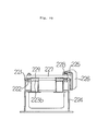
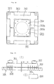
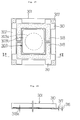
air tbale 221 in a face-to-face relation to the pallet as conveyed and identical in structure to those employed in the first and second embodiments. In Fig. 14, 223a are acceleration linear motor primary coils. 223b are deceleration linear motor primary coils. Each pair of accelerationprimary coils 223a are mounted to the air table 221 in a spaced relation to one another. A pair of decelerationprimary coils 125b are mounted to each 90 turning section of the air table 124 in a spaced relation to one another. In each turning section, the longitudinal axis of each accelerationprimary coil 223a extends at right angles to the longitudinal axis of each decelerationprimary coil 223b. In Figs. 18 and 19, 225 is a grooved guide provided above the outer peripheral edge of the air table 221. 226 is a mounting plate by which thegrooved guide 225 is secured to thebase 224. 227 is a transfer pallet. 229 is a linear motor secondary conductor mounted to the lower surface of thepallet 227. 228 are four guide rollers mounted on each corner of thepallet 227 and adapted to rotate within thegrooved guide 225. - In Figs. 14 to 16 and 18, 230 are pallet stoppers. As shown in Figs. 15 and 16, each
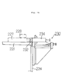
pallet stopper 230 comprises astopper plate 232, a pair ofguides 234 adapted to support a corresponding pair of retractable guide rods integral with thestopper plate 232, and ashock absorber 233 disposed between theguides 234 and thestopper plate 232. Eachpallet stopper 230 is attached to the outer turning section a of the air table 24. - 231 a and 231 b are pallet stoppers located at the intermediate sections, rather than the turning sections, of the air table. As shown in Fig. 17, the
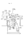
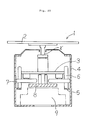
pallet stopper 231 a (231 b) comprises aretractable stopper plate 235, a guide 237 adapted to support thestopper plate 235, ashock absorber 236 disposed between thestopper plate 235 and the guide 237, a support table 238 on which the guide 237 is supported, alink mechanism 239 by which the support table 238 is vertically movable relative to thebase 224, and adrive cylinder 240 mounted between thelink mechanism 239 and thebase 224. Thepallet stopper 231 a is located at the intermediate sections, rather than the 90 turning sections, of the air table 224. - Operation of the transfer system according to the third embodiment of the present invention will now be described with reference to Figs. 14 and 19. The
pallet 227 is first placed on the air table 221, and a load is mounted on thepallet 227. The ball of theball valve 222 is pushed down against the action of the spring. Air under pressure is applied to thepallet 227 to float thepallet 227 together with the load. - The acceleration
primary coils 223a are operable to accelerate thepallet 227. Thepallet 227 is moved in the direction of the arrow X shown in Fig. 14. At this time, theguide rollers 228 are rotated within thegrooved guide 225 to guide thepallet 227 toward the station A, for example. Immediately before thepallet 227 reaches the intermediate section of the air table, thedrive cylinder 240 is operable to lift the support table 238, the guides 237 and theshock absorber 236 and thestopper plate 235 through thelink mechanism 239. This causes thestopper plate 235 to contact thepallet 227. The resulting shock is absorbed by theshock absorber 236 so that thepallet 227 may be stopped in the intermediate section of the air table without any shocks. - After the
pallet 227 is stopped, thedrive cylinder 240 of thepallet stopper 231 b is rendered operative to lift up the support table 238, the guides 237, theshock absorber 236 and thestopper plate 235 through thelink mechanism 239. This causes thestopper plate 235 to position in the rear of thepallet 227. - When processing of the load in the intermediate section is completed, the
drive cylinders 240 of thepallet stoppers 231 a and 231 are rendered operative to lower thestopper plates - When the
pallet 227 together with the load reaches the 90 turning section of the air table 221, the deceleration primary coils 225b are energized to reduce the speed of thepallet 227. Thepallet 227 is stopped when it contacts with thepallet stopper 230. Thereafter, thepallet 227 together with the load is moved toward the next station. - The pallets of the first to third embodiments may be used in a press process in which glass products such as a cathod-ray tube or funnel are made, or in a transfer process of pressed products. Also, the pallets may be used to transfer other loads in a press or transfer process. It is not essential that the shape of the pallet be square. The pallet may be rectangular, hexagonal or polygonal. The direction of conveyance of the pallet may be changed by 120 when a hexagonal pallet is employed.
- In the first to third embodiments thus described, the direction of conveyance of the pallet is changed by 90 but may be changed by any degrees. Each turning section of the air table may be in the form of T or cross or may have a plurality of branches. In the latter case, it is preferable that a retractable stopper is provided at each turning section.
- A transfer pallet according to a fourth embodiment of the present invention will now be described with reference to Figs. 20 to 24. 301 is a transfer pallet. 302 is a pallet body. The
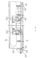
pallet body 302 has a rigid lower surface. Thepallet body 302 is light and is made, for example, of aluminum. 303 is an external load. Theexternal load part 303 has an uppercircular loading section 303a and a lower contact section. Theexternal load part 303 is made of metal such as iron so that it may not be deformed or broken. Thecircular loading section 303a of theexternal load part 303 is received in a circular recess centrally formed in thepallet body 302. Thecontact section 303b of theexternal load part 303 is fit in a recess formed in the lower surface of thepallet body 302. Theexternal load part 303 is thus integral with thepallet body 302. 304 are bolts by which the external load part 303 (contact section 303b) is secured to thepallet body 302. As shown in Fig. 21, the external load part 303 (contact section 303b) projects downwardly from the lower surface of thepallet body 302 by about 1 mm. - 306 is an air table. 305 is a clearance left between the
pallet body 302 and the air table 306 when thepallet 301 is placed on the air table 306. 307 are guide rollers mounted on each corner of thepallet body 302. 308 are a number of ball valves formed in the entire air table 306. 309 is a bevel portion formed in the lower corner of thepallet 301 for contact with each ball of the ball valve 308 (When the ball is brought into contact with thepallet body 302, it is pushed down to open each air inlet). 310 is a secondary linear motor conductor received in a recess formed in the lower surface of thepallet body 302. Thesecondary conductor 310 is an iron plate welded to the lower surface of thepallet body 302 and has a lower end which does not project from the lower surface of thepallet body 302. 311 is a grooved guide mounted to the air table 306 to receive theguide rollers 307. 312 is a mounting plate by which thegrooved guide 311 is mounted to the air table 306. As shown in Figs. 20 and 24, it is sufficient to attach the mountingplate 312 to only one side of the air table 306 to guide the pallet. 314a are acceleration primary coils of a linear motor mounted to the air table 306. 314b are deceleration primary coils mounted to the air table 306. - The
ball valve 308 and the associated ball are the same as those used in the first to third embodiments. The air table is a rectangular frame as in the first to third embodiments. The accelerationprimary coils 314a and the decelerationprimary coils 314b are arranged in the same manner as those in the third embodiment. The longitudinal central axis of one station extends at right angles to that of another station. - Operation of the transfer pallet in the fourth embodiment shown in Figs. 20 to 24 is as follows. The
pallet 301 is placed in the air table 306, and a load is also placed on the external load part 303 (circular loading station 303a). Air under pressure is then applied through theball valves 308 to float thepallet 301 together with the load above the air table 306. The accelerationprimary coils 314a are energized to accelrate thepallet 301. Theguide rollers 307 of thepallet 301 and thegrooved guide 311 cooperate to guide thepallet 301. This prevents irregular movement of thepallet 301 until thepallet 301 reaches a station. - At this time, the
ball valves 308 are sequentially rendered ON (opened) by the rigid lower surface of thepallet 301 to keep thepallet 301 lifted above the air table. When thepallet body 302 is moved away from the air table, theballs 308 are pushed up by air under pressure and by the spring so as to render the ball valves OFF (or to close the ball valves). - When the pallet reaches a certain station, the deceleration primary coils are operable to reduce the speed of the
pallet 301. Thepallet 301 is thereafter stopped by stoppers. These stoppers may include thepallet stoppers 28 to 30 of the first embodiment, thepallets stoppers 133 of the second embodiment, and thepallet stoppers - When the
pallet 301 is thus stopped, theball valve 308, located immediately below thepallet 301, is closed by means not shown. Theexternal load part 303 made of iron (contact section 303b) is placed on the air table 306. Since the lower surface of the external load part (contact section 303b) projects slightly from the lower surface of thepallet body 302, thepallet body 302 made of a light material is in no way contacted with the air table 306. The external load part (contact section 303b) is in contact with the air table 306. By this arrangement, no external force (for example, pressing force) is applied to thepallet body 302. - Figs. 25 and 26 illustrate a fifth embodiment of the present invention wherein a
secondary conductor 310 includes analuminum plate 316 and asteel plate 317 attached to thealuminum plate 316 and is fit in the recess formed in the lower surface of the pallet body as in the fourth embodiment. In the secondary conductor orcomposite material 310, a portion of thealuminum plate 316 which is not engaged with theball valves 308 is recessed as at 318a to provide anair pocket 318. Air under pressure is applied from theball valves 308 to theair pocket 318 to more positively float thepallet 301. The operation of the rest of the fifth embodiment is identical to that of the embodiment shown in Figs. 20 to 24. - The pallets of the fourth and fifth embodiments may be used in a press process in which glass products such as a cathod-ray tube or funnel are made, or in a transfer process of pressed products. Also, the pallets may be used to transfer other loads in a press or transfer process. It is not essential that the shape of the pallets be square. The pallets may be rectangular, hexagonal or polygonal. The direction of convetance of the pallet may be changed by 120 when a hexagonal pallet is employed.
- In the fourth and fifth embodiments thus described, the direction of conveyance of the pallet is changed by 90 but may be changed by any degrees. Each turning section of the air table may be in the form of T or cross or may have a plurality of branches. In the latter case, it is preferable that a retractable stopper is provided at each turning section.
- Advantages of the present invention are as follows.
- In the invention as set forth in
claim 1, the pallet is placed on the air table, and a load is placed on the pallet. The ball valve, located immediately below the pallet, is opened to apply air under pressure to float the pallet. The primary coil of the linear motor is then energized to accelerate the pallet. The pallet is moved toward a station while the guide of the pallet is engaged with the guides of the air table. When the pallet reaches the station, the primary coil of the linear motor is energized to reduced the speed of the pallet, and the pallet stoppers are operable to stop the pallet. The pallet is thereafter moved to a next station. Thus, the pallet together with the load can be moved exactly on and along the air table. - This arrangement eliminates the need for a turning section of an increased radius of curvature. Also, the overall transfer system can be well organized or arranged.
- Only the ball valve which is located immediately below the pallet is opened. This allows the use of a smaller source of pressurized air supply so as to reduce the equipment cost of the system. Also, it enables a reduction in the consumption of air under pressure and thus, the running cost of the transfer system.
- In the invention as set forth in
claim 2, when the pallet together with a load reaches the turning station of the air table, the deceleration primary coil of the linear motor is energized to reduce the speed of the pallet. The pallet is stopped when it comes into contact with the pallet stoppers. At this time, the guide roller at the inner front of the pallet is moved into the grooved guide through the recess. - Next, the acceleration primary coil of the linear motor is energized to accelerate the pallet. The pallet is moved to the turning section of the air table. At this time, the guide roller at the inner rear of the pallet is moved out of the grooved guide through the recess. When the pallet reaches the next turning station, the direction of conveyance of the pallet is changed in a similar manner.
- In the invention of
claim 2 thus explained, the pallet can smoothly be transferred. The pallet can smoothly be stopped in each turning station. Also, the direction of conveyance of the pallet can smoothly be changed. - In the invention as set forth in
claim 3, the pallet is placed on the air table, and a load is placed on the pallet. Air under pressure is applied from the ball valves to the pallet. The acceleration primary coil of the linear motor is energized to accelerate the floating pallet. The pallet is moved to the intermediate section while the guide of the pallet is engaged with the guides of the air table. When the pallet reaches the intermediate section, the deceleration primary coil of the linear motor is energized to reduce the speed of the pallet. The pallet is stopped when it comes into contact with the pallet stoppers. After the load has been processed, the pallet is moved in a similar manner to the next station while being guided by the guides. - In each turning section of the air table, the pallet stopper mounted to the outer turning section in a face-to-face relation to the pallet as conveyed is operable to stop the pallet. The pallet is then moved in an intended different direction. This arrangement eliminates the need for a turning section of an increased radius of curvature and enables neet arrangement of the overall transfer system. Also, the pallet together with a load can accurately be stopped in a predetermined position. This improves the operability as well as safety in a production line.
- In the invention as set forth in
claim 4, the transfer pallet comprises a pallet body made from a light material, and an external load part made of metal. This results in a decrease in the weight of the overall pallet and enable a corresponding reduction in the size of the linear motor and the flow of air under pressure, and thus, the size of the transfer system wherein the air table and the linear motor cooperate to float and tranfer the pallet. - The lower surface of the external load part projects slightly downwardly from the lower surface of the pallet body. This allows the external load part to accommodate any external forces. Thus, no external force is exerted on the pallet body. The pallet can thus has a required strength.
Claims (4)
Applications Claiming Priority (10)
| Application Number | Priority Date | Filing Date | Title |
|---|---|---|---|
| JP20814190 | 1990-08-08 | ||
| JP208140/90 | 1990-08-08 | ||
| JP20813890 | 1990-08-08 | ||
| JP20813990 | 1990-08-08 | ||
| JP20814090 | 1990-08-08 | ||
| JP208138/90 | 1990-08-08 | ||
| JP208141/90 | 1990-08-08 | ||
| JP208139/90 | 1990-08-08 | ||
| JP3175256A JPH04350023A (en) | 1990-08-08 | 1991-07-16 | Conveyor and pallet for conveying |
| JP175256/91 | 1991-07-16 |
Publications (2)
| Publication Number | Publication Date |
|---|---|
| EP0470627A1 true EP0470627A1 (en) | 1992-02-12 |
| EP0470627B1 EP0470627B1 (en) | 1994-12-14 |
Family
ID=27528633
Family Applications (1)
| Application Number | Title | Priority Date | Filing Date |
|---|---|---|---|
| EP91113364A Expired - Lifetime EP0470627B1 (en) | 1990-08-08 | 1991-08-08 | Transfer system |
Country Status (5)
| Country | Link |
|---|---|
| US (1) | US5248236A (en) |
| EP (1) | EP0470627B1 (en) |
| JP (1) | JPH04350023A (en) |
| KR (1) | KR920004259A (en) |
| DE (1) | DE69105863T2 (en) |
Cited By (4)
| Publication number | Priority date | Publication date | Assignee | Title |
|---|---|---|---|---|
| US5447220A (en) * | 1994-04-07 | 1995-09-05 | Weskamp; Robert J. | Method and apparatus for stabilizing pallet-type conveyor systems |
| WO2001021513A1 (en) * | 1999-04-16 | 2001-03-29 | Deutsches Zentrum für Luft- und Raumfahrt e.V. | Fluid cushion transport system |
| EP1254853A2 (en) * | 2001-04-30 | 2002-11-06 | Gämmerler AG | Handling system |
| EP3450090A1 (en) * | 2017-05-18 | 2019-03-06 | Wilhelm Altendorf GmbH & Co. KG | Air-cushion table |
Families Citing this family (16)
| Publication number | Priority date | Publication date | Assignee | Title |
|---|---|---|---|---|
| US7959395B2 (en) | 2002-07-22 | 2011-06-14 | Brooks Automation, Inc. | Substrate processing apparatus |
| US7988398B2 (en) | 2002-07-22 | 2011-08-02 | Brooks Automation, Inc. | Linear substrate transport apparatus |
| US6848566B2 (en) * | 2003-06-30 | 2005-02-01 | The Procter & Gamble Company | Continuously adjustable apparatus for repositioning discrete articles |
| TWI295659B (en) * | 2003-08-29 | 2008-04-11 | Daifuku Kk | Transporting apparatus |
| KR100956348B1 (en) * | 2003-09-05 | 2010-05-06 | 삼성전자주식회사 | Inline transfer system |
| US8602706B2 (en) * | 2009-08-17 | 2013-12-10 | Brooks Automation, Inc. | Substrate processing apparatus |
| JP4804567B2 (en) * | 2009-09-17 | 2011-11-02 | 東京エレクトロン株式会社 | Substrate floating device |
| JP2014010862A (en) * | 2012-06-29 | 2014-01-20 | Fujitsu Ltd | Library device |
| US10858202B1 (en) | 2014-04-14 | 2020-12-08 | Amazon Technologies, Inc. | Air cushioned materials handling system |
| JP6501078B2 (en) * | 2016-04-29 | 2019-04-17 | 株式会社ダイフク | Conveying equipment using traveling vehicle |
| CN107161633A (en) * | 2017-06-28 | 2017-09-15 | 大族激光科技产业集团股份有限公司 | Circulating transmission device |
| JP6803476B2 (en) * | 2017-08-29 | 2020-12-23 | 株式会社Fuji | Work transfer system |
| CN107973073B (en) * | 2017-11-30 | 2019-04-30 | 清华大学 | The sample transfer device of ultrahigh vacuum biography sample system |
| EP3772477A1 (en) * | 2019-08-08 | 2021-02-10 | Renishaw PLC | Pallet loader for a positioning apparatus |
| CN117242352A (en) * | 2021-05-13 | 2023-12-15 | 株式会社日立高新技术 | Sample conveying device, sample analysis system, and sample conveying method |
| CN113511517B (en) * | 2021-05-20 | 2022-05-20 | 哈尔滨工业大学 | Air-flotation transportation transition method |
Citations (5)
| Publication number | Priority date | Publication date | Assignee | Title |
|---|---|---|---|---|
| US3610695A (en) * | 1969-02-19 | 1971-10-05 | Fuji Photo Film Co Ltd | Electromagnetic-induction-type noncontact conveying apparatus |
| GB1297727A (en) * | 1970-07-16 | 1972-11-29 | ||
| US3889602A (en) * | 1974-03-13 | 1975-06-17 | Gerald L Barber | Method and apparatus for transporting |
| DE2717035A1 (en) * | 1977-04-18 | 1978-10-26 | Fraunhofer Ges Forschung | Automatic transport mechanism for separate items - has independently travelling drive units automatically coupling to, and uncoupling from, pallets |
| US4718539A (en) * | 1985-01-02 | 1988-01-12 | Hitachi, Ltd. | Conveyor means |
Family Cites Families (5)
| Publication number | Priority date | Publication date | Assignee | Title |
|---|---|---|---|---|
| JPS5748520A (en) * | 1980-09-03 | 1982-03-19 | Shinko Electric Co Ltd | Stop method for carrier in conveyor |
| US4444541A (en) * | 1981-12-18 | 1984-04-24 | Bergman Raymond A | Air float power translation and rotation system |
| JPS5931208A (en) * | 1982-08-09 | 1984-02-20 | Shinko Electric Co Ltd | Positioning device for object transported on conveyor |
| JPS61169669U (en) * | 1984-12-03 | 1986-10-21 | ||
| JPS62160972A (en) * | 1986-01-07 | 1987-07-16 | Nissan Motor Co Ltd | Heavy article transfer device |
-
1991
- 1991-07-16 JP JP3175256A patent/JPH04350023A/en not_active Withdrawn
- 1991-08-01 US US07/738,908 patent/US5248236A/en not_active Expired - Fee Related
- 1991-08-08 KR KR1019910013696A patent/KR920004259A/en not_active Application Discontinuation
- 1991-08-08 DE DE69105863T patent/DE69105863T2/en not_active Expired - Fee Related
- 1991-08-08 EP EP91113364A patent/EP0470627B1/en not_active Expired - Lifetime
Patent Citations (5)
| Publication number | Priority date | Publication date | Assignee | Title |
|---|---|---|---|---|
| US3610695A (en) * | 1969-02-19 | 1971-10-05 | Fuji Photo Film Co Ltd | Electromagnetic-induction-type noncontact conveying apparatus |
| GB1297727A (en) * | 1970-07-16 | 1972-11-29 | ||
| US3889602A (en) * | 1974-03-13 | 1975-06-17 | Gerald L Barber | Method and apparatus for transporting |
| DE2717035A1 (en) * | 1977-04-18 | 1978-10-26 | Fraunhofer Ges Forschung | Automatic transport mechanism for separate items - has independently travelling drive units automatically coupling to, and uncoupling from, pallets |
| US4718539A (en) * | 1985-01-02 | 1988-01-12 | Hitachi, Ltd. | Conveyor means |
Cited By (5)
| Publication number | Priority date | Publication date | Assignee | Title |
|---|---|---|---|---|
| US5447220A (en) * | 1994-04-07 | 1995-09-05 | Weskamp; Robert J. | Method and apparatus for stabilizing pallet-type conveyor systems |
| WO2001021513A1 (en) * | 1999-04-16 | 2001-03-29 | Deutsches Zentrum für Luft- und Raumfahrt e.V. | Fluid cushion transport system |
| EP1254853A2 (en) * | 2001-04-30 | 2002-11-06 | Gämmerler AG | Handling system |
| EP1254853A3 (en) * | 2001-04-30 | 2004-01-02 | Gämmerler AG | Handling system |
| EP3450090A1 (en) * | 2017-05-18 | 2019-03-06 | Wilhelm Altendorf GmbH & Co. KG | Air-cushion table |
Also Published As
| Publication number | Publication date |
|---|---|
| EP0470627B1 (en) | 1994-12-14 |
| KR920004259A (en) | 1992-03-27 |
| JPH04350023A (en) | 1992-12-04 |
| DE69105863T2 (en) | 1995-06-22 |
| US5248236A (en) | 1993-09-28 |
| DE69105863D1 (en) | 1995-01-26 |
Similar Documents
| Publication | Publication Date | Title |
|---|---|---|
| EP0470627A1 (en) | Transfer system | |
| US6293454B1 (en) | Installation for positioning and welding body parts of different types of motor vehicles | |
| US6234737B1 (en) | Robotic container handler system | |
| US5177862A (en) | Automatic assembly system | |
| CN102470420A (en) | Work transfer device and work transfer unit for press machine | |
| KR101860195B1 (en) | the transfer robot and the transfer system therewith | |
| US6764266B2 (en) | Robotic parts handler system | |
| US5191958A (en) | Automatic framing system | |
| DE2755147A1 (en) | CONVEYOR SYSTEM, IN PARTICULAR DRAG CHAIN CIRCULAR CONVEYORS | |
| DE4322403C1 (en) | Conveyor-band arrangement | |
| KR19990035783A (en) | Metal sheet cutting and / or welding method and apparatus therefor | |
| JPH10180378A (en) | Lift and clamp device of transfer feeder | |
| CN113277300A (en) | Conveying device | |
| US6000327A (en) | Work conveyor of transfer press | |
| CN1070106C (en) | Apparatus and methods for forming workpieces | |
| EP0857152B1 (en) | Method and device for extracting rolling pallets in compact storage technology, and rolling pallet therefor | |
| KR100539078B1 (en) | Apparatus for aligning and transferring panels for pressing system | |
| GB1594565A (en) | Conveyor devices | |
| CN219173503U (en) | Conveying guide correction mechanism for cargo pallet | |
| CN217806738U (en) | Roller bed device capable of realizing flexible transmission | |
| CN216995098U (en) | Box feeding machine | |
| CN217534660U (en) | Automatic feeding device of press machine special for forming carframe longitudinal beam | |
| CN221092485U (en) | Automatic change commodity circulation handling device | |
| CN220906395U (en) | Solid plate clamping transfer machine | |
| CN118145292B (en) | Automatic overturning equipment and overturning operation method |
Legal Events
| Date | Code | Title | Description |
|---|---|---|---|
| PUAI | Public reference made under article 153(3) epc to a published international application that has entered the european phase |
Free format text: ORIGINAL CODE: 0009012 |
|
| 17P | Request for examination filed |
Effective date: 19910905 |
|
| AK | Designated contracting states |
Kind code of ref document: A1 Designated state(s): DE NL |
|
| 17Q | First examination report despatched |
Effective date: 19930413 |
|
| GRAA | (expected) grant |
Free format text: ORIGINAL CODE: 0009210 |
|
| AK | Designated contracting states |
Kind code of ref document: B1 Designated state(s): DE NL |
|
| REF | Corresponds to: |
Ref document number: 69105863 Country of ref document: DE Date of ref document: 19950126 |
|
| PGFP | Annual fee paid to national office [announced via postgrant information from national office to epo] |
Ref country code: DE Payment date: 19950809 Year of fee payment: 5 |
|
| PGFP | Annual fee paid to national office [announced via postgrant information from national office to epo] |
Ref country code: NL Payment date: 19950825 Year of fee payment: 5 |
|
| PLBE | No opposition filed within time limit |
Free format text: ORIGINAL CODE: 0009261 |
|
| STAA | Information on the status of an ep patent application or granted ep patent |
Free format text: STATUS: NO OPPOSITION FILED WITHIN TIME LIMIT |
|
| 26N | No opposition filed | ||
| PG25 | Lapsed in a contracting state [announced via postgrant information from national office to epo] |
Ref country code: NL Effective date: 19970301 |
|
| NLV4 | Nl: lapsed or anulled due to non-payment of the annual fee |
Effective date: 19970301 |
|
| PG25 | Lapsed in a contracting state [announced via postgrant information from national office to epo] |
Ref country code: DE Effective date: 19970501 |