EP0470585A1 - Plastic garment hanger - Google Patents
Plastic garment hanger Download PDFInfo
- Publication number
- EP0470585A1 EP0470585A1 EP91113231A EP91113231A EP0470585A1 EP 0470585 A1 EP0470585 A1 EP 0470585A1 EP 91113231 A EP91113231 A EP 91113231A EP 91113231 A EP91113231 A EP 91113231A EP 0470585 A1 EP0470585 A1 EP 0470585A1
- Authority
- EP
- European Patent Office
- Prior art keywords
- tongue
- hanger
- abutment part
- extension
- resilient
- Prior art date
- Legal status (The legal status is an assumption and is not a legal conclusion. Google has not performed a legal analysis and makes no representation as to the accuracy of the status listed.)
- Granted
Links
Images
Classifications
-
- A—HUMAN NECESSITIES
- A47—FURNITURE; DOMESTIC ARTICLES OR APPLIANCES; COFFEE MILLS; SPICE MILLS; SUCTION CLEANERS IN GENERAL
- A47G—HOUSEHOLD OR TABLE EQUIPMENT
- A47G25/00—Household implements used in connection with wearing apparel; Dress, hat or umbrella holders
- A47G25/14—Clothing hangers, e.g. suit hangers
- A47G25/48—Hangers with clamps or the like, e.g. for trousers or skirts
- A47G25/50—Hooks on hangers for supporting trousers or skirts
-
- A—HUMAN NECESSITIES
- A47—FURNITURE; DOMESTIC ARTICLES OR APPLIANCES; COFFEE MILLS; SPICE MILLS; SUCTION CLEANERS IN GENERAL
- A47G—HOUSEHOLD OR TABLE EQUIPMENT
- A47G25/00—Household implements used in connection with wearing apparel; Dress, hat or umbrella holders
- A47G25/14—Clothing hangers, e.g. suit hangers
- A47G25/28—Hangers characterised by their shape
Definitions
- Clothes or laundry hangers of this type are known from the utility model 89 02 362 of the applicant.
- the resilient tongues can be spread relatively far, for example in order to insert a thicker piece of clothing into the clamps, but there is a risk that if the resilient tongues deflect too strongly, the extensions will also break off in the known brackets formed the temple ends so that they are only slightly resilient.
- the invention is therefore based on the object of providing a clothes or laundry hanger in which, even with unskillful handling and excessive spreading of the resilient tongues, these do not break off and the extensions on the ends of the hanger are highly resilient.
- extension is designed as a rigid part having a web wall and an upper flange and the distance of the upper edge of the stiffening wall of the tongue from the lower end of the extension is such that the tongue with maximum permissible deflection bumps against the extension.
- the resilient leg can be moved into the open position until it abuts the stop formed by the extension.
- the clothes or laundry hanger shown has a double T-shaped cross section and has a vertical web wall 3, an upper flange 4 and a lower flange 5.
- Clamps 6 and 7 are arranged at the temple ends, each of which is composed of a rigid abutment part 8 and a resilient tongue 9 connected to it in one piece.
- the gaps of terminals 6 and 7 are directed downwards and outwards, so that, for example, a bundle of underpants can easily be inserted into terminals 6 and 7.
- the resilient tongue 9 touches the abutment part 8 in the area of a hump.
- the gap between the abutment part 8 and the tongue 9 is widened like a funnel at the entrance for easy insertion of a laundry part to be clamped.
- the resilient tongue 9 is connected to the abutment part 8 via an exposed, arcuate connecting part 10.
- the accumulation of material in the connecting part 10 ensures that when the laundry hanger is removed from the injection mold while it is still hot, the plastic ring 10 on the outer jacket cools down faster than in the inner region and the shrinking process that occurs during further cooling causes the resilient tongue 9 to be biased against the hump of the abutment part 8 is pressed.
- the resilient tongue 9, which rests with pretension, is stiffened by a web wall 11, so that the spring action comes solely from the arcuate connecting part 10.
- projections 12 are molded on above the exposed connecting parts 10, which extend the back or shoulder line of the hanger towards the temple ends and form rounded corners on the temple ends.
- These extensions 12 have the effect that a shirt, a jacket or a corresponding item of clothing or laundry can be arranged more conveniently on the clothes or laundry hanger.
- the extension 12 is designed as a rigid part and has an upper chord and a web wall 3. It forms a stop for the resilient tongue 9. When the clamps 6, 7 are opened, the tongue 9 strikes the edge of the stiffening wall 11 against the lower, outer end of the extension 12.
- the resilient tongues 15 point with their free ends to the hook 2.
- the resilient tongue 15 is aligned with the back or shoulder line of the Bracket.
- small inlet dents 16 are formed in the bracket, which together with the free ends of the tongues 15 form funnel-like extensions of the gaps in the clamps 14.
- loop tongues 17 are arranged on the underside of the bracket.
Abstract
Description
Die Erfindung betrifft einen Kleider- oder Wäschebügel im Spritzverfahren aus Kunststoff, insbesondere Polystyrol, hergestellt, dessen Querschnitt Doppel-T-förmig ist und eine vertikale Stegwand, einen Obergurt und einen Untergurt aufweist und an dessen Bügelenden nach unten und außen gerichtete Klemmen angeordnet sind, die sich aus je einem im wesentlichen starren Widerlagerteil und einer einstückig damit verbundenen federnden Zunge zusammensetzen, wobei
- - der Gurt das Widerlagerteil umrandet und
- - die federnde Zunge aus einem dem Gurt des Widerlagerteils entsprechenden und mit ihm zusammenwirkenden Rand und einer den Rand aussteifenden Wand besteht und über ein bogenförmiges, freiliegendes, in den Gurt des Widerlagerteils und in den Rand der Zunge übergehendes Verbindungsteil mit dem Widerlagerteil verbunden ist und
- - im Abstand oberhalb des Verbindungsteils und der Zunge ein die Schulterlinie des Bügels verlängernder und die äußere Ecke des Bügels bildender Fortsatz angeformt ist.
- - The belt edged the abutment part and
- - The resilient tongue consists of an edge corresponding to the belt of the abutment part and cooperating with it and a wall stiffening the edge and is connected to the abutment part via an arcuate, exposed, transition into the belt of the abutment part and into the edge of the tongue and
- - At the distance above the connecting part and the tongue an extension extending the shoulder line of the bracket and forming the outer corner of the bracket is formed.
Kleider- oder Wäschebügel dieser Art sind bekannt aus dem Gebrauchsmuster 89 02 362 der Anmelderin.Clothes or laundry hangers of this type are known from the utility model 89 02 362 of the applicant.
Bei den bekannten Bügeln können zwar die federnden Zungen relativ weit abgespreizt werden, beispielsweise um ein dickeres Kleidungsstück in die Klemmen einzuführen, daber aber besteht die Gefahr, daß bei zu starkem Auslenken der federnden Zungen diese abbrechen.Auch sind bei den bekannten Bügeln die Fortsätze an den Bügelenden so ausgebildet, daß sie nur geringfügig belastbar sind.In the known brackets, the resilient tongues can be spread relatively far, for example in order to insert a thicker piece of clothing into the clamps, but there is a risk that if the resilient tongues deflect too strongly, the extensions will also break off in the known brackets formed the temple ends so that they are only slightly resilient.
Der Erfindung liegt deshalb die Aufgabe zugrunde, einen Kleider- oder Wäschebügel zu schaffen, bei dem auch bei ungeschickter Handhabung und starkem Abspreizen der federnden Zungen diese nicht abbrechen und die Fortsätze an den Bügelenden stark belastbar sind.The invention is therefore based on the object of providing a clothes or laundry hanger in which, even with unskillful handling and excessive spreading of the resilient tongues, these do not break off and the extensions on the ends of the hanger are highly resilient.
Diese Aufgabe wird erfindungsgemäß dadurch gelöst, daß der Fortsatz als ein steifes, eine Stegwand und einen Obergurt aufweisendes Teil ausgebildet ist und der Abstand der oberen Kante der aussteifenden Wand der Zunge vom unteren Ende des Fortsatzes so bemessen ist, daß die Zunge bei maximal zulässiger Auslenkung gegen den Fortsatz stößt.This object is achieved in that the extension is designed as a rigid part having a web wall and an upper flange and the distance of the upper edge of the stiffening wall of the tongue from the lower end of the extension is such that the tongue with maximum permissible deflection bumps against the extension.
Bei dem erfindungsgemäßen Kleider- oder Wäschebügel kann der federnde Schenkel so weit in Öffnungsstellung bewegt werden, bis er gegen den vom Fortsatz gebildeten Anschlag stößt.In the clothes or laundry hanger according to the invention, the resilient leg can be moved into the open position until it abuts the stop formed by the extension.
Weitere Merkmale der Erfindung ergeben sich aus dem Unteranspruch.Further features of the invention result from the subclaim.
In der folgenden Beschreibung wird unter Bezugnahme auf die Zeichnung eines Ausführungsbeispieles die Erfindung näher erläutert.The invention is explained in more detail in the following description with reference to the drawing of an exemplary embodiment.
Die Zeichnung zeigt in
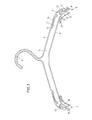
- Fig. 1 eine Ansicht eines Kleider- oder Wäschebügels nach der Erfindung und
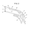
- Fig. 2 eine vergrößerte Ansicht einer Klemme.
- Fig. 1 is a view of a clothes or laundry hanger according to the invention and
- Fig. 2 is an enlarged view of a clamp.
Der dargestellte Kleider- oder Wäschebügel hat einen Doppel-T-förmigen Querschnitt und weist eine vertikale Stegwand 3, einen Obergurt 4 und einen Untergurt 5 auf. An den Bügelenden sind Klemmen 6 und 7 angeordnet, die sich aus je einem starren Widerlagerteil 8 und einer einstückig damit verbundenen federnden Zunge 9 zusammensetzen.The clothes or laundry hanger shown has a double T-shaped cross section and has a
Die Spalte der Klemmen 6 und 7 sind nach unten und außen gerichtet, so daß sich beispielsweise ein Bund einer Unterhose leicht in die Klemmen 6 und 7 einführen läßt. Die federnde Zunge 9 berührt das Widerlagerteil 8 im Bereich eines Hökkers. Der Spalt zwischen dem Widerlagerteil 8 und der Zunge 9 ist zum leichten Einführen eines einzuklemmenden Wäscheteils am Eingang trichterartig erweitert.The gaps of
Die federnde Zunge 9 ist mit dem Widerlagerteil 8 über ein freiliegendes, bogenförmiges Verbindungsteil 10 verbunden. Durch die Materialanhäufung im Verbindungsteil 10 wird erreicht, daß beim noch heißen Entformen des Wäschebügels aus der Spritzform der Kunststoffring 10 am Außenmantel schneller erkaltet als im inneren Bereich und der beim weiteren Erkalten sich einstellende Schrumpfvorgang bewirkt, daß die federnde Zunge 9 mit Vorspannung gegen den Höcker des Widerlagerteiles 8 gedrückt wird.The resilient tongue 9 is connected to the
Die mit Vorspannung anliegende federnde Zunge 9 ist durch eine Stegwand 11 versteift, so daß die Federwirkung allein aus dem bogenförmigen Verbindungsteil 10 kommt.The resilient tongue 9, which rests with pretension, is stiffened by a
Damit der Wäschebügel auch zum Aufhängen von Hemdchen und dergleichen geeignet ist, sind oberhalb der freiliegenden Verbindungsteile 10 Fortsätze 12 angespritzt, welche die Rücken- oder Schulterlinie des Bügels zu den Bügelenden hin verlängern und gerundete Ecken an den Bügelenden bilden. Diese Fortsätze 12 bewirken, daß ein Hemd, eine Jacke oder ein entsprechendes Bekleidungs- oder Wäschestück gefälliger auf dem Kleider- oder Wäschebügel angeordnet werden kann. Der Fortsatz 12 ist als steifes Teil ausgebildet und weist einen Obergurt und eine Stegwand 3 auf. Er bildet einen Anschlag für die federnde Zunge 9. Beim Öffnen der Klemmen 6,7 stößt die Zunge 9 mit der Kante der aussteifenden Wand 11 gegen das untere, äußere Ende des Fortsatzes 12.So that the clothes hanger is also suitable for hanging up shirts and the like,
Auf dem Rücken des Bügels sind in den äußeren Bereichen weitere Klemmen 14 angeordnet, deren federnde Zungen 15 mit ihren freien Enden zum Haken 2 hinweisen. Die federnde Zunge 15 fluchtet mit der Rücken- oder Schulterlinie des Bügels. Zum leichteren Einführen eines Wäsche-oder Kleidungsstückes sind im Bügel kleine Einlaufdellen 16 eingeformt, die zusammen mit den freien Enden der Zungen 15 trichterartige Erweiterungen der Spalte der Klemmen 14 bilden. Weitere starre, sogenannte Schlaufenzungen 17 sind an der Unterseite des Bügels angeordnet.On the back of the bracket
- 1 Wäschebügel1 clothes hanger
- 2 Haken2 hooks
- 3 Stegwand3 web wall
- 4 Obergurt4 top chord
- 5 Untergurt5 lower flange
- 6 rechte Klemme6 right clamp
- 7 linke Klemme7 left clamp
- 8 Widerlagerteil8 abutment part
- 9 federnde Zunge9 resilient tongue
- 10 Verbindungsteil10 connecting part
- 11 aussteifende Wand11 stiffening wall
- 12 Fortsatz12 extension
- 14 Rückenklemme14 back clamp
- 15 federnde Zunge15 resilient tongue
- 16 Einlaufdelle16 inlet dent
- 17 Schlaufenzunge17 loop tongue
Claims (2)
dadurch gekennzeichnet, daß der Fortsatz (12) als ein steifes, eine Stegwand (3) und einen Obergurt (4) aufweisendes Teil ausgebildet ist und der Abstand der oberen Kante der aussteifenden Wand (11) der Zunge (9) vom unteren Ende des Fortsatzes (12) so bemessen ist, daß die Zunge (9) bei maximal zulässiger Auslenkung gegen den Fortsatz (12) stößt.1. clothes or laundry hanger in the injection molding process made of plastic, in particular polystyrene, the cross section of which is double-T-shaped and has a vertical web wall (3), an upper chord (4) and a lower chord (5) and at the temple ends down and externally directed clamps (6, 7) are arranged, each composed of an essentially rigid abutment part (8) and a resilient tongue (9) connected to it in one piece, whereby
characterized in that the extension (12) is designed as a rigid part having a web wall (3) and an upper flange (4) and the distance of the upper edge of the stiffening wall (11) of the tongue (9) from the lower end of the extension (12) is dimensioned such that the tongue (9) abuts the extension (12) at the maximum permissible deflection.
Priority Applications (1)
| Application Number | Priority Date | Filing Date | Title |
|---|---|---|---|
| AT91113231T ATE91221T1 (en) | 1990-08-10 | 1991-08-07 | PLASTIC CLOTHES HANGER OR LAUNDRY HANGER. |
Applications Claiming Priority (2)
| Application Number | Priority Date | Filing Date | Title |
|---|---|---|---|
| DE9011674U DE9011674U1 (en) | 1990-08-10 | 1990-08-10 | |
| DE9011674U | 1990-08-10 |
Publications (2)
| Publication Number | Publication Date |
|---|---|
| EP0470585A1 true EP0470585A1 (en) | 1992-02-12 |
| EP0470585B1 EP0470585B1 (en) | 1993-07-07 |
Family
ID=6856415
Family Applications (1)
| Application Number | Title | Priority Date | Filing Date |
|---|---|---|---|
| EP91113231A Expired - Lifetime EP0470585B1 (en) | 1990-08-10 | 1991-08-07 | Plastic garment hanger |
Country Status (4)
| Country | Link |
|---|---|
| EP (1) | EP0470585B1 (en) |
| AT (1) | ATE91221T1 (en) |
| DE (2) | DE9011674U1 (en) |
| HK (1) | HK1007269A1 (en) |
Cited By (1)
| Publication number | Priority date | Publication date | Assignee | Title |
|---|---|---|---|---|
| GB2471181A (en) * | 2009-06-17 | 2010-12-22 | Spotless Plastics Pty Ltd | Lightweight intimate apparel hanger |
Citations (4)
| Publication number | Priority date | Publication date | Assignee | Title |
|---|---|---|---|---|
| US4623079A (en) * | 1982-01-29 | 1986-11-18 | Donald Tendrup | Garment hanger with grip |
| DE8902362U1 (en) * | 1989-02-28 | 1989-04-27 | W. Willpuetz Kunststoffverarbeitungs Gmbh, 5000 Koeln, De | |
| DE8913591U1 (en) * | 1989-11-17 | 1989-12-28 | Triumph International Ag, 8000 Muenchen, De | |
| DE9011697U1 (en) * | 1990-08-13 | 1990-10-18 | W. Willpuetz Kunststoffverarbeitungs Gmbh, 5000 Koeln, De |
-
1990
- 1990-08-10 DE DE9011674U patent/DE9011674U1/de not_active Expired - Lifetime
-
1991
- 1991-08-07 DE DE9191113231T patent/DE59100177D1/en not_active Expired - Lifetime
- 1991-08-07 EP EP91113231A patent/EP0470585B1/en not_active Expired - Lifetime
- 1991-08-07 AT AT91113231T patent/ATE91221T1/en not_active IP Right Cessation
-
1998
- 1998-06-24 HK HK98106507A patent/HK1007269A1/en not_active IP Right Cessation
Patent Citations (5)
| Publication number | Priority date | Publication date | Assignee | Title |
|---|---|---|---|---|
| US4623079A (en) * | 1982-01-29 | 1986-11-18 | Donald Tendrup | Garment hanger with grip |
| US4623079B1 (en) * | 1982-01-29 | 1995-12-05 | Plasti Form Enterprises Inc | Garment hanger with grip |
| DE8902362U1 (en) * | 1989-02-28 | 1989-04-27 | W. Willpuetz Kunststoffverarbeitungs Gmbh, 5000 Koeln, De | |
| DE8913591U1 (en) * | 1989-11-17 | 1989-12-28 | Triumph International Ag, 8000 Muenchen, De | |
| DE9011697U1 (en) * | 1990-08-13 | 1990-10-18 | W. Willpuetz Kunststoffverarbeitungs Gmbh, 5000 Koeln, De |
Cited By (2)
| Publication number | Priority date | Publication date | Assignee | Title |
|---|---|---|---|---|
| GB2471181A (en) * | 2009-06-17 | 2010-12-22 | Spotless Plastics Pty Ltd | Lightweight intimate apparel hanger |
| US8302826B2 (en) | 2009-06-17 | 2012-11-06 | Spotless Plastics Pty. Ltd | Micro-beam intimate apparel hanger |
Also Published As
| Publication number | Publication date |
|---|---|
| HK1007269A1 (en) | 1999-04-09 |
| EP0470585B1 (en) | 1993-07-07 |
| ATE91221T1 (en) | 1993-07-15 |
| DE9011674U1 (en) | 1990-10-11 |
| DE59100177D1 (en) | 1993-08-12 |
Similar Documents
| Publication | Publication Date | Title |
|---|---|---|
| EP0385358B1 (en) | Laundry hanger made from a synthetic material | |
| DE3328855C2 (en) | Hangers | |
| DE4232911A1 (en) | CLAMP-TYPE HANGER WITH LONG-LASTING, NON-SLIP SURFACES | |
| EP0470585B1 (en) | Plastic garment hanger | |
| EP0133659B1 (en) | Corner edge | |
| EP0945094B1 (en) | Plastic clothing hanger | |
| EP0641882A1 (en) | Clothes peg | |
| DE19708943A1 (en) | Coathanger of two-armed bow and fitted hook | |
| EP0841865B1 (en) | Clothes hanger | |
| DE2512139C2 (en) | Clothes rack | |
| DE3431310A1 (en) | Spring hook | |
| DE7613691U1 (en) | CLOTHING HANGER, ESPECIALLY FOR WOMEN'S CLOTHING | |
| DE4113664A1 (en) | Improved plastic clothes hanger - has sprung tongues on backs forming clamping gap with extensions at fixed ends which extend clamping gap | |
| EP2478799B1 (en) | Laundry hanger, e.g. for brassieres | |
| EP0925749B1 (en) | Garment hanger | |
| DE29919852U1 (en) | Hangers or suit hangers | |
| DE19705217C2 (en) | Clothespin | |
| DE270710C (en) | ||
| DE3804226A1 (en) | Flexible clothes hanger | |
| DE4018910C2 (en) | ||
| DE951397C (en) | Front collar button | |
| DE202008007196U1 (en) | Clothes or laundry hanger | |
| DE8207895U1 (en) | HANGER | |
| DE3017140A1 (en) | Wire metal hanger for underwear - is used for underpants and has hook with two arms joined by expanding curve | |
| DE6938862U (en) | BODY SHAPING MEN'S PANTS |
Legal Events
| Date | Code | Title | Description |
|---|---|---|---|
| PUAI | Public reference made under article 153(3) epc to a published international application that has entered the european phase |
Free format text: ORIGINAL CODE: 0009012 |
|
| AK | Designated contracting states |
Kind code of ref document: A1 Designated state(s): AT BE CH DE DK ES FR GB GR IT LI LU NL SE |
|
| RBV | Designated contracting states (corrected) |
Designated state(s): AT CH DE FR GB LI NL |
|
| 17P | Request for examination filed |
Effective date: 19920305 |
|
| 17Q | First examination report despatched |
Effective date: 19920415 |
|
| GRAA | (expected) grant |
Free format text: ORIGINAL CODE: 0009210 |
|
| AK | Designated contracting states |
Kind code of ref document: B1 Designated state(s): AT CH DE FR GB LI NL |
|
| REF | Corresponds to: |
Ref document number: 91221 Country of ref document: AT Date of ref document: 19930715 Kind code of ref document: T |
|
| REF | Corresponds to: |
Ref document number: 59100177 Country of ref document: DE Date of ref document: 19930812 |
|
| GBT | Gb: translation of ep patent filed (gb section 77(6)(a)/1977) |
Effective date: 19930913 |
|
| ET | Fr: translation filed | ||
| PLBE | No opposition filed within time limit |
Free format text: ORIGINAL CODE: 0009261 |
|
| STAA | Information on the status of an ep patent application or granted ep patent |
Free format text: STATUS: NO OPPOSITION FILED WITHIN TIME LIMIT |
|
| 26N | No opposition filed | ||
| REG | Reference to a national code |
Ref country code: GB Ref legal event code: IF02 |
|
| PGFP | Annual fee paid to national office [announced via postgrant information from national office to epo] |
Ref country code: NL Payment date: 20100823 Year of fee payment: 20 Ref country code: CH Payment date: 20100825 Year of fee payment: 20 |
|
| PGFP | Annual fee paid to national office [announced via postgrant information from national office to epo] |
Ref country code: FR Payment date: 20100901 Year of fee payment: 20 Ref country code: AT Payment date: 20100820 Year of fee payment: 20 |
|
| PGFP | Annual fee paid to national office [announced via postgrant information from national office to epo] |
Ref country code: GB Payment date: 20100823 Year of fee payment: 20 |
|
| PGFP | Annual fee paid to national office [announced via postgrant information from national office to epo] |
Ref country code: DE Payment date: 20101027 Year of fee payment: 20 |
|
| REG | Reference to a national code |
Ref country code: DE Ref legal event code: R071 Ref document number: 59100177 Country of ref document: DE |
|
| REG | Reference to a national code |
Ref country code: DE Ref legal event code: R071 Ref document number: 59100177 Country of ref document: DE |
|
| REG | Reference to a national code |
Ref country code: CH Ref legal event code: PL |
|
| REG | Reference to a national code |
Ref country code: NL Ref legal event code: V4 Effective date: 20110807 |
|
| REG | Reference to a national code |
Ref country code: GB Ref legal event code: PE20 Expiry date: 20110806 |
|
| PG25 | Lapsed in a contracting state [announced via postgrant information from national office to epo] |
Ref country code: GB Free format text: LAPSE BECAUSE OF EXPIRATION OF PROTECTION Effective date: 20110806 |
|
| PG25 | Lapsed in a contracting state [announced via postgrant information from national office to epo] |
Ref country code: NL Free format text: LAPSE BECAUSE OF EXPIRATION OF PROTECTION Effective date: 20110807 |
|
| PG25 | Lapsed in a contracting state [announced via postgrant information from national office to epo] |
Ref country code: DE Free format text: LAPSE BECAUSE OF EXPIRATION OF PROTECTION Effective date: 20110808 |