EP0468152B1 - Dispositif sur une pédale de frein pour bloquer et débloquer le levier du dispositif de changement de vitesse dans une transmission de véhicule - Google Patents
Dispositif sur une pédale de frein pour bloquer et débloquer le levier du dispositif de changement de vitesse dans une transmission de véhicule Download PDFInfo
- Publication number
- EP0468152B1 EP0468152B1 EP91107553A EP91107553A EP0468152B1 EP 0468152 B1 EP0468152 B1 EP 0468152B1 EP 91107553 A EP91107553 A EP 91107553A EP 91107553 A EP91107553 A EP 91107553A EP 0468152 B1 EP0468152 B1 EP 0468152B1
- Authority
- EP
- European Patent Office
- Prior art keywords
- brake pedal
- locking
- lever
- actuating
- spring
- Prior art date
- Legal status (The legal status is an assumption and is not a legal conclusion. Google has not performed a legal analysis and makes no representation as to the accuracy of the status listed.)
- Expired - Lifetime
Links
Images


Classifications
-
- B—PERFORMING OPERATIONS; TRANSPORTING
- B60—VEHICLES IN GENERAL
- B60T—VEHICLE BRAKE CONTROL SYSTEMS OR PARTS THEREOF; BRAKE CONTROL SYSTEMS OR PARTS THEREOF, IN GENERAL; ARRANGEMENT OF BRAKING ELEMENTS ON VEHICLES IN GENERAL; PORTABLE DEVICES FOR PREVENTING UNWANTED MOVEMENT OF VEHICLES; VEHICLE MODIFICATIONS TO FACILITATE COOLING OF BRAKES
- B60T7/00—Brake-action initiating means
- B60T7/02—Brake-action initiating means for personal initiation
- B60T7/04—Brake-action initiating means for personal initiation foot actuated
-
- F—MECHANICAL ENGINEERING; LIGHTING; HEATING; WEAPONS; BLASTING
- F16—ENGINEERING ELEMENTS AND UNITS; GENERAL MEASURES FOR PRODUCING AND MAINTAINING EFFECTIVE FUNCTIONING OF MACHINES OR INSTALLATIONS; THERMAL INSULATION IN GENERAL
- F16H—GEARING
- F16H59/00—Control inputs to control units of change-speed-, or reversing-gearings for conveying rotary motion
- F16H59/02—Selector apparatus
- F16H59/08—Range selector apparatus
- F16H59/10—Range selector apparatus comprising levers
-
- F—MECHANICAL ENGINEERING; LIGHTING; HEATING; WEAPONS; BLASTING
- F16—ENGINEERING ELEMENTS AND UNITS; GENERAL MEASURES FOR PRODUCING AND MAINTAINING EFFECTIVE FUNCTIONING OF MACHINES OR INSTALLATIONS; THERMAL INSULATION IN GENERAL
- F16H—GEARING
- F16H59/00—Control inputs to control units of change-speed-, or reversing-gearings for conveying rotary motion
- F16H59/50—Inputs being a function of the status of the machine, e.g. position of doors or safety belts
- F16H59/54—Inputs being a function of the status of the machine, e.g. position of doors or safety belts dependent on signals from the brakes, e.g. parking brakes
-
- F—MECHANICAL ENGINEERING; LIGHTING; HEATING; WEAPONS; BLASTING
- F16—ENGINEERING ELEMENTS AND UNITS; GENERAL MEASURES FOR PRODUCING AND MAINTAINING EFFECTIVE FUNCTIONING OF MACHINES OR INSTALLATIONS; THERMAL INSULATION IN GENERAL
- F16H—GEARING
- F16H61/00—Control functions within control units of change-speed- or reversing-gearings for conveying rotary motion ; Control of exclusively fluid gearing, friction gearing, gearings with endless flexible members or other particular types of gearing
- F16H61/22—Locking of the control input devices
-
- Y—GENERAL TAGGING OF NEW TECHNOLOGICAL DEVELOPMENTS; GENERAL TAGGING OF CROSS-SECTIONAL TECHNOLOGIES SPANNING OVER SEVERAL SECTIONS OF THE IPC; TECHNICAL SUBJECTS COVERED BY FORMER USPC CROSS-REFERENCE ART COLLECTIONS [XRACs] AND DIGESTS
- Y10—TECHNICAL SUBJECTS COVERED BY FORMER USPC
- Y10T—TECHNICAL SUBJECTS COVERED BY FORMER US CLASSIFICATION
- Y10T74/00—Machine element or mechanism
- Y10T74/20—Control lever and linkage systems
- Y10T74/20012—Multiple controlled elements
- Y10T74/20018—Transmission control
- Y10T74/20085—Restriction of shift, gear selection, or gear engagement
- Y10T74/20104—Shift element interlock
- Y10T74/20116—Resiliently biased interlock
-
- Y—GENERAL TAGGING OF NEW TECHNOLOGICAL DEVELOPMENTS; GENERAL TAGGING OF CROSS-SECTIONAL TECHNOLOGIES SPANNING OVER SEVERAL SECTIONS OF THE IPC; TECHNICAL SUBJECTS COVERED BY FORMER USPC CROSS-REFERENCE ART COLLECTIONS [XRACs] AND DIGESTS
- Y10—TECHNICAL SUBJECTS COVERED BY FORMER USPC
- Y10T—TECHNICAL SUBJECTS COVERED BY FORMER US CLASSIFICATION
- Y10T74/00—Machine element or mechanism
- Y10T74/20—Control lever and linkage systems
- Y10T74/20576—Elements
- Y10T74/20636—Detents
- Y10T74/20666—Lever engaging
Definitions
- the invention relates to an arrangement according to the preamble of claim 1.
- the brake pedal works via a hydrostatic linkage connected to the brake hydraulics together with the locking spring on one lever arm of the two-arm control lever, the other lever arm corresponding recesses for the respective locking of the three Has positions of a bolt, which is rigidly arranged on a shift lever of a switching device of a gear in a neutral position and in each case a further position for forward and reverse travel, so that this locking device must be unlocked by the brake pedal with each gear shift.
- the task underlying the invention essentially consists in a generic arrangement hydraulic means for locking the lever of the switching device, in particular the manual selector lever of an automatic Avoid switching device for safety reasons and to keep or prevent undesirable influences of the locking spring when applying low braking forces.
- the arrangement according to the invention is particularly suitable for locking devices in which the lever of the switching device can only be blocked in one - in the case of a manual selector lever in the P position - and in the other positions a cam control of the locking device on the adjusting lever is effective, which is the locking spring itself keeps under tension - is switched off by the invention in its influence on the brake pedal even in the narrow swivel angle range mentioned.
- the invention is applied to such arrangements - for example according to the German patent DE-C-38 42 333 - the spring coordination between the three springs used according to patent claims 2 and 3 is then made.
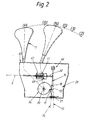
- a brake pedal 8 with its pedal lever 38 is mounted so as to be pivotable about a geometric pivot axis 36-36 on a bracket 62 installed in the footwell in front of the driver's seat in a motor vehicle in the usual manner.
- a return spring 13 in the form of a cylindrical helical spring which is subjected to tension and which actuates the brake pedal 8 in the direction of its drawn rest position 35 is suspended in the eyelets of one fastening tab 39 or 40 of the console 62 or of the pedal lever 38.
- the pedal lever 38 is connected by a uniaxial joint 5 to the usual brake linkage 4 leading to a master brake cylinder of the service brakes of the motor vehicle, which is thus actuated when the brake pedal 8 is depressed.
- a bearing pin 41 is fixed coaxially to a pivot axis 24-24 parallel to the pivot axis 36-36 of the brake pedal 8, on which a two-armed adjusting lever 16 for actuating one on a manual selector lever 7 one automatic switching device of a gear change provided locking device 20 is pivotally mounted.
- an actuator 19 On one lever arm 25 of the actuating lever 16 is an actuator 19 in the form of a cam with a Engagement surface 29 formed, which cooperates directly with an actuator 6 on the pedal lever 38 in a manner explained below.
- the actuator 6 has a roller cam 42 which can be brought into abutment directly on the engagement surface 29 and which is rotatably mounted on a bearing pin 43 which is fixed with its axis 44-44 parallel to the pivot axes 24-24 and 36-36 on the pedal lever 38.
- the engagement surface 29 is composed essentially of a radially inner section 45 which is closer to the pivot axis 24-24, an adjoining central section 46 and an adjoining radially outer section 47.
- the roller cam 42 engages with the central section 46 of the engagement surface 29, which extends transversely to the circular path 48 of the roller cam 42, so that when the brake pedal 8 has passed through a limited small swivel angle range 30 the actuating lever 16 is actuated in the direction of pivoting 28 acting in the sense of an unlocking with respect to the locking device 20.
- a locking spring 27 in the form of a cylindrical helical spring which is subjected to tension is suspended with its one spring end on an anchor bolt 22 which is fixedly held on the bearing bracket 62.
- the other spring end of the locking spring 27 is suspended in an eyelet of the other lever arm 26 of the actuating lever 16, wherein the anchor bolt 22 and the eyelet of the lever arm 26 are oriented to the pivot axis 24-24 that the locking spring 27 the actuating lever 16 in the sense of a Locking actuated with respect to the locking device 20 other pivoting direction 23.
- the lever arm 26 of the actuating lever 16 is formed in one piece with a fastening tab 49, which has a receptacle 50 in the form of a slotted opening, by means of which the one rod end 31 of an actuating rod 9 is articulated in the form of a cable on the lever arm 26, the articulation point bearing the reference number 72.
- the actuating linkage 9 leading to the locking device 20 is articulated with its relevant other linkage end 32 to a locking element 10 which is pivotably arranged between a locking position 14 and a free access position 15 by means of a joint 66 in the vicinity of the pivot axis 33 of the manual selector lever 7.
- the manual selector lever 7 is arranged in the manner of a middle circuit on the transmission tunnel 65 of the motor vehicle to the side of the driver's seat and is fixedly connected to a cam disk part 34 which can be rotated about the pivot axis 33.
- a locking cam 11 of the cam disk part 34 and a counter locking cam 12 of the locking element 10 are in the (P) position of the manual selector lever 7 - when the brake pedal 8 is in its rest position 35 - in such a way that an actuation of the manual selector lever 7 in one of the other positions (R), (N), (D), (3) or (2) locked - the lever 7 is thus locked (locking position 14 of the locking element 10).
- an unlocking spring 17 arranged in the vicinity of the locking element 10 is compressed between a spring stop in the form of a collar 68 and a spring abutment 67 which is fixed to the rod end 32 and is held under prestress.
- the manual selector lever 7 is unlocked by depressing the brake pedal 8 by a difference angle 51, the roller cam 6 being on the central section 46 of the engagement surface 29 by pivoting the adjusting lever 16 to Rolling reaches the outer portion 47 of the engagement surface 29 in the pedal position 53 and thereby has actuated the actuating lever 16 by a difference angle 69, so that the articulation point 72 of the actuating linkage 9 has moved from its illustrated locking position 70 into the position of an unlocking position 52 indicated at (72) is, which makes it possible for the unlocking spring 17 to actuate the locking element 10 into its free position 15 and thereby unlock the manual selector lever 7.
Claims (4)
- Dispositif installé sur une pédale de frein (8) utilisée pour actionner les freins de service d'un véhicule automobile, pour déverrouiller un levier (7) d'un dispositif de changement de vitesses d'une boîte de vitesses, dans lequel un premier organe d'actionnement (6) est monté, avec blocage contre tout déplacement, sur la pédale de frein (8) montée basculante, et un second organe d'actionnement (19) est monté, avec blocage contre tout déplacement, sur un levier de réglage (16) monté à proximité de la pédale de frein (8), pour bloquer et débloquer un dispositif de verrouillage (20) associé au levier (7) du dispositif de changement de vitesses, et un ressort de blocage (27), ancré ou prenant appui sur une partie solidaire du véhicule, attaque ou agit sur le levier de réglage (16), dans le sens d'un déblocage dans un sens de pivotement, et un organe d'actionnement associé (6) attaque ou agit sur le levier de réglage (16) dans le sens d'un déblocage dans le sens de pivotement opposé, caractérisé en ce que les deux organes d'actionnement (6 et 19) sont réalisés sous la forme de cames ou analogues et peuvent être amenés à engrener directement entre eux, et au moins le second organe d'actionnement (19) possède une surface d'engrènement (22) possédant une configuration telle que dans une plage angulaire limitée de pivotement (30), incluant la position de repos (35), de la pédale de frein (8), les forces résultantes apparaissant sur le premier organe d'actionnement (6) de la pédale de frein (8) soient situées au moins approximativement dans un plan (37-37), qui contient l'axe de pivotement (36-36) de la pédale de frein (8).
- Dispositif selon la revendication 1, caractérisé en ce que le ressort de blocage (27) est conçu de manière à produire des forces élastiques inférieures à celles d'un ressort de rappel (13) actionnant la pédale de frein (8) en direction de sa position de repos (35).
- Dispositif selon la revendication 1 ou 2, caractérisé en ce que le ressort de blocage (27) est conçu de manière à produire des forces élastiques supérieures à celles du ressort de déblocage (17), qui travaille dans le sens d'un déblocage, du dispositif de verrouillage conformément au brevet 38 42 333, et la configuration de la surface d'engrènement (29) amène les organes d'actionnement (6 et 19) à se dégager l'un de l'autre lorsque la pédale de frein (8) atteint sa position de repos (35) et que le dispositif de verrouillage (20) est débloqué.
- Dispositif selon l'une des revendications 1 à 3, caractérisé en ce que la configuration de la surface d'engrènement (29) est agencée de telle sorte que dans une plage angulaire limitée de pivotement (54) de la pédale de frein (8), qui se raccorde à la position (53) de la pédale de frein (8), qui correspond à l'état débloqué (position d'actionnement libre (15) du dispositif de verrouillage (20), les organes d'actionnement (6 et 19) continuent à être maintenus dans un état d'engrènement réciproque moyennant le maintien à une faible valeur des moments de levier qui sont appliqués à la pédale de frein (8).
Applications Claiming Priority (2)
| Application Number | Priority Date | Filing Date | Title |
|---|---|---|---|
| DE4023876A DE4023876C1 (fr) | 1990-07-27 | 1990-07-27 | |
| DE4023876 | 1990-07-27 |
Publications (2)
| Publication Number | Publication Date |
|---|---|
| EP0468152A1 EP0468152A1 (fr) | 1992-01-29 |
| EP0468152B1 true EP0468152B1 (fr) | 1994-07-27 |
Family
ID=6411124
Family Applications (1)
| Application Number | Title | Priority Date | Filing Date |
|---|---|---|---|
| EP91107553A Expired - Lifetime EP0468152B1 (fr) | 1990-07-27 | 1991-05-09 | Dispositif sur une pédale de frein pour bloquer et débloquer le levier du dispositif de changement de vitesse dans une transmission de véhicule |
Country Status (4)
| Country | Link |
|---|---|
| US (1) | US5161657A (fr) |
| EP (1) | EP0468152B1 (fr) |
| JP (1) | JPH07112794B2 (fr) |
| DE (1) | DE4023876C1 (fr) |
Families Citing this family (10)
| Publication number | Priority date | Publication date | Assignee | Title |
|---|---|---|---|---|
| US5862899A (en) * | 1997-03-10 | 1999-01-26 | Ut Automotive Dearborn, Inc. | Brake-shift interlock |
| US5860303A (en) * | 1997-08-29 | 1999-01-19 | Teleflex Incorporated | Ignition safety interlock |
| FR2780474B1 (fr) * | 1998-06-26 | 2000-09-08 | Peugeot | Dispositif mecanique de blocage du levier de commande d'une boite de vitesses automatique pour vehicule automobile |
| US6295892B1 (en) * | 1999-07-09 | 2001-10-02 | Soucy International Inc. | Lockable lever arm assembly |
| US6913104B2 (en) * | 2003-02-26 | 2005-07-05 | Mtd Products Inc | Shift interlock mechanism |
| US7278526B2 (en) * | 2004-04-23 | 2007-10-09 | Delphi Technologies, Inc. | Integrated position switch/brake transmission shift interlock for electronic gear indication |
| JP4394031B2 (ja) * | 2005-04-12 | 2010-01-06 | 豊田鉄工株式会社 | ブレーキペダル装置 |
| JP4486617B2 (ja) * | 2006-06-05 | 2010-06-23 | 豊田鉄工株式会社 | ブレーキペダル装置 |
| WO2008120238A1 (fr) * | 2007-03-29 | 2008-10-09 | Tata Motors Limited | Mécanisme perfectionné de changement de vitesse pour transmission automatique d'un véhicule |
| CN103982640B (zh) * | 2014-04-28 | 2016-03-09 | 于浩 | 一种档位弹簧手握式旋片 |
Family Cites Families (7)
| Publication number | Priority date | Publication date | Assignee | Title |
|---|---|---|---|---|
| US2908785A (en) * | 1958-05-19 | 1959-10-13 | Rickert Electric Inc | Electromagnetic device |
| US4096930A (en) * | 1977-08-05 | 1978-06-27 | Frank Viscardi | Gear shift selector brake interlock |
| FR2467100A1 (fr) * | 1979-10-12 | 1981-04-17 | Girard Selecteur | Dispositif de remise au point mort pour engin a transmission hydrostatique |
| US4421214A (en) * | 1980-12-16 | 1983-12-20 | Gulf & Western Industries, Inc. | System for automatically releasing parking brakes |
| US4572340A (en) * | 1983-05-20 | 1986-02-25 | Pierce Kenneth E | Safety lock vehicle transmission |
| DE3419168A1 (de) * | 1984-05-23 | 1985-11-28 | Wabco Westinghouse Fahrzeugbremsen GmbH, 3000 Hannover | Sperrvorrichtung fuer einen handbetaetigten gangwaehler |
| DE3842333C1 (fr) * | 1988-12-16 | 1990-04-12 | Daimler-Benz Aktiengesellschaft, 7000 Stuttgart, De |
-
1990
- 1990-07-27 DE DE4023876A patent/DE4023876C1/de not_active Expired - Lifetime
-
1991
- 1991-05-09 EP EP91107553A patent/EP0468152B1/fr not_active Expired - Lifetime
- 1991-06-19 US US07/717,499 patent/US5161657A/en not_active Expired - Lifetime
- 1991-06-20 JP JP3174726A patent/JPH07112794B2/ja not_active Expired - Fee Related
Also Published As
| Publication number | Publication date |
|---|---|
| DE4023876C1 (fr) | 1992-01-23 |
| EP0468152A1 (fr) | 1992-01-29 |
| JPH04232131A (ja) | 1992-08-20 |
| JPH07112794B2 (ja) | 1995-12-06 |
| US5161657A (en) | 1992-11-10 |
Similar Documents
| Publication | Publication Date | Title |
|---|---|---|
| DE3839117C2 (fr) | ||
| EP0097369B1 (fr) | Dispositif de changement de marche pour une transmission | |
| DE10102685A1 (de) | Betätigungsmechanismus mit Kraftsensor für eine Bremse | |
| EP0373368B1 (fr) | Dispositif pour verrouiller un levier de changement de vitesse dans une position correspondant à un rapport ou d'une programmation de rapports dépendant d'une pédale de frein | |
| DE4211566A1 (de) | Mit einer selbsttätigen Nachstelleinrichtung versehene Handbremse | |
| DE2328230B2 (de) | Insbesondere zum Schalten eines Wechselgetriebes bestimmtes Übertragungsgestänge für Fahrzeuge, insbesondere Nutzfahrzeuge, mit kippbaren Fahrerhäusern | |
| EP0468152B1 (fr) | Dispositif sur une pédale de frein pour bloquer et débloquer le levier du dispositif de changement de vitesse dans une transmission de véhicule | |
| DE3010409C2 (de) | Umspannvorrichtung für ein Kupplungspedal | |
| DE102018107492A1 (de) | Verbesserter Klappmechanismus für einen Elektroroller | |
| EP0869888A1 (fr) | Frein de stationnement pour vehicules a moteur, remorques de vehicules ou similaires | |
| DE3511871C2 (fr) | ||
| EP0261660B1 (fr) | Frein de roue pour remorque | |
| DE3741530C2 (fr) | ||
| DE19811094C2 (de) | Längsverstellvorrichtung für einen Sitz, insbesondere Kraftfahrzeugsitz | |
| EP0904223B1 (fr) | Regulateur d'ajustement automatique de la longueur d'une corroie d'actionnement | |
| EP0933271B1 (fr) | Frein à main muni d'un dispositif de rattrapage automatique pour véhicules automobiles | |
| DE19726188B4 (de) | Feststellbremse für Kraftfahrzeuge | |
| DE2438755A1 (de) | Selbsttaetig nachstellbare bremsbandanordnung | |
| DE2606925C3 (de) | Selbsttätige Nachstellvorrichtung für die Bremsbacken einer Innenbackenbremse | |
| DE3304593C2 (de) | Nachstell- und Zentriervorrichtung für Servobremsen | |
| EP0968869B1 (fr) | Moissonneuse agricole autopropulsée | |
| DE2140611B2 (de) | Schalt- und Lenk-Bremsbetätigungsvorrichtung, insbesondere für Kraftfahrzeuge mit nicht schwenkbaren Rädern bzw. Gleisketten | |
| WO2001074628A1 (fr) | Ensemble pedale atraumatique | |
| DE10030275B4 (de) | Rastmechanismus für einen Fahrtrichtungsschalter eines Kraftfahrzeugs | |
| DE19841750A1 (de) | Sicherheitsgurtsystem für ein Kraftfahrzeug |
Legal Events
| Date | Code | Title | Description |
|---|---|---|---|
| PUAI | Public reference made under article 153(3) epc to a published international application that has entered the european phase |
Free format text: ORIGINAL CODE: 0009012 |
|
| 17P | Request for examination filed |
Effective date: 19911025 |
|
| AK | Designated contracting states |
Kind code of ref document: A1 Designated state(s): FR GB IT SE |
|
| 17Q | First examination report despatched |
Effective date: 19930811 |
|
| GRAA | (expected) grant |
Free format text: ORIGINAL CODE: 0009210 |
|
| ITF | It: translation for a ep patent filed |
Owner name: BARZANO' E ZANARDO ROMA S.P.A. |
|
| AK | Designated contracting states |
Kind code of ref document: B1 Designated state(s): FR GB IT SE |
|
| GBT | Gb: translation of ep patent filed (gb section 77(6)(a)/1977) |
Effective date: 19940815 |
|
| ET | Fr: translation filed | ||
| EAL | Se: european patent in force in sweden |
Ref document number: 91107553.9 |
|
| PLBE | No opposition filed within time limit |
Free format text: ORIGINAL CODE: 0009261 |
|
| STAA | Information on the status of an ep patent application or granted ep patent |
Free format text: STATUS: NO OPPOSITION FILED WITHIN TIME LIMIT |
|
| 26N | No opposition filed | ||
| REG | Reference to a national code |
Ref country code: FR Ref legal event code: TP |
|
| REG | Reference to a national code |
Ref country code: GB Ref legal event code: 732E |
|
| REG | Reference to a national code |
Ref country code: GB Ref legal event code: 732E |
|
| PGFP | Annual fee paid to national office [announced via postgrant information from national office to epo] |
Ref country code: GB Payment date: 20010412 Year of fee payment: 11 |
|
| PGFP | Annual fee paid to national office [announced via postgrant information from national office to epo] |
Ref country code: SE Payment date: 20010503 Year of fee payment: 11 |
|
| REG | Reference to a national code |
Ref country code: GB Ref legal event code: IF02 |
|
| PG25 | Lapsed in a contracting state [announced via postgrant information from national office to epo] |
Ref country code: GB Free format text: LAPSE BECAUSE OF NON-PAYMENT OF DUE FEES Effective date: 20020509 |
|
| PG25 | Lapsed in a contracting state [announced via postgrant information from national office to epo] |
Ref country code: SE Free format text: LAPSE BECAUSE OF NON-PAYMENT OF DUE FEES Effective date: 20020510 |
|
| GBPC | Gb: european patent ceased through non-payment of renewal fee |
Effective date: 20020509 |
|
| EUG | Se: european patent has lapsed | ||
| PG25 | Lapsed in a contracting state [announced via postgrant information from national office to epo] |
Ref country code: IT Free format text: LAPSE BECAUSE OF NON-PAYMENT OF DUE FEES;WARNING: LAPSES OF ITALIAN PATENTS WITH EFFECTIVE DATE BEFORE 2007 MAY HAVE OCCURRED AT ANY TIME BEFORE 2007. THE CORRECT EFFECTIVE DATE MAY BE DIFFERENT FROM THE ONE RECORDED. Effective date: 20050509 |
|
| PGFP | Annual fee paid to national office [announced via postgrant information from national office to epo] |
Ref country code: FR Payment date: 20050512 Year of fee payment: 15 |
|
| REG | Reference to a national code |
Ref country code: FR Ref legal event code: ST Effective date: 20070131 |
|
| PG25 | Lapsed in a contracting state [announced via postgrant information from national office to epo] |
Ref country code: FR Free format text: LAPSE BECAUSE OF NON-PAYMENT OF DUE FEES Effective date: 20060531 |