EP0468152B1 - Brake pedal arrangement for locking/unlocking a lever of a vehicle gear shifting device - Google Patents
Brake pedal arrangement for locking/unlocking a lever of a vehicle gear shifting device Download PDFInfo
- Publication number
- EP0468152B1 EP0468152B1 EP91107553A EP91107553A EP0468152B1 EP 0468152 B1 EP0468152 B1 EP 0468152B1 EP 91107553 A EP91107553 A EP 91107553A EP 91107553 A EP91107553 A EP 91107553A EP 0468152 B1 EP0468152 B1 EP 0468152B1
- Authority
- EP
- European Patent Office
- Prior art keywords
- brake pedal
- locking
- lever
- actuating
- spring
- Prior art date
- Legal status (The legal status is an assumption and is not a legal conclusion. Google has not performed a legal analysis and makes no representation as to the accuracy of the status listed.)
- Expired - Lifetime
Links
Images


Classifications
-
- B—PERFORMING OPERATIONS; TRANSPORTING
- B60—VEHICLES IN GENERAL
- B60T—VEHICLE BRAKE CONTROL SYSTEMS OR PARTS THEREOF; BRAKE CONTROL SYSTEMS OR PARTS THEREOF, IN GENERAL; ARRANGEMENT OF BRAKING ELEMENTS ON VEHICLES IN GENERAL; PORTABLE DEVICES FOR PREVENTING UNWANTED MOVEMENT OF VEHICLES; VEHICLE MODIFICATIONS TO FACILITATE COOLING OF BRAKES
- B60T7/00—Brake-action initiating means
- B60T7/02—Brake-action initiating means for personal initiation
- B60T7/04—Brake-action initiating means for personal initiation foot actuated
-
- F—MECHANICAL ENGINEERING; LIGHTING; HEATING; WEAPONS; BLASTING
- F16—ENGINEERING ELEMENTS AND UNITS; GENERAL MEASURES FOR PRODUCING AND MAINTAINING EFFECTIVE FUNCTIONING OF MACHINES OR INSTALLATIONS; THERMAL INSULATION IN GENERAL
- F16H—GEARING
- F16H59/00—Control inputs to control units of change-speed-, or reversing-gearings for conveying rotary motion
- F16H59/02—Selector apparatus
- F16H59/08—Range selector apparatus
- F16H59/10—Range selector apparatus comprising levers
-
- F—MECHANICAL ENGINEERING; LIGHTING; HEATING; WEAPONS; BLASTING
- F16—ENGINEERING ELEMENTS AND UNITS; GENERAL MEASURES FOR PRODUCING AND MAINTAINING EFFECTIVE FUNCTIONING OF MACHINES OR INSTALLATIONS; THERMAL INSULATION IN GENERAL
- F16H—GEARING
- F16H59/00—Control inputs to control units of change-speed-, or reversing-gearings for conveying rotary motion
- F16H59/50—Inputs being a function of the status of the machine, e.g. position of doors or safety belts
- F16H59/54—Inputs being a function of the status of the machine, e.g. position of doors or safety belts dependent on signals from the brakes, e.g. parking brakes
-
- F—MECHANICAL ENGINEERING; LIGHTING; HEATING; WEAPONS; BLASTING
- F16—ENGINEERING ELEMENTS AND UNITS; GENERAL MEASURES FOR PRODUCING AND MAINTAINING EFFECTIVE FUNCTIONING OF MACHINES OR INSTALLATIONS; THERMAL INSULATION IN GENERAL
- F16H—GEARING
- F16H61/00—Control functions within control units of change-speed- or reversing-gearings for conveying rotary motion ; Control of exclusively fluid gearing, friction gearing, gearings with endless flexible members or other particular types of gearing
- F16H61/22—Locking of the control input devices
-
- Y—GENERAL TAGGING OF NEW TECHNOLOGICAL DEVELOPMENTS; GENERAL TAGGING OF CROSS-SECTIONAL TECHNOLOGIES SPANNING OVER SEVERAL SECTIONS OF THE IPC; TECHNICAL SUBJECTS COVERED BY FORMER USPC CROSS-REFERENCE ART COLLECTIONS [XRACs] AND DIGESTS
- Y10—TECHNICAL SUBJECTS COVERED BY FORMER USPC
- Y10T—TECHNICAL SUBJECTS COVERED BY FORMER US CLASSIFICATION
- Y10T74/00—Machine element or mechanism
- Y10T74/20—Control lever and linkage systems
- Y10T74/20012—Multiple controlled elements
- Y10T74/20018—Transmission control
- Y10T74/20085—Restriction of shift, gear selection, or gear engagement
- Y10T74/20104—Shift element interlock
- Y10T74/20116—Resiliently biased interlock
-
- Y—GENERAL TAGGING OF NEW TECHNOLOGICAL DEVELOPMENTS; GENERAL TAGGING OF CROSS-SECTIONAL TECHNOLOGIES SPANNING OVER SEVERAL SECTIONS OF THE IPC; TECHNICAL SUBJECTS COVERED BY FORMER USPC CROSS-REFERENCE ART COLLECTIONS [XRACs] AND DIGESTS
- Y10—TECHNICAL SUBJECTS COVERED BY FORMER USPC
- Y10T—TECHNICAL SUBJECTS COVERED BY FORMER US CLASSIFICATION
- Y10T74/00—Machine element or mechanism
- Y10T74/20—Control lever and linkage systems
- Y10T74/20576—Elements
- Y10T74/20636—Detents
- Y10T74/20666—Lever engaging
Description
Die Erfindung bezieht sich auf eine Anordnung nach dem Oberbegriff von Patentanspruch 1.The invention relates to an arrangement according to the preamble of claim 1.
Bei einer bekannten Anordnung dieser Art (US-A- 45 72 340) arbeitet das Bremspedal über ein an die Bremshydraulik angeschlossenes hydrostatisches Gestänge zusammen mit der Verriegelungsfeder auf den einen Hebelarm des zweiarmig ausgebildeten Stellhebels, dessen anderer Hebelarm korrespondierende Ausnehmungen für die jeweilige Verriegelung der drei Stellungen eines Riegels aufweist, welcher starr an einem Schalthebel einer Schaltvorrichtung eines in eine Neutralstellung und jeweils eine weitere Stellung für Vorwärts- und Rückwärtsfahrt schaltbaren Getriebes angeordnet ist, so daß diese Verriegelungsvorrichtung bei jeder Getriebeschaltung durch das Bremspedal entriegelt werden muß. Infolge der ständigen hydraulischen Ankoppelung des Stellhebels an das Bremspedal ergibt sich ein störender Einfluß durch die Verriegelungsfeder, wenn relativ niedrige fein dosierte Bremskräfte eingesteuert werden sollen.In a known arrangement of this type (US-A-45 72 340), the brake pedal works via a hydrostatic linkage connected to the brake hydraulics together with the locking spring on one lever arm of the two-arm control lever, the other lever arm corresponding recesses for the respective locking of the three Has positions of a bolt, which is rigidly arranged on a shift lever of a switching device of a gear in a neutral position and in each case a further position for forward and reverse travel, so that this locking device must be unlocked by the brake pedal with each gear shift. As a result of the constant hydraulic coupling of the control lever to the brake pedal, there is a disruptive influence by the locking spring when relatively low, finely metered braking forces are to be applied.
Die der Erfindung zugrunde liegende Aufgabe besteht in wesentlichen darin, bei einer gattungsgemäßen Anordnung hydraulische Mittel zur Verriegelung des Hebels der Schaltvorrichtung, insbesondere des Handwählhebels einer selbsttätigen Schaltvorrichtung aus Sicherheitsgründen zu vermeiden und unerwünschte Einflüsse der Verriegelungsfeder bei der Einsteuerung von niedrigen Bremskräften gering zu halten bzw. zu verhindern.The task underlying the invention essentially consists in a generic arrangement hydraulic means for locking the lever of the switching device, in particular the manual selector lever of an automatic Avoid switching device for safety reasons and to keep or prevent undesirable influences of the locking spring when applying low braking forces.
Die erläuterte Aufgabe ist in vorteilhafter Weise mit den kennzeichnenden Merkmalen von Patentanspruch 1 gelöst.The object explained is advantageously achieved with the characterizing features of patent claim 1.
Die erfindungsgemäße Anordnung eignet sich besonders für solche Verriegelungsvorrichtungen, bei denen der Hebel der Schaltvorrichtung nur in einer - bei einem Handwählhebel also in der P-Stellung - blockierbar und in den übrigen Stellungen eine Nockensteuerung der Verriegelungsvorrichtung am Stellhebel wirksam ist, welche die Verriegelungsfeder an sich unter Spannung hält - durch die Erfindung in ihrem Einfluß auf das Bremspedal auch in dem angesprochenen engen Schwenkwinkelbereich abgeschaltet ist. Bei Anwendung der Erfindung auf derartige Anordnungen - bspw. nach dem deutschen Patent DE-C- 38 42 333 - ist dann die Federabstimmung zwischen den drei zur Anwendung kommenden Federn nach den Patentansprüchen 2 und 3 getroffen.The arrangement according to the invention is particularly suitable for locking devices in which the lever of the switching device can only be blocked in one - in the case of a manual selector lever in the P position - and in the other positions a cam control of the locking device on the adjusting lever is effective, which is the locking spring itself keeps under tension - is switched off by the invention in its influence on the brake pedal even in the narrow swivel angle range mentioned. When the invention is applied to such arrangements - for example according to the German patent DE-C-38 42 333 - the spring coordination between the three springs used according to
Die Anordnung nach der Erfindung ist in vorteilhafter Weise mit der Ausgestaltung nach Patentanspruch 4 spielfrei gehalten.The arrangement according to the invention is advantageously kept free of play with the configuration according to claim 4.
Einzelheiten der Erfindung ergeben sich aus der nachstehenden Beschreibung eines in der Zeichnung schematisch dargestellten Ausführungsbeispieles. In der Zeichnung bedeuten
- Figur 1
- eine schematische Darstellung eines Bremspedales eines Kraftfahrzeuges mit einer Anordnung nach der Erfindung zum Ent- und Verriegeln eines Wählhebels einer selbsttätigen Schaltvorrichtung eines Gangwechselgetriebes,
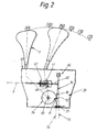
Figur 2- eine schematische Darstellung einer durch die Anordnung nach der Erfindung von Figur 1 betätigbaren Verriegelungsvorrichtung nach
Patent 38 42 333, und Figur 3- einen Schnitt durch die Anordnung von Figur 1 nach Linie III-III.
- Figure 1
- 1 shows a schematic illustration of a brake pedal of a motor vehicle with an arrangement according to the invention for unlocking and locking a selector lever of an automatic shifting device of a gear change transmission,
- Figure 2
- 2 shows a schematic illustration of a locking device according to
patent 38 42 333 which can be actuated by the arrangement according to the invention from FIG. 1, and - Figure 3
- a section through the arrangement of Figure 1 along line III-III.
An einer im Fußraum vor dem Fahrersitz in einem Kraftfahrzeug in der üblichen Weise bewegungsfest installierten Konsole 62 ist ein Bremspedal 8 mit seinem Pedalhebel 38 um eine geometrische Schwenkachse 36-36 schwenkbar gelagert. In den Ösen je einer Befestigungslasche 39 bzw. 40 der Konsole 62 bzw. des Pedalhebels 38 ist eine Rückholfeder 13 in Form einer auf Zug beanspruchten zylindrischen Schraubenfeder eingehängt, welche das Bremspedal 8 in Richtung seiner gezeichneten Ruhestellung 35 betätigt.A
In dem zwischen seiner Schwenkachse 36-36 und seiner Befestigungslasche 40 liegenden Bereich ist der Pedalhebel 38 durch ein einachsiges Gelenk 5 mit dem üblichen zu einem Hauptbrems-Zylinder der Betriebsbremsen des Kraftfahrzeuges führenden Bremsgestänge 4 verbunden, welches somit beim Niedertreten des Bremspedales 8 betätigt wird.In the area between its pivot axis 36-36 and its
An einem in Nähe des Pedalhebels 38 liegenden Konsolenteil 63 der Lagerkonsole 62 ist ein Lagerbolzen 41 koaxial zu einer zur Schwenkachse 36-36 des Bremspedales 8 parallelen Schwenkachse 24-24 feststehend gehaltert, auf welchem ein zweiarmiger Stellhebel 16 zur Betätigung einer an einem Handwählhebel 7 einer selbsttätigen Schaltvorrichtung eines Gangwechselgetriebes vorgesehenen Verriegelungsvorrichtung 20 schwenkbar gelagert ist. An dem einen Hebelarm 25 des Stellhebels 16 ist ein Betätigungsglied 19 in Form eines Nockens mit einer Eingriffsfläche 29 ausgebildet, welche unmittelbar mit einem Betätigungsglied 6 am Pedalhebel 38 in weiter unten erläuterter Weise zusammenarbeitet. Das Betätigungsglied 6 weist einen unmittelbar an der Eingriffsfläche 29 zur Anlage bringbaren Rollnocken 42 auf, welcher auf einem mit seiner Achse 44-44 parallel zu den Schwenkachsen 24-24 und 36-36 am Pedalhebel 38 feststehend gehalterten Lagerzapfen 43 drehbar gelagert ist. Die Eingriffsfläche 29 setzt sich im wesentlichen aus einem näher zur Schwenkachse 24-24 liegenden radial inneren Abschnitt 45, aus einem sich anschließenden mittleren Abschnitt 46 sowie aus einem sich anschließenden radial äußeren Abschnitt 47 zusammen.On a
Beim Niedertreten des Bremspedales 8 aus der Ruhestellung 35 heraus gelangt der Rollnocken 42 - wenn das Bremspedal 8 einen begrenzten kleinen Schwenkwinkelbereich 30 durchlaufen hat - mit dem mittleren Abschnitt 46 der Eingriffsfläche 29 in Eingriff, welcher quer zur Kreisbahn 48 des Rollnockens 42 verläuft, so daß der Stellhebel 16 in dem im Sinne einer Entriegelung in bezug auf die Verriegelungsvorrichtung 20 wirkenden Schwenksinn 28 betätigt wird.When the
Eine auf Zug beanspruchte Verriegelungsfeder 27 in Form einer zylindrischen Schraubenfeder ist mit ihrem einen Federende an einem feststehend an der Lagerkonsole 62 gehalterten Ankerbolzen 22 eingehängt. Das andere Federende der Verriegelungsfeder 27 ist in eine Öse des anderen Hebelarmes 26 des Stellhebels 16 eingehängt, wobei der Ankerbolzen 22 und die Öse des Hebelarmes 26 so zur Schwenkachse 24-24 orientiert sind, daß die Verriegelungsfeder 27 den Stellhebel 16 in dem im Sinne einer Verriegelung in bezug auf die Verriegelungsvorrichtung 20 wirkenden anderen Schwenksinn 23 betätigt.A
In seinem zwischen der Öse für die Verriegelungsfeder 27 und der Schwenkachse 24-24 liegenden Bereich ist der Hebelarm 26 des Stellhebels 16 mit einer Befestigungslasche 49 einteilig ausgebildet, welche eine Aufnahme 50 in Form einer geschlitzten Öffnung aufweist, mittels der das eine Gestängeende 31 eines Stellgestänges 9 in Form eines Seilzuges am Hebelarm 26 angelenkt ist, wobei der Anlenkpunkt die Bezugszahl 72 trägt.In its area between the eyelet for the
Das zu der Verriegelungsvorrichtung 20 führende Stellgestänge 9 ist mit seinem diesbezüglichen anderen Gestängeende 32 an einem Riegelelement 10 angelenkt, welches zwischen einer Verriegelungsstellung 14 und einer Freigangstellung 15 schwenkbar mittels eines Gelenkes 66 in Nähe der Schwenkachse 33 des Handwählhebels 7 angeordnet ist. Der Handwählhebel 7 ist nach Art einer Mittelschaltung am Getriebetunnel 65 des Kraftfahrzeuges seitlich zum Fahrersitz angeordnet und fest mit einem um die Schwenkachse 33 drehbaren Nockenscheibenteil 34 verbunden. Ein Sperrnocken 11 des Nockenscheibenteiles 34 und ein Gegensperrnocken 12 des Riegelelementes 10 stehen in der (P)-Stellung des Handwählhebels 7 - wenn sich das Bremspedal 8 in seiner Ruhestellung 35 befindet - so miteinander in Eingriff, daß eine Betätigung des Handwählhebels 7 in eine der anderen Stellungen (R), (N), (D), (3) oder (2) gesperrt - der Hebel 7 somit verriegelt ist (Verriegelungsstellung 14 des Riegelelementes 10). Hierbei ist eine in Nähe des Riegelelementes 10 angeordnete Entriegelungsfeder 17 zwischen einem fest am Gestängeende 32 sitzenden Federanschlag in Form eines Bundes 68 und einem fahrzeugfesten Federwiderlager 67 eingefedert und unter Vorspannung gehalten.The actuating
Eine Entriegelung des Handwählhebels 7 erfolgt durch Niedertreten des Bremspedales 8 um einen Differenzwinkel 51, wobei der Rollnocken 6 sich auf dem mittleren Abschnitt 46 der Eingriffsfläche 29 unter Verschwenken des Stellhebels 16 bis zum Erreichen des äußeren Abschnittes 47 der Eingriffsfläche 29 in der Pedalstellung 53 abwälzt und dadurch den Stellhebel 16 um einen Differenzwinkel 69 betätigt hat, so daß der Anlenkpunkt 72 des Stellgestänges 9 aus seiner gezeichneten Verriegelungsstellung 70 in die bei (72) angedeutete Lage einer Entriegelungsstellung 52 gewandert ist, wodurch es der Entriegelungsfeder 17 ermöglicht ist, das Riegelelement 10 in seine Freigangstellung 15 zu betätigen und dadurch den Handwählhebel 7 zu entriegeln. Wird der auf diese Weise entriegelte Handwählhebel 7 aus der (P)-Stellung in eine der Wählbereichsstellungen (R), (N), (D), (3) oder (2) betätigt, gelangen eine Steuernockenfläche 18 des Nockenscheibenteiles 34 und eine Gegensteuernockenfläche 21 am Riegelelement 10 so in Eingriff, daß das Riegelelement 10 in seine Freigangstellung 15 betätigt bleibt, so daß das angekoppelte Stellgestänge 9 den Stellhebel 16 in der Entriegelungsstellung 52 hält, in welcher die Betätigungsglieder 6 und 19 voneinander abgehoben haben, also außer Eingriff sind. Dadurch sind die aus der Betätigung der Verriegelungsvorrichtung 20 durch die Verriegelungsfeder 27 und durch die Nocken 18, 21 resultierenden Kräfte ohne Einfluß auf Bremspedal 8 und Rückholfeder 13.The manual selector lever 7 is unlocked by depressing the
In der Ruhestellung 35 und in dem sich anschließenden Schwenkwinkelbereich 30 des Bremspedales 8 sind die vom Stellhebel 16 am Rollnocken 6 ausgeübten Kräfte in ihrer Wirkung auf die Rückholfeder 13 dadurch gering gehalten, daß die entsprechenden Hebelmomente um die Schwenkachse 36-36 gegen Null ausgelegt sind, d. h., der Abschnitt 45 der Eingriffsfläche 29 verläuft in etwa tangential zu der Kreisbahn 55 des Eingriffspunktes am Rollnocken 6 um die Schwenkachse 36-36, wobei die erwähnten Kräfte dann etwa in einer die Schwenkachse 36-36 enthaltenden Ebene 35-35 wirken.In the
Ähnlich ist der Verlauf des äußeren Abschnittes 47 der Eingriffsfläche 29 zu der genannten Kreisbahn 55 gehalten, jedoch mit einer von der Tangentialen etwas stärkeren Abweichung derart, daß die Eingriffsglieder 6 und 19 unter Geringhaltung der resultierenden Kräfte noch mit Sicherheit in gegenseitigem Eingriff verbleiben, wenn das Bremspedal 8 über die Pedalstellung 53 hinaus niedergetreten wird.Similarly, the course of the outer portion 47 of the
Claims (4)
- Arrangement on a brake pedal (8), used for actuating the operating brakes of a motor vehicle, for releasing a lever (7) of a shift device of a change gear, in which a first actuating member (6) is arranged fixedly in terms of movement on the pivotably mounted brake pedal (8) and a second actuating member (19) is arranged fixedly in terms of movement on an adjusting lever (16) mounted in the vicinity of the brake pedal (8), said members being for locking and releasing a locking device (20) assigned to the lever (7) of the shift device, and a locking spring (27) anchored or supported on a part fixed to the vehicle engages or is effective on the adjusting lever (16) in one pivoting direction with the effect of a locking and an associated actuating member (6) engages or is effective on the adjusting lever in the opposite pivoting direction with the effect of a release, characterised in that the two actuating members (6 and 19) are designed in the form of cams or the like and can be brought directly into engagement with one another, and at least the second actuating member (19) has an engagement surface (29) of such a shape that, in a limited pivot-angle range (30) of the brake pedal (8) including the position of rest (35), the forces resulting on the first actuating member (6) of the brake pedal (8) are at least approximately in a plane (37-37) containing the pivot axis (36-36) of the brake pedal (8).
- Arrangement according to Claim 1, characterised in that the locking spring (27) is designed with lower spring forces than a return spring (13) actuating the brake pedal (8) in the direction of its position of rest (35).
- Arrangement according to Claim 1 or 2, characterised in that the locking spring (27) is designed with higher spring forces than the release spring (17) working with the effect of a release and belonging to the locking device according to Patent 3,842,333, and the shape of the engagement surface (29) causes the actuating members (6 and 19) to come out of engagement when the brake pedal (8) assumes its position of rest (35) and the locking device (20) is released.
- Arrangement according to one of Claims 1 to 3, characterised in that the shape of the engagement surface (29) is so designed that, in a limited pivot-angle range (54) of the brake pedal (8) adjacent to that pedal position (53) of the brake pedal (8) which corresponds to the released state (free position 15) of the locking device (20), the actuating members (6 and 19) are maintained in further mutual engagement, with the lever moments resulting on the brake pedal (8) being kept low.
Applications Claiming Priority (2)
| Application Number | Priority Date | Filing Date | Title |
|---|---|---|---|
| DE4023876A DE4023876C1 (en) | 1990-07-27 | 1990-07-27 | |
| DE4023876 | 1990-07-27 |
Publications (2)
| Publication Number | Publication Date |
|---|---|
| EP0468152A1 EP0468152A1 (en) | 1992-01-29 |
| EP0468152B1 true EP0468152B1 (en) | 1994-07-27 |
Family
ID=6411124
Family Applications (1)
| Application Number | Title | Priority Date | Filing Date |
|---|---|---|---|
| EP91107553A Expired - Lifetime EP0468152B1 (en) | 1990-07-27 | 1991-05-09 | Brake pedal arrangement for locking/unlocking a lever of a vehicle gear shifting device |
Country Status (4)
| Country | Link |
|---|---|
| US (1) | US5161657A (en) |
| EP (1) | EP0468152B1 (en) |
| JP (1) | JPH07112794B2 (en) |
| DE (1) | DE4023876C1 (en) |
Families Citing this family (10)
| Publication number | Priority date | Publication date | Assignee | Title |
|---|---|---|---|---|
| US5862899A (en) * | 1997-03-10 | 1999-01-26 | Ut Automotive Dearborn, Inc. | Brake-shift interlock |
| US5860303A (en) * | 1997-08-29 | 1999-01-19 | Teleflex Incorporated | Ignition safety interlock |
| FR2780474B1 (en) * | 1998-06-26 | 2000-09-08 | Peugeot | MECHANICAL DEVICE FOR LOCKING THE CONTROL LEVER OF AN AUTOMATIC TRANSMISSION FOR A MOTOR VEHICLE |
| US6295892B1 (en) * | 1999-07-09 | 2001-10-02 | Soucy International Inc. | Lockable lever arm assembly |
| US6913104B2 (en) * | 2003-02-26 | 2005-07-05 | Mtd Products Inc | Shift interlock mechanism |
| US7278526B2 (en) * | 2004-04-23 | 2007-10-09 | Delphi Technologies, Inc. | Integrated position switch/brake transmission shift interlock for electronic gear indication |
| JP4394031B2 (en) * | 2005-04-12 | 2010-01-06 | 豊田鉄工株式会社 | Brake pedal device |
| JP4486617B2 (en) * | 2006-06-05 | 2010-06-23 | 豊田鉄工株式会社 | Brake pedal device |
| WO2008120238A1 (en) * | 2007-03-29 | 2008-10-09 | Tata Motors Limited | Improved gear shifting mechanism for automatic transmission of a vehicle |
| CN103982640B (en) * | 2014-04-28 | 2016-03-09 | 于浩 | A kind of gear hand spring drot gfasplng blade |
Family Cites Families (7)
| Publication number | Priority date | Publication date | Assignee | Title |
|---|---|---|---|---|
| US2908785A (en) * | 1958-05-19 | 1959-10-13 | Rickert Electric Inc | Electromagnetic device |
| US4096930A (en) * | 1977-08-05 | 1978-06-27 | Frank Viscardi | Gear shift selector brake interlock |
| FR2467100A1 (en) * | 1979-10-12 | 1981-04-17 | Girard Selecteur | Engine brake transmission returning device to neutral - uses moving pivot to shift linkages in transmission selection which is normally locked but rotates when brake is applied |
| US4421214A (en) * | 1980-12-16 | 1983-12-20 | Gulf & Western Industries, Inc. | System for automatically releasing parking brakes |
| US4572340A (en) * | 1983-05-20 | 1986-02-25 | Pierce Kenneth E | Safety lock vehicle transmission |
| DE3419168A1 (en) * | 1984-05-23 | 1985-11-28 | Wabco Westinghouse Fahrzeugbremsen GmbH, 3000 Hannover | Locking device for a manually operated gear selector |
| DE3842333C1 (en) * | 1988-12-16 | 1990-04-12 | Daimler-Benz Aktiengesellschaft, 7000 Stuttgart, De |
-
1990
- 1990-07-27 DE DE4023876A patent/DE4023876C1/de not_active Expired - Lifetime
-
1991
- 1991-05-09 EP EP91107553A patent/EP0468152B1/en not_active Expired - Lifetime
- 1991-06-19 US US07/717,499 patent/US5161657A/en not_active Expired - Lifetime
- 1991-06-20 JP JP3174726A patent/JPH07112794B2/en not_active Expired - Fee Related
Also Published As
| Publication number | Publication date |
|---|---|
| DE4023876C1 (en) | 1992-01-23 |
| JPH04232131A (en) | 1992-08-20 |
| US5161657A (en) | 1992-11-10 |
| EP0468152A1 (en) | 1992-01-29 |
| JPH07112794B2 (en) | 1995-12-06 |
Similar Documents
| Publication | Publication Date | Title |
|---|---|---|
| DE3839117C2 (en) | ||
| EP0097369B1 (en) | Shifting device for a transmission | |
| DE10102685A1 (en) | Actuating mechanism with force sensor for one brake | |
| EP0373368B1 (en) | Device for locking a gear shift lever in a particular gear or range position, depending on a brake pedal | |
| DE4211566A1 (en) | Handbrake provided with an automatic adjustment device | |
| DE2328230B2 (en) | Transmission linkage for vehicles, in particular commercial vehicles, with tiltable driver's cabs, intended in particular for shifting a gearbox | |
| EP0468152B1 (en) | Brake pedal arrangement for locking/unlocking a lever of a vehicle gear shifting device | |
| DE3010409C2 (en) | Clamping device for a clutch pedal | |
| DE102018107492A1 (en) | Improved folding mechanism for an electric scooter | |
| EP0869888A1 (en) | Parking brake for motor vehicles, vehicle trailers or similar objects | |
| DE3511871C2 (en) | ||
| EP0261660B1 (en) | Wheel brake for trailer | |
| DE3741530C2 (en) | ||
| DE19811094C2 (en) | Longitudinal adjustment device for a seat, in particular a motor vehicle seat | |
| EP0904223B1 (en) | Regulator for automatically adjusting the length of an actuating link | |
| EP0933271B1 (en) | Handbrake for motor vehicles equipped with an automatic adjusting device. | |
| DE19726188B4 (en) | Parking brake for motor vehicles | |
| DE2438755A1 (en) | SELF-ADJUSTABLE BRAKE BAND ARRANGEMENT | |
| DE2606925C3 (en) | Automatic adjustment device for the brake shoes of an inner shoe brake | |
| DE3304593C2 (en) | Adjustment and centering device for servo brakes | |
| EP0968869B1 (en) | Self-propelled agricultural harvesting machine | |
| DE2140611B2 (en) | Switching and steering brake actuation device, in particular for motor vehicles with non-pivoting wheels or crawlers | |
| EP1272377A1 (en) | Crash-safe pedals in a vehicle | |
| DE10030275B4 (en) | Latching mechanism for a direction switch of a motor vehicle | |
| DE19841750A1 (en) | Seat belt system for a motor vehicle |
Legal Events
| Date | Code | Title | Description |
|---|---|---|---|
| PUAI | Public reference made under article 153(3) epc to a published international application that has entered the european phase |
Free format text: ORIGINAL CODE: 0009012 |
|
| 17P | Request for examination filed |
Effective date: 19911025 |
|
| AK | Designated contracting states |
Kind code of ref document: A1 Designated state(s): FR GB IT SE |
|
| 17Q | First examination report despatched |
Effective date: 19930811 |
|
| GRAA | (expected) grant |
Free format text: ORIGINAL CODE: 0009210 |
|
| ITF | It: translation for a ep patent filed |
Owner name: BARZANO' E ZANARDO ROMA S.P.A. |
|
| AK | Designated contracting states |
Kind code of ref document: B1 Designated state(s): FR GB IT SE |
|
| GBT | Gb: translation of ep patent filed (gb section 77(6)(a)/1977) |
Effective date: 19940815 |
|
| ET | Fr: translation filed | ||
| EAL | Se: european patent in force in sweden |
Ref document number: 91107553.9 |
|
| PLBE | No opposition filed within time limit |
Free format text: ORIGINAL CODE: 0009261 |
|
| STAA | Information on the status of an ep patent application or granted ep patent |
Free format text: STATUS: NO OPPOSITION FILED WITHIN TIME LIMIT |
|
| 26N | No opposition filed | ||
| REG | Reference to a national code |
Ref country code: FR Ref legal event code: TP |
|
| REG | Reference to a national code |
Ref country code: GB Ref legal event code: 732E |
|
| REG | Reference to a national code |
Ref country code: GB Ref legal event code: 732E |
|
| PGFP | Annual fee paid to national office [announced via postgrant information from national office to epo] |
Ref country code: GB Payment date: 20010412 Year of fee payment: 11 |
|
| PGFP | Annual fee paid to national office [announced via postgrant information from national office to epo] |
Ref country code: SE Payment date: 20010503 Year of fee payment: 11 |
|
| REG | Reference to a national code |
Ref country code: GB Ref legal event code: IF02 |
|
| PG25 | Lapsed in a contracting state [announced via postgrant information from national office to epo] |
Ref country code: GB Free format text: LAPSE BECAUSE OF NON-PAYMENT OF DUE FEES Effective date: 20020509 |
|
| PG25 | Lapsed in a contracting state [announced via postgrant information from national office to epo] |
Ref country code: SE Free format text: LAPSE BECAUSE OF NON-PAYMENT OF DUE FEES Effective date: 20020510 |
|
| GBPC | Gb: european patent ceased through non-payment of renewal fee |
Effective date: 20020509 |
|
| EUG | Se: european patent has lapsed | ||
| PG25 | Lapsed in a contracting state [announced via postgrant information from national office to epo] |
Ref country code: IT Free format text: LAPSE BECAUSE OF NON-PAYMENT OF DUE FEES;WARNING: LAPSES OF ITALIAN PATENTS WITH EFFECTIVE DATE BEFORE 2007 MAY HAVE OCCURRED AT ANY TIME BEFORE 2007. THE CORRECT EFFECTIVE DATE MAY BE DIFFERENT FROM THE ONE RECORDED. Effective date: 20050509 |
|
| PGFP | Annual fee paid to national office [announced via postgrant information from national office to epo] |
Ref country code: FR Payment date: 20050512 Year of fee payment: 15 |
|
| REG | Reference to a national code |
Ref country code: FR Ref legal event code: ST Effective date: 20070131 |
|
| PG25 | Lapsed in a contracting state [announced via postgrant information from national office to epo] |
Ref country code: FR Free format text: LAPSE BECAUSE OF NON-PAYMENT OF DUE FEES Effective date: 20060531 |