EP0468112B1 - Einrichtung zum Auslesen digitaler Daten von einem Band - Google Patents
Einrichtung zum Auslesen digitaler Daten von einem Band Download PDFInfo
- Publication number
- EP0468112B1 EP0468112B1 EP90308143A EP90308143A EP0468112B1 EP 0468112 B1 EP0468112 B1 EP 0468112B1 EP 90308143 A EP90308143 A EP 90308143A EP 90308143 A EP90308143 A EP 90308143A EP 0468112 B1 EP0468112 B1 EP 0468112B1
- Authority
- EP
- European Patent Office
- Prior art keywords
- tape
- data
- buffer
- read
- reading
- Prior art date
- Legal status (The legal status is an assumption and is not a legal conclusion. Google has not performed a legal analysis and makes no representation as to the accuracy of the status listed.)
- Expired - Lifetime
Links
Images

Classifications
-
- G—PHYSICS
- G06—COMPUTING OR CALCULATING; COUNTING
- G06F—ELECTRIC DIGITAL DATA PROCESSING
- G06F3/00—Input arrangements for transferring data to be processed into a form capable of being handled by the computer; Output arrangements for transferring data from processing unit to output unit, e.g. interface arrangements
- G06F3/06—Digital input from, or digital output to, record carriers, e.g. RAID, emulated record carriers or networked record carriers
- G06F3/0601—Interfaces specially adapted for storage systems
-
- G—PHYSICS
- G11—INFORMATION STORAGE
- G11B—INFORMATION STORAGE BASED ON RELATIVE MOVEMENT BETWEEN RECORD CARRIER AND TRANSDUCER
- G11B20/00—Signal processing not specific to the method of recording or reproducing; Circuits therefor
- G11B20/10—Digital recording or reproducing
-
- G—PHYSICS
- G06—COMPUTING OR CALCULATING; COUNTING
- G06F—ELECTRIC DIGITAL DATA PROCESSING
- G06F3/00—Input arrangements for transferring data to be processed into a form capable of being handled by the computer; Output arrangements for transferring data from processing unit to output unit, e.g. interface arrangements
- G06F3/06—Digital input from, or digital output to, record carriers, e.g. RAID, emulated record carriers or networked record carriers
- G06F3/0601—Interfaces specially adapted for storage systems
- G06F3/0668—Interfaces specially adapted for storage systems adopting a particular infrastructure
- G06F3/0671—In-line storage system
- G06F3/0673—Single storage device
- G06F3/0682—Tape device
Definitions
- the invention relates to a digital data tape reading device.
- Data is stored by magnetic, optical or magnetic-optical techniques on disks.
- tape is a more convenient storage medium physically. Only magnetic techniques are used currently for tape storage, although other techniques can be envisaged.
- the storage medium (disk or tape) must be moved relatively to a read/write head arrangement. Repositioning with respect to the head arrangement is frequently necessary and in the case of tape devices, repositioning means stopping and restarting the tape. Repositioning causes wear of the tape drive mechanism and should be kept to a minimum. Repositioning is necessitated by differences in the data transfer rate of equipment to or from which the tape data is being supplied.
- a computer coupled to a tape storage device may have an inherent data transfer rate which is permanently less than the native transfer rate of data to or from the tape, or the computer data transfer rate may fluctuate because of other demands made on the computer processor.
- Temporary fluctuations in relative data transfer rates may be handled by an electronic buffer between the computer and the tape device, the buffer being capable of accepting and feeding out data at differential rates. Permanent differences between the computer data transfer rate and the native tape data transfer rate will cause the buffer to empty or fill, depending on the direction of data flow. Then repositioning would normally become necessary. In order to avoid this when writing to tape it has been proposed to allow the tape to continue to run and to write to the tape, while awaiting the arrival of more data "amble" tracks which include no data. The "amble" tracks are ignored when the tape is read.
- the present invention addresses the problem of reading data from a tape into equipment having an inherent data transfer rate which is lower than the native data transfer rate of the tape.
- a digital data tape reading device for reading data from a tape and supplying the data to equipment, the device comprising a read head arrangement and tape motor mechanism for moving the tape past the read head arrangement; an electronic buffer which is filled by data as it is read from the tape and which is emptied by data as it is fed to the equipment; and tape control equipment responsive to the data level in the buffer to stop the tape and reposition the tape with respect to the read head arrangement, the tape control equipment being:
- a method of reading data from a tape and supplying the data to equipment using a digital data tape reading device having a read head arrangement, a tape motor mechanism for moving the tape past the read head arrangement, an electronic buffer which is filled by data as it is read from the tape and which is emptied by data as it is fed to the equipment, and tape control equipment responsive to the data level in the buffer to stop the tape and reposition the tape with respect to the read head arrangement, the method comprising the steps of:
- DDS digital data storage
- the head arrangement is a helical-scan arrangement and data is recorded on the tape in discrete groups.
- Each aforesaid portion of new data is preferably a complete group.
- a DDS tape system which comprises a tape deck 1 which has a motor (not shown) for driving a tape cassette 2 past a helical-scan head arrangement 3. Data is written and read in discrete groups.
- a motor control unit 4 is effective to start, stop, drive and reverse the tape motor under control of signals from a micro-processor 5.
- the micro-processor runs under control of a program stored in a Read-only memory (ROM) 6.
- ROM Read-only memory
- data signals recorded on the tape are recovered by data recovery circuitry 7 and the digital data signals are directed by an addressing unit 9 to appropriate addresses in an electronic data buffer 10. From the buffer the data is extracted to computer equipment 11 via an interface 12.
- the micro-processor 5 controls the passage of data through the buffer and receives information on output data flow from the interface 12. Accordingly, the processor determines the extent to which the buffer is full.
- the DDS system controls data flow in group format.
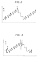
- Figure 2 is a graph showing the variation with time (abscissa) of the extent to which the buffer is full (ordinate) in the prior art arrangement.
- the saw-tooth effect is due to the fact that an entire group must be present in the buffer in order for information to be recovered from it. When all the information has been recovered the entire group becomes free.
- the drive must maintain at least one group in the buffer at all times in order to provide a continuous flow of information out of the drive.
- the time at which reading is started is shown at R and the time at which reading is stopped and repositioning is started is shown as S.
- the net effect of this addition is that for each reposition, more information is transferred. This reduces the number of repositions the device has to perform, thus reducing mechanical wear and enhancing reliability.
- the graph of figure 3 illustrates the effect of this system with respect to the quantity of information in the buffer at any given time.
- control of these functions is effected by the micro-processor of Figure 1 under the control of the program in the ROM.
- the addressing unit is controlled to direct the head of the new data group to the appropriate position in the buffer ahead of the already-read tail. In this way the data is fed out from the buffer in the appropriate order.
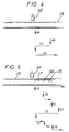
- Figure 4 there is shown a tape 13 running past a tape head 14 and there is illustrated a repositioning procedure in accordance with the prior art.
- the buffer is filled at 4A, when reading ceases and the tape drive is instructed to stop.
- the tape stops at 4B and 4C illustrates repositioning. Reading new data then commences (4D).
- Figure 5 shows an operation sequence in accordance with the invention.
- a buffer full signal is issued at 5A. Reading stops but the tape continues to run, no "stop" control signal being issued.
- a "buffer space available” signal issues and reading of the tail 15 of new data 16 begins.
- a tape stop signal is issued and reading stops.
- 5E represents repositioning to the restart position at the beginning of the new data.
- 5F shows restart and reading the head 17 of the new data.
- the tail 15 of the new data is skipped (not read) and at 5H reading recommences.
Landscapes
- Engineering & Computer Science (AREA)
- Theoretical Computer Science (AREA)
- Signal Processing (AREA)
- Human Computer Interaction (AREA)
- Physics & Mathematics (AREA)
- General Engineering & Computer Science (AREA)
- General Physics & Mathematics (AREA)
- Signal Processing For Digital Recording And Reproducing (AREA)
- Paper (AREA)
- Paints Or Removers (AREA)
- Addition Polymer Or Copolymer, Post-Treatments, Or Chemical Modifications (AREA)
Claims (6)
- Ein Bandlesegerät für digitale Daten zum Lesen von Daten und zum Liefern der Daten zu einer Vorrichtung (11), wobei das Gerät folgende Merkmale enthält: eine Lesekopfanordnung (3), eine Bandmotorvorrichtung, um das Band an der Lesekopfanordnung vorbei zu bewegen; einen elektronischen Puffer (10), der von Daten gefüllt wird, während sie vom Band gelesen werden und der von Daten geleert wird, während sie der Vorrichtung zugeführt werden; und eine Bandsteuervorrichtung (4,5,6), die auf den Datenpegel im Puffer anspricht, um das Band anzuhalten und das Band bezüglich der Lesekopfanordnung umzupositionieren, wobei die Bandsteuervorrichtung:
(a) auf ein Puffervollsignal vom Puffer anspricht, um die Neustartposition festzulegen, an die das Band als nächstes umpositioniert werden muß, wobei diese Bandposition dem Anfang der neuen Daten entspricht, die als nächstes dem Puffer zugeführt werden sollen;
dadurch gekennzeichnet, daß die Bandsteuervorrichtung:(b) wirksam ist, um zu ermöglichen, daß das Band nach Empfang eines Puffervollsignals weiterläuft;(c) auf ein Pufferplatz-Verfügbar-Signal vom Puffer anspricht, um mit dem Lesen von Daten von der gegenwärtigen Bandposition in den Puffer zu beginnen, wobei diese Daten der Schwanz der neuen Daten sind;(d) wirksam ist, um das Band am Ende des Schwanzes anzuhalten und das Band an die Neustartposition umzupositionieren;(e) wirksam ist, um danach den Kopf der neuen Daten einzulesen und in den Puffer zu plazieren; und(f) wirksam ist, um den bereits gelesenen Schwanz der neuen Daten zu entfernen. - Ein digitales Bandlesegerät nach Anspruch 1, bei dem die Daten in diskreten Gruppen auf dem Band aufgezeichnet sind, und die neuen Daten eine vollständige Gruppe sind.
- Ein digitales Bandlesegerät nach Anspruch 1, bei dem die Daten im digitalen Datenspeicher-Format (DDS-Format) auf dem Band aufgezeichnet sind.
- Ein Verfahren zum Lesen von Daten von einem Band und zum Liefern der Daten an eine Vorrichtung (11), unter Verwendung eines Bandlesegerätes für digitale Daten mit einer Lesekopfanordnung (3), einer Bandmotorvorrichtung, um das Band an der Lesekopfanordnung vorbei zu bewegen, einem elektronischen Puffer (10), der von Daten gefüllt wird, während sie vom Band gelesen werden und der von Daten geleert wird, während sie der Vorrichtung zugeführt werden, und einer Bandsteuervorrichtung (4, 5, 6), die auf den Datenpegel im Puffer anspricht, um das Band anzuhalten und das Band bezüglich der Lesekopfanordnung umzupositionieren, wobei das Verfahren folgende Schritte aufweist:(a) Lesen von Daten von dem Band in den Puffer;(b) Ansprechen auf ein Puffervollsignal von dem Puffer, um die Neustartposition zu bestimmen, an die das Band als nächstes umpositioniert werden muß, wobei diese Bandposition dem Anfang neuer Daten, die als nächstes dem Puffer zugeführt werden sollen, entspricht;gekennzeichnet durch folgende Schritte:(c) Ermöglichen, daß das Band nach dem Empfang des Puffervollsignals weiterläuft;(d) Ansprechen auf ein Pufferplatz-Verfügbar-Signal von dem Puffer, um das Lesen der Daten von der gegenwärtigen Bandposition in den Puffer zu beginnen, wobei diese Daten der Schwanz der neuen Daten sind;(e) Anhalten des Bandes am Ende des Schwanzes und Umpositionieren des Bandes an die Neustartposition;(f) Lesen des Kopfes der neuen Daten und Plazieren derselben in den Puffer; und(g) Entfernen des bereits gelesenen Schwanzes der neuen Daten.
- Ein Verfahren nach Anspruch 4, bei dem die Daten in diskreten Gruppen auf das Band aufgezeichnet sind und die neuen Daten eine vollständige Gruppe sind.
- Ein Verfahren nach Anspruch 4, bei dem die Daten im digitalen Datenspeicher-Format (DDS-Format) auf dem Band aufgezeichnet werden.
Priority Applications (5)
| Application Number | Priority Date | Filing Date | Title |
|---|---|---|---|
| EP90308143A EP0468112B1 (de) | 1990-07-25 | 1990-07-25 | Einrichtung zum Auslesen digitaler Daten von einem Band |
| DE69022229T DE69022229T2 (de) | 1990-07-25 | 1990-07-25 | Einrichtung zum Auslesen digitaler Daten von einem Band. |
| US07/838,409 US5377056A (en) | 1990-07-25 | 1991-07-05 | Digital data tape reading device |
| PCT/GB1991/001106 WO1992002016A1 (en) | 1990-07-25 | 1991-07-05 | Digital data tape reading device |
| JP03512025A JP3037417B2 (ja) | 1990-07-25 | 1991-07-05 | デジタル・データ・テープ読み取り装置 |
Applications Claiming Priority (1)
| Application Number | Priority Date | Filing Date | Title |
|---|---|---|---|
| EP90308143A EP0468112B1 (de) | 1990-07-25 | 1990-07-25 | Einrichtung zum Auslesen digitaler Daten von einem Band |
Publications (2)
| Publication Number | Publication Date |
|---|---|
| EP0468112A1 EP0468112A1 (de) | 1992-01-29 |
| EP0468112B1 true EP0468112B1 (de) | 1995-09-06 |
Family
ID=8205502
Family Applications (1)
| Application Number | Title | Priority Date | Filing Date |
|---|---|---|---|
| EP90308143A Expired - Lifetime EP0468112B1 (de) | 1990-07-25 | 1990-07-25 | Einrichtung zum Auslesen digitaler Daten von einem Band |
Country Status (5)
| Country | Link |
|---|---|
| US (1) | US5377056A (de) |
| EP (1) | EP0468112B1 (de) |
| JP (1) | JP3037417B2 (de) |
| DE (1) | DE69022229T2 (de) |
| WO (1) | WO1992002016A1 (de) |
Families Citing this family (5)
| Publication number | Priority date | Publication date | Assignee | Title |
|---|---|---|---|---|
| US6112261A (en) * | 1998-05-04 | 2000-08-29 | Hewlett-Packard Company | Data transferring system reading and temporarily storing a record until a length of the record is different from a defined record length parameter value |
| US6775087B2 (en) * | 2001-06-18 | 2004-08-10 | Sony Corporation | Method and apparatus to read past EOD marker |
| US6804075B1 (en) | 2002-03-01 | 2004-10-12 | Sony Corporation | Logical expiration of media having embedded non-volatile memory |
| US7190544B2 (en) * | 2004-11-10 | 2007-03-13 | Certance Llc | System and method for tape drive under run control |
| US7154695B2 (en) * | 2004-11-10 | 2006-12-26 | Certance, Llc | System and method for controlling the speed of a tape drive |
Family Cites Families (4)
| Publication number | Priority date | Publication date | Assignee | Title |
|---|---|---|---|---|
| US4821129A (en) * | 1986-11-21 | 1989-04-11 | Hewlett-Packard Company | Tape positioning using reverse boundary capture: tape drive system and method |
| US4891784A (en) * | 1988-01-08 | 1990-01-02 | Hewlett-Packard Company | High capacity tape drive transparently writes and reads large packets of blocked data between interblock gaps |
| EP0397778B1 (de) * | 1988-01-27 | 1995-12-13 | Storage Technology Corporation | Frühstartmodus-verfahren und -vorrichtung |
| JPH077573B2 (ja) * | 1988-10-07 | 1995-01-30 | シャープ株式会社 | 記録および再生方法 |
-
1990
- 1990-07-25 EP EP90308143A patent/EP0468112B1/de not_active Expired - Lifetime
- 1990-07-25 DE DE69022229T patent/DE69022229T2/de not_active Expired - Fee Related
-
1991
- 1991-07-05 US US07/838,409 patent/US5377056A/en not_active Expired - Lifetime
- 1991-07-05 WO PCT/GB1991/001106 patent/WO1992002016A1/en not_active Ceased
- 1991-07-05 JP JP03512025A patent/JP3037417B2/ja not_active Expired - Fee Related
Also Published As
| Publication number | Publication date |
|---|---|
| DE69022229D1 (de) | 1995-10-12 |
| DE69022229T2 (de) | 1996-02-29 |
| EP0468112A1 (de) | 1992-01-29 |
| US5377056A (en) | 1994-12-27 |
| WO1992002016A1 (en) | 1992-02-06 |
| JPH05503186A (ja) | 1993-05-27 |
| JP3037417B2 (ja) | 2000-04-24 |
Similar Documents
| Publication | Publication Date | Title |
|---|---|---|
| US6459540B1 (en) | Variable speed recording method and apparatus for a magnetic tape drive | |
| KR920008147B1 (ko) | 데이타 저장 및 검색 방법 | |
| US5442638A (en) | Apparatus and method for recording over defects in storage media | |
| CN1290079C (zh) | 一种磁带驱动器和向其写入数据的方法 | |
| US5953177A (en) | Write splicing for helical scan recorder | |
| US4492991A (en) | Method and apparatus for controlling the stepping feed of an information medium | |
| EP0468112B1 (de) | Einrichtung zum Auslesen digitaler Daten von einem Band | |
| EP0096456A2 (de) | Kapstanloses Magnetbandlaufwerk mit einem elektronischen Äquivalent zur Bandlänge | |
| US5258853A (en) | Facsimile apparatus having image memory device | |
| US3986208A (en) | Data recording with high speed search capability | |
| US4665443A (en) | Signal recording and reproducing apparatus | |
| US4814904A (en) | Method of controlling erasing following format writing in a magnetic disc apparatus | |
| CN102714047A (zh) | 控制数据写入的装置及方法 | |
| US4078258A (en) | System for arranging and sharing shift register memory | |
| US6580577B1 (en) | Magnetic tape apparatus with forced magnetic tape cleaning process | |
| US4084258A (en) | Apparatus for performing multiple operations in a shift register memory | |
| US4570189A (en) | High density digital data recording system | |
| EP0279885B1 (de) | Video-Signalwiedergabegerät | |
| US5363253A (en) | Tape drive fast seek to end-of-track | |
| US4991036A (en) | Moving data storage media mode/direction change optimization | |
| JPH05307444A (ja) | ストリーマ式磁気テープ装置 | |
| US5308961A (en) | Optical-card reader | |
| JP2002184117A (ja) | 光ディスク再生装置 | |
| JPH07302452A (ja) | 磁気テープ処理装置 | |
| JPH03183069A (ja) | 光磁気ディスクデータ転送方法 |
Legal Events
| Date | Code | Title | Description |
|---|---|---|---|
| PUAI | Public reference made under article 153(3) epc to a published international application that has entered the european phase |
Free format text: ORIGINAL CODE: 0009012 |
|
| AK | Designated contracting states |
Kind code of ref document: A1 Designated state(s): DE FR GB NL |
|
| 17P | Request for examination filed |
Effective date: 19920711 |
|
| 17Q | First examination report despatched |
Effective date: 19941213 |
|
| GRAA | (expected) grant |
Free format text: ORIGINAL CODE: 0009210 |
|
| AK | Designated contracting states |
Kind code of ref document: B1 Designated state(s): DE FR GB NL |
|
| REF | Corresponds to: |
Ref document number: 69022229 Country of ref document: DE Date of ref document: 19951012 |
|
| ET | Fr: translation filed | ||
| PLBE | No opposition filed within time limit |
Free format text: ORIGINAL CODE: 0009261 |
|
| STAA | Information on the status of an ep patent application or granted ep patent |
Free format text: STATUS: NO OPPOSITION FILED WITHIN TIME LIMIT |
|
| 26N | No opposition filed | ||
| REG | Reference to a national code |
Ref country code: GB Ref legal event code: IF02 |
|
| PGFP | Annual fee paid to national office [announced via postgrant information from national office to epo] |
Ref country code: DE Payment date: 20050831 Year of fee payment: 16 |
|
| PG25 | Lapsed in a contracting state [announced via postgrant information from national office to epo] |
Ref country code: DE Free format text: LAPSE BECAUSE OF NON-PAYMENT OF DUE FEES Effective date: 20070201 |
|
| PGFP | Annual fee paid to national office [announced via postgrant information from national office to epo] |
Ref country code: GB Payment date: 20070727 Year of fee payment: 18 |
|
| PGFP | Annual fee paid to national office [announced via postgrant information from national office to epo] |
Ref country code: FR Payment date: 20070717 Year of fee payment: 18 |
|
| GBPC | Gb: european patent ceased through non-payment of renewal fee |
Effective date: 20080725 |
|
| REG | Reference to a national code |
Ref country code: FR Ref legal event code: ST Effective date: 20090331 |
|
| PG25 | Lapsed in a contracting state [announced via postgrant information from national office to epo] |
Ref country code: GB Free format text: LAPSE BECAUSE OF NON-PAYMENT OF DUE FEES Effective date: 20080725 |
|
| PG25 | Lapsed in a contracting state [announced via postgrant information from national office to epo] |
Ref country code: FR Free format text: LAPSE BECAUSE OF NON-PAYMENT OF DUE FEES Effective date: 20080731 |
|
| PGFP | Annual fee paid to national office [announced via postgrant information from national office to epo] |
Ref country code: NL Payment date: 20090724 Year of fee payment: 20 |
|
| REG | Reference to a national code |
Ref country code: NL Ref legal event code: V4 Effective date: 20100725 |
|
| PG25 | Lapsed in a contracting state [announced via postgrant information from national office to epo] |
Ref country code: NL Free format text: LAPSE BECAUSE OF EXPIRATION OF PROTECTION Effective date: 20100725 |