EP0467643A2 - Lastmessgerät - Google Patents
Lastmessgerät Download PDFInfo
- Publication number
- EP0467643A2 EP0467643A2 EP91306437A EP91306437A EP0467643A2 EP 0467643 A2 EP0467643 A2 EP 0467643A2 EP 91306437 A EP91306437 A EP 91306437A EP 91306437 A EP91306437 A EP 91306437A EP 0467643 A2 EP0467643 A2 EP 0467643A2
- Authority
- EP
- European Patent Office
- Prior art keywords
- links
- measuring device
- load
- load measuring
- sensing means
- Prior art date
- Legal status (The legal status is an assumption and is not a legal conclusion. Google has not performed a legal analysis and makes no representation as to the accuracy of the status listed.)
- Granted
Links
- 230000001419 dependent effect Effects 0.000 claims abstract description 8
- 238000012545 processing Methods 0.000 claims abstract description 5
- 238000000034 method Methods 0.000 claims abstract description 4
- 238000011088 calibration curve Methods 0.000 claims description 3
- 239000011888 foil Substances 0.000 description 4
- 230000004044 response Effects 0.000 description 4
- 238000005259 measurement Methods 0.000 description 2
- 101100070120 Xenopus laevis has-rs gene Proteins 0.000 description 1
- 230000003321 amplification Effects 0.000 description 1
- 238000013459 approach Methods 0.000 description 1
- 238000010276 construction Methods 0.000 description 1
- 238000010586 diagram Methods 0.000 description 1
- 238000011835 investigation Methods 0.000 description 1
- 230000007257 malfunction Effects 0.000 description 1
- 238000003199 nucleic acid amplification method Methods 0.000 description 1
- 239000004033 plastic Substances 0.000 description 1
- 229920003023 plastic Polymers 0.000 description 1
- 238000012360 testing method Methods 0.000 description 1
- 239000002023 wood Substances 0.000 description 1
Images
Classifications
-
- G—PHYSICS
- G01—MEASURING; TESTING
- G01L—MEASURING FORCE, STRESS, TORQUE, WORK, MECHANICAL POWER, MECHANICAL EFFICIENCY, OR FLUID PRESSURE
- G01L5/00—Apparatus for, or methods of, measuring force, work, mechanical power, or torque, specially adapted for specific purposes
- G01L5/04—Apparatus for, or methods of, measuring force, work, mechanical power, or torque, specially adapted for specific purposes for measuring tension in flexible members, e.g. ropes, cables, wires, threads, belts or bands
- G01L5/047—Specific indicating or recording arrangements, e.g. for remote indication, for indicating overload or underload
-
- G—PHYSICS
- G01—MEASURING; TESTING
- G01G—WEIGHING
- G01G19/00—Weighing apparatus or methods adapted for special purposes not provided for in the preceding groups
- G01G19/14—Weighing apparatus or methods adapted for special purposes not provided for in the preceding groups for weighing suspended loads
- G01G19/18—Weighing apparatus or methods adapted for special purposes not provided for in the preceding groups for weighing suspended loads having electrical weight-sensitive devices
-
- G—PHYSICS
- G01—MEASURING; TESTING
- G01L—MEASURING FORCE, STRESS, TORQUE, WORK, MECHANICAL POWER, MECHANICAL EFFICIENCY, OR FLUID PRESSURE
- G01L5/00—Apparatus for, or methods of, measuring force, work, mechanical power, or torque, specially adapted for specific purposes
- G01L5/04—Apparatus for, or methods of, measuring force, work, mechanical power, or torque, specially adapted for specific purposes for measuring tension in flexible members, e.g. ropes, cables, wires, threads, belts or bands
- G01L5/10—Apparatus for, or methods of, measuring force, work, mechanical power, or torque, specially adapted for specific purposes for measuring tension in flexible members, e.g. ropes, cables, wires, threads, belts or bands using electrical means
- G01L5/102—Apparatus for, or methods of, measuring force, work, mechanical power, or torque, specially adapted for specific purposes for measuring tension in flexible members, e.g. ropes, cables, wires, threads, belts or bands using electrical means using sensors located at a non-interrupted part of the flexible member
Definitions
- the invention relates to a load measuring device, and in particular to a load measuring device having a plurality of links arranged in a chain, and sensing means arranged on a link for sensing the strain in the link.
- load measuring devices are utilised in many situations where it is desired to monitor or measure loads, for example in construction work where heavy objects are lifted by cranes, or in situations where objects are being towed or dragged using cables or chains, such as the towing of barges by tugs, or in the logging industry where logs are towed behind traction vehicles.
- a basic load measuring device consists of a mechanical link provided with electronic circuitry including a sensor which responds to the elastic distortion in the mechanical link.
- sensors for detecting elastic distortion are presently available, including for example foil strain gauges which alter in electrical resistance in response to the strain on the link.
- a further sensor comprises a simple coil wound around a side of a link, the variations in the magnetic properties of the link in response to applied stress causing a change in the current flow in the wire which is indicative of the stress level.
- the present invention seeks to provide a measuring device having an extended load measuring range, for a given required accuracy, or an increased accuracy at a given load.
- a load measuring device comprising a plurality of links arranged in a chain, to which a load to be measured is applied, respective sensing means disposed on two or more links for detecting the strain in the links and giving output signals dependent on the strain in those links, and processing means to process the output signals and to compute a corrected signal indicative of the applied load.
- the utilisation of two or more sensing means provided on separate links provides separate output signals which can be manipulated to provide a single signal of increased accuracy.
- At least four links are provided, with sensing means disposed on four links.
- the sensing means comprise strain gauges.
- the processing means may include a microcomputer system, which is programmed to sum the signals from the sensing means disposed on separate links. By summing these signals a signal of increased signal/noise ratio is obtained which may be utilised to provide a corrected signal of increased accuracy indicative of the applied load, or, for a required accuracy, to effectively extend the lower limit of acceptable measurement of the device. For example, by providing four signals for summation the lower acceptable limit of measurement is extended to approximately 1/4 of the limit where only a single sensing means is utlised.
- the microcomputer system is programmed to sum only those signals from the sensing means of separate links which do not differ from each other by more than a predetermined amount. In this way, spurious signals which might be the result of component malfunctions can be disregarded in the signal summation.
- the microcomputer system is arranged to output a corrected signal which is linearly dependent on the applied load, by comparing the input signals with a calibration curve.
- a corrected signal which is linearly dependent on the applied load, by comparing the input signals with a calibration curve.
- an archival memory is connected to the microcomputer system which is arranged to record the loading history of the device.
- the device may include a radio transmitter for transmitting the corrected signal indicative of the applied load to a remote receiver at which the signal is received and the value of the applied load is displayed.
- a series of oval mechanical links 2 are arranged in a chain between larger-sized links 4 which facilitate attachment of the chain to an applied load.
- a number of the links 2 are provided with sensing means in the form of strain gauges G mounted on the links so as to undergo extension with the links on loading.
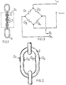
- Figure 1 shows strain gauges provided on four links 2.
- the strain gauges G are foil strain gauges which are mounted on the links and which consist of plastics foils provided with a plurality of fine wires. On the extension of the link on loading, the gauges change their resistance according to the extension, and hence to the applied load.
- foil strain gauges are commercially available, as for example, No. RS 632-124.
- any other sensing means which produce an output indicative of the elastic distortion in a link may be used.
- a coil wound around a side of a link may be used.
- Each mechanical link 2 may be provided with from one to four strain gauges.
- Figure 2 shows four strain gauges G1, G2, G3, G4 arranged on a link 2. These can be mounted on the links 2 in any position which experiences an extension with loading of the chain. It is found that a particularly effective response is produced if the strain gauges G1, G2, G3, G4 are positioned on opposing sides of a link as shown in Figure 2. Where four strain gauges G1, G2, G3, G4 are utilised, these are electrically connected in a bridge arrangement, as shown in Figure 3. A voltage, indicated by Vref - Ground is applied across the bridge, whilst the voltage at the arms of the bridge, S1, S2 are indicative of the strains experienced by the guages, and hence of the applied loads.
- gauges can be substituted by standard resistors in the bridge circuit; for example, the link could include only two strain gauges, G1 and G2 with G3 and G4 substituted by standard resistors. It is to be appreciated that the bridge circuit merely provides a convenient arrangement of strain gauges, and that any arrangement which provides an output signal indicative of applied load can be utlised.
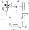
- the outputs from the sensing means on each link 2 indicated by LC, RC, XC, YC in Figure 4 are connected to a first multiplexor 10 functioning as a switching element to selectively control the flow of signals from the various sensing means.
- the operation of the first multiplexor 10 is controlled by a microcomputer system 12.
- Signals from the first multiplexor 10 are passed to a second multiplexor 14 via an instrumentation amplifier 16 which provides signal amplification.
- a typical amplifier which can be used has RS No. 308-815.
- the second multiplexor 14 is additionally connected to a number of reference voltages required in order that the system provide internal self-checks.
- Figure 3 shows V batt, representing the battery voltage, which is monitored to ensure the battery voltage is sufficient for correct functioning of the electronic components.
- V ref and Ground represent voltages supplied at the bridge as is shown in Figure 3.
- V Cal represents a preselected voltage equivalent to a known load which may be utilised in providing checks on the correct functioning of the electronic components.
- This second multiplexor 14 is also controlled by the microcomputer system 12.
- a commerically available multiplexor which can be used for both the first and second multiplexors 10 and 14 is RS 639-850.
- Signals from the second multiplexor 14 are digitised in the analogue to digital convertor 15, before input to the microcomputer system 12.
- a typical analogue/digital convertor which may be used is RS No. 647-435.
- the microcomputer system 12 is arranged to process the signals from the various sensing means to yield an accurate output which is linearly dependent on the true load on the cell.
- the signals from the various sensing means are summed to provide a single signal S sum of increased signal/noise ratio.
- This signal S sum is then effectively compared with a predetermined calibration curve to provide a corrected output which is linearly dependent on the applied load.
- the summation of signals increases the reliability of the computed load, at a given load, or effectively increases the lower limit of use of the device for a given reliability.
- sensing means associated with a number of different links 2 each independantly providing signals indicative of the applied load
- a comparison can be made between the signals from the different sensing means.
- An apparent spurious signal which varies from the signals given by other sensing means by more than a preselected amount (which would indicate faulty equipment) can be rejected in the signal summation and hence in the load computation.
- the microcomputer 12 can be programmed to sum signals from say only two sensing means when the device is being operated with loads well above its lower limit of accuracy, and when smaller loads are used, which approach the device's lower limit of accuracy, to include signals from other sensing means in the summation.
- Calibration of the device can be achieved by using known loads to compute an applied load versus signal curve, and applying a polynomial curve to extrapolate between points. A theoretical linear response is also computed so that for any input signal a corrected output signal corresponding to that load is computed, with the corrected output signal being directly proportional to the applied load.
- Output signals from the microcomputer system 12 are sent via a signal data interface 18 (for example RS No. 655-290) where the computer output is transferred into a transmissible format, to a radio transmitter 20 at which the output data is transmitted to a remote receiver.
- a receiver module remote from the transmitter receives the transmitted data and is arranged to provide a real time display of the applied load on an LCD or LED display.
- An example of a radio transmitter which may be utilised is the TT405 manufactured by Wood and Douglas. Where remote sensing of the load is not required the radio transmitter/receiver link can be replaced by a simple wire link.
- Other computers can be connected to the microcomputer system 12 via the serial data interface 18, for example, for carrying out tests on the device.
- microcomputer system to carry out the signal control and load computation
- an appropriately arranged microprocessor can alternatively be used.
- a further feature which may be incorporated into the device is an additional memory in the form of an archival memory 22.
- This is connected to the microcomputer system 12, and is used for storing the service history of the device, by for example, storing a complete record of loading against time, or recording loading only above a preselected load threshold, or alternatively, recording loading against time only on unloading of the cell. Such a record is useful particularly in accident or failure investigation where precise loading details at the time of failure are very important.
- a typical memory which may be used is RS No.657 202 memory card.
- the entire device including the electronic components and links 2 provided with the sensing means are contained within a housing 24, indicated by the dotted lines on Figure 1.
- the larger-sized links 4 are outside the housing 24.
- the device thus forms a stand-alone sensing and transmitter module for interposition into a loaded line.
Landscapes
- Physics & Mathematics (AREA)
- General Physics & Mathematics (AREA)
- Chemical & Material Sciences (AREA)
- Analytical Chemistry (AREA)
- Measurement Of Force In General (AREA)
- Measuring Pulse, Heart Rate, Blood Pressure Or Blood Flow (AREA)
- Forklifts And Lifting Vehicles (AREA)
- Testing Electric Properties And Detecting Electric Faults (AREA)
- Force Measurement Appropriate To Specific Purposes (AREA)
- Transition And Organic Metals Composition Catalysts For Addition Polymerization (AREA)
- Steroid Compounds (AREA)
Applications Claiming Priority (2)
| Application Number | Priority Date | Filing Date | Title |
|---|---|---|---|
| GB9015620A GB2246199B (en) | 1990-07-16 | 1990-07-16 | Load measuring device |
| GB9015620 | 1990-07-16 |
Publications (3)
| Publication Number | Publication Date |
|---|---|
| EP0467643A2 true EP0467643A2 (de) | 1992-01-22 |
| EP0467643A3 EP0467643A3 (en) | 1992-10-14 |
| EP0467643B1 EP0467643B1 (de) | 1997-12-03 |
Family
ID=10679172
Family Applications (1)
| Application Number | Title | Priority Date | Filing Date |
|---|---|---|---|
| EP91306437A Expired - Lifetime EP0467643B1 (de) | 1990-07-16 | 1991-07-16 | Lastmessgerät |
Country Status (7)
| Country | Link |
|---|---|
| US (1) | US5224388A (de) |
| EP (1) | EP0467643B1 (de) |
| AT (1) | ATE160869T1 (de) |
| AU (1) | AU646058B2 (de) |
| CA (1) | CA2047109C (de) |
| DE (1) | DE69128311T2 (de) |
| GB (1) | GB2246199B (de) |
Cited By (6)
| Publication number | Priority date | Publication date | Assignee | Title |
|---|---|---|---|---|
| NL1001524C2 (nl) * | 1995-10-30 | 1997-05-02 | Doornes Transmissie Bv | Meetsysteem. |
| WO2002068310A3 (en) * | 2001-02-23 | 2002-12-19 | Renold Plc | A load monitoring and inventory management system for use with a load conveyor |
| US6774320B2 (en) * | 2001-11-30 | 2004-08-10 | Gerald S. Simons | Standard attachment fittings for wire rope and chain enhanced to also perform load weighing functions |
| EP2017594A3 (de) * | 2007-07-10 | 2009-03-25 | Mytrak Health System Inc. | Kraftmesssystem für ein gespanntes flexibles Element |
| US7634949B2 (en) | 2005-07-23 | 2009-12-22 | Renold Plc | Transmission chain monitoring system |
| ES2338857A1 (es) * | 2010-01-21 | 2010-05-12 | Miceletc, S.L. | Sensor inalambrico para el control de la tension de cables de traccion. |
Families Citing this family (25)
| Publication number | Priority date | Publication date | Assignee | Title |
|---|---|---|---|---|
| AU655861B2 (en) * | 1992-01-17 | 1995-01-12 | Grant David Hodson | A load monitor |
| GB2299847B (en) * | 1993-02-03 | 1997-06-04 | Hugh Michael Oppen Pratt | Load insulator |
| US5606516A (en) * | 1995-08-07 | 1997-02-25 | Fairbanks Scales Inc. | Digitally compensated hydraulic scale system |
| US20030197094A1 (en) * | 2001-12-07 | 2003-10-23 | Daniel Preston | Load measuring device |
| US7316169B2 (en) * | 2002-06-14 | 2008-01-08 | Peerless Chain Company | Load bearing device including overload indicator |
| US7032466B2 (en) | 2002-06-14 | 2006-04-25 | Peerless Chain | Load bearing device including overboard indicator |
| US20060008341A1 (en) * | 2002-07-10 | 2006-01-12 | Mazzella Lifting Technologies | Method for collecting, distributing, and viewing inspection reports for lifting devices |
| GB2411776B (en) * | 2004-03-03 | 2007-12-12 | Hugh Michael Oppen Pratt | Tag line insulator |
| JP2007057377A (ja) * | 2005-08-24 | 2007-03-08 | Tsubakimoto Chain Co | チェーン張力測定方法 |
| US9156167B2 (en) * | 2007-05-15 | 2015-10-13 | Trimble Navigation Limited | Determining an autonomous position of a point of interest on a lifting device |
| US8103438B2 (en) | 2007-09-26 | 2012-01-24 | Trimble Navigation Limited | Method and system for automatically directing traffic on a site |
| US8144000B2 (en) * | 2007-09-26 | 2012-03-27 | Trimble Navigation Limited | Collision avoidance |
| US8081108B2 (en) * | 2008-01-07 | 2011-12-20 | Trimble Navigation Limited | Autonomous projection of global navigation satellite orbits |
| US8054181B2 (en) * | 2008-04-09 | 2011-11-08 | Trimble Navigation Limited | Terrestial-signal based exclusion zone compliance |
| US8224518B2 (en) * | 2008-08-18 | 2012-07-17 | Trimble Navigation Limited | Automated recordation of crane inspection activity |
| US8514058B2 (en) * | 2008-08-18 | 2013-08-20 | Trimble Navigation Limited | Construction equipment component location tracking |
| US20100070179A1 (en) * | 2008-09-17 | 2010-03-18 | Cameron John F | Providing an autonomous position of a point of interest to a lifting device to avoid collision |
| US8631636B2 (en) * | 2011-09-19 | 2014-01-21 | Tecsis Delta Metrics | Shackle assembly |
| CA2851129C (en) * | 2011-10-30 | 2017-10-31 | Paskal Technologies Agriculture Cooperative Society Ltd. | Self-learning of plant growth strategy in a greenhouse |
| US9576475B2 (en) | 2013-09-10 | 2017-02-21 | Southwire Company, Llc | Wireless-enabled tension meter |
| USD723406S1 (en) | 2013-09-23 | 2015-03-03 | Southwire Company, Llc | Tension meter |
| USD724457S1 (en) | 2013-09-23 | 2015-03-17 | Southwire Company, Llc | Tension meter |
| PL2881720T3 (pl) * | 2013-12-09 | 2019-07-31 | Caterpillar Global Mining Europe Gmbh | Jednostka do pomiaru siły i system do pomiaru sił na łańcuchach |
| JP7098403B2 (ja) * | 2018-04-25 | 2022-07-11 | 日本車輌製造株式会社 | 荷吊り作業における安全管理システム |
| JP7320487B2 (ja) * | 2020-12-24 | 2023-08-03 | ロジスティード株式会社 | 張力検出装置及び張力調整装置 |
Family Cites Families (14)
| Publication number | Priority date | Publication date | Assignee | Title |
|---|---|---|---|---|
| US842339A (en) * | 1906-04-04 | 1907-01-29 | Marconi Wireless Telegraph Co | Apparatus for electrically indicating weight. |
| US2550588A (en) * | 1947-05-27 | 1951-04-24 | North American Aviation Inc | Ring dynamometer |
| GB903941A (en) * | 1959-07-14 | 1962-08-22 | Vyzk A Zkusebni Letecky Ustav | Improvements in or relating to strain measuring devices |
| GB897116A (en) * | 1960-09-28 | 1962-05-23 | Campbell Chain Co | Sling member |
| US3722268A (en) * | 1971-03-04 | 1973-03-27 | Global Marine Inc | Load indicator for mooring line |
| GB1569150A (en) * | 1976-10-27 | 1980-06-11 | Cil Electronics Ltd | Strain gauge arrangements |
| GB2041549B (en) * | 1979-02-02 | 1983-08-17 | Post Office | Measuring tension in chains |
| US4283942A (en) * | 1979-05-25 | 1981-08-18 | Fishfader Stanley S | Load measuring device |
| EP0130298A3 (de) * | 1983-07-01 | 1986-01-08 | MANNESMANN Aktiengesellschaft | Lastmesseinrichtung für Hebezeuge |
| GB8333187D0 (en) * | 1983-12-13 | 1984-01-18 | Farley F J M | Load recording |
| US4566339A (en) * | 1983-12-23 | 1986-01-28 | Southern Systems, Inc. | Chain pull monitor system |
| DE3531118A1 (de) * | 1985-08-30 | 1987-03-12 | Micro Epsilon Messtechnik | Verfahren zur fehlerkompensation fuer messwertaufnehmer mit nicht linearen kennlinien, sowie anordnung zur durchfuehrung des verfahrens |
| GB2205411B (en) * | 1987-06-01 | 1991-09-11 | Hugh Michael O Pratt | Load cell |
| US4803886A (en) * | 1988-01-14 | 1989-02-14 | Larry May | Chain pull analyzer system |
-
1990
- 1990-07-16 GB GB9015620A patent/GB2246199B/en not_active Expired - Fee Related
-
1991
- 1991-07-15 US US07/730,158 patent/US5224388A/en not_active Expired - Fee Related
- 1991-07-16 DE DE69128311T patent/DE69128311T2/de not_active Expired - Fee Related
- 1991-07-16 AT AT91306437T patent/ATE160869T1/de not_active IP Right Cessation
- 1991-07-16 EP EP91306437A patent/EP0467643B1/de not_active Expired - Lifetime
- 1991-07-16 CA CA002047109A patent/CA2047109C/en not_active Expired - Fee Related
- 1991-07-16 AU AU80488/91A patent/AU646058B2/en not_active Ceased
Cited By (9)
| Publication number | Priority date | Publication date | Assignee | Title |
|---|---|---|---|---|
| NL1001524C2 (nl) * | 1995-10-30 | 1997-05-02 | Doornes Transmissie Bv | Meetsysteem. |
| US5898298A (en) * | 1995-10-30 | 1999-04-27 | Van Doorne's Transmissie B.V. | Inductor/capacitor-based measuring system for a moving body |
| WO2002068310A3 (en) * | 2001-02-23 | 2002-12-19 | Renold Plc | A load monitoring and inventory management system for use with a load conveyor |
| US6774320B2 (en) * | 2001-11-30 | 2004-08-10 | Gerald S. Simons | Standard attachment fittings for wire rope and chain enhanced to also perform load weighing functions |
| US7634949B2 (en) | 2005-07-23 | 2009-12-22 | Renold Plc | Transmission chain monitoring system |
| US7886613B2 (en) | 2005-07-23 | 2011-02-15 | Renold Plc | Transmission chain monitoring system |
| EP2017594A3 (de) * | 2007-07-10 | 2009-03-25 | Mytrak Health System Inc. | Kraftmesssystem für ein gespanntes flexibles Element |
| ES2338857A1 (es) * | 2010-01-21 | 2010-05-12 | Miceletc, S.L. | Sensor inalambrico para el control de la tension de cables de traccion. |
| ES2338857B1 (es) * | 2010-01-21 | 2011-02-02 | Micelect, S.L. | Sensor inalambrico para el control de la tension de cables de traccion. |
Also Published As
| Publication number | Publication date |
|---|---|
| EP0467643A3 (en) | 1992-10-14 |
| GB2246199A (en) | 1992-01-22 |
| EP0467643B1 (de) | 1997-12-03 |
| AU646058B2 (en) | 1994-02-03 |
| GB9015620D0 (en) | 1990-09-05 |
| DE69128311D1 (de) | 1998-01-15 |
| DE69128311T2 (de) | 1998-06-10 |
| US5224388A (en) | 1993-07-06 |
| AU8048891A (en) | 1992-01-16 |
| GB2246199B (en) | 1994-02-09 |
| CA2047109C (en) | 1997-10-07 |
| ATE160869T1 (de) | 1997-12-15 |
| CA2047109A1 (en) | 1992-01-17 |
Similar Documents
| Publication | Publication Date | Title |
|---|---|---|
| EP0467643B1 (de) | Lastmessgerät | |
| US4020911A (en) | Load cell scale | |
| EP0670479B1 (de) | Kraftmessdose mit modularen Eichkomponenten | |
| US7538281B2 (en) | Load cells for use in high precision load measuring system | |
| US5220971A (en) | Shear beam, single-point load cell | |
| US4977783A (en) | Load monitor | |
| US6236215B1 (en) | Cell voltage detection circuit, and method of detecting cell voltage | |
| EP0132930A1 (de) | Dehnungsmessstreifenanordnungen | |
| CN112985571A (zh) | 数字称重传感器及其称重系统 | |
| EP0299806B1 (de) | Wägeapparat mit Dehnungsmessstreifen | |
| US5841077A (en) | Digital load cell assembly | |
| US4261195A (en) | Transducer bridge circuit arrangement and method | |
| SE464374B (sv) | Kraftmaetaranordning foer maetning av vertikalkraftkomponenten verkande paa ett kopplingsdon mellan ett dragfordon och ett slaepfordon | |
| US5016200A (en) | Weight determining apparatus utilizing acoustic wave elapsed time measurement and computer | |
| US4138882A (en) | Transducer bridge circuit arrangement | |
| JPH05322637A (ja) | トラックスケールの故障診断システム | |
| US20050011277A1 (en) | System and method for load sensing using piezoelectric effect | |
| CN114705356A (zh) | 一种电阻应变片式测力传感器的自校准方法 | |
| KR100375026B1 (ko) | 스트레인게이지를 응용한 변형검출기로 구조물의 물리량을 측정하는 검출장치 | |
| CN109443503B (zh) | 检测装置 | |
| JPH0514871U (ja) | 歪・温度センサの異常検出装置 | |
| CN220304712U (zh) | 具有偏载检测功能的轧制力数字测量仪 | |
| JPS62167432A (ja) | 材料試験機 | |
| US4449058A (en) | Load status monitoring apparatus | |
| DE3132267C2 (de) | Temperaturkompensationsanordnung an einer Wägezelle mit Dehnungsmeßstreifen |
Legal Events
| Date | Code | Title | Description |
|---|---|---|---|
| PUAI | Public reference made under article 153(3) epc to a published international application that has entered the european phase |
Free format text: ORIGINAL CODE: 0009012 |
|
| AK | Designated contracting states |
Kind code of ref document: A2 Designated state(s): AT BE DE DK ES FR IT NL SE |
|
| PUAL | Search report despatched |
Free format text: ORIGINAL CODE: 0009013 |
|
| AK | Designated contracting states |
Kind code of ref document: A3 Designated state(s): AT BE DE DK ES FR IT NL SE |
|
| 17P | Request for examination filed |
Effective date: 19930413 |
|
| 17Q | First examination report despatched |
Effective date: 19940420 |
|
| GRAG | Despatch of communication of intention to grant |
Free format text: ORIGINAL CODE: EPIDOS AGRA |
|
| GRAG | Despatch of communication of intention to grant |
Free format text: ORIGINAL CODE: EPIDOS AGRA |
|
| GRAH | Despatch of communication of intention to grant a patent |
Free format text: ORIGINAL CODE: EPIDOS IGRA |
|
| GRAH | Despatch of communication of intention to grant a patent |
Free format text: ORIGINAL CODE: EPIDOS IGRA |
|
| GRAA | (expected) grant |
Free format text: ORIGINAL CODE: 0009210 |
|
| AK | Designated contracting states |
Kind code of ref document: B1 Designated state(s): AT BE DE DK ES FR IT NL SE |
|
| PG25 | Lapsed in a contracting state [announced via postgrant information from national office to epo] |
Ref country code: AT Free format text: LAPSE BECAUSE OF FAILURE TO SUBMIT A TRANSLATION OF THE DESCRIPTION OR TO PAY THE FEE WITHIN THE PRESCRIBED TIME-LIMIT Effective date: 19971203 Ref country code: BE Free format text: LAPSE BECAUSE OF FAILURE TO SUBMIT A TRANSLATION OF THE DESCRIPTION OR TO PAY THE FEE WITHIN THE PRESCRIBED TIME-LIMIT Effective date: 19971203 Ref country code: FR Free format text: LAPSE BECAUSE OF FAILURE TO SUBMIT A TRANSLATION OF THE DESCRIPTION OR TO PAY THE FEE WITHIN THE PRESCRIBED TIME-LIMIT Effective date: 19971203 Ref country code: ES Free format text: THE PATENT HAS BEEN ANNULLED BY A DECISION OF A NATIONAL AUTHORITY Effective date: 19971203 Ref country code: DK Free format text: LAPSE BECAUSE OF NON-PAYMENT OF DUE FEES Effective date: 19971203 Ref country code: IT Free format text: LAPSE BECAUSE OF FAILURE TO SUBMIT A TRANSLATION OF THE DESCRIPTION OR TO PAY THE FEE WITHIN THE PRE;WARNING: LAPSES OF ITALIAN PATENTS WITH EFFECTIVE DATE BEFORE 2007 MAY HAVE OCCURRED AT ANY TIME BEFORE 2007. THE CORRECT EFFECTIVE DATE MAY BE DIFFERENT FROM THE ONE RECORDED.SCRIBED TIME-LIMIT Effective date: 19971203 |
|
| REF | Corresponds to: |
Ref document number: 160869 Country of ref document: AT Date of ref document: 19971215 Kind code of ref document: T |
|
| REF | Corresponds to: |
Ref document number: 69128311 Country of ref document: DE Date of ref document: 19980115 |
|
| PG25 | Lapsed in a contracting state [announced via postgrant information from national office to epo] |
Ref country code: SE Free format text: LAPSE BECAUSE OF FAILURE TO SUBMIT A TRANSLATION OF THE DESCRIPTION OR TO PAY THE FEE WITHIN THE PRESCRIBED TIME-LIMIT Effective date: 19980303 |
|
| EN | Fr: translation not filed | ||
| PLBE | No opposition filed within time limit |
Free format text: ORIGINAL CODE: 0009261 |
|
| STAA | Information on the status of an ep patent application or granted ep patent |
Free format text: STATUS: NO OPPOSITION FILED WITHIN TIME LIMIT |
|
| 26N | No opposition filed | ||
| PGFP | Annual fee paid to national office [announced via postgrant information from national office to epo] |
Ref country code: DE Payment date: 19990930 Year of fee payment: 9 |
|
| PGFP | Annual fee paid to national office [announced via postgrant information from national office to epo] |
Ref country code: NL Payment date: 20000731 Year of fee payment: 10 |
|
| PG25 | Lapsed in a contracting state [announced via postgrant information from national office to epo] |
Ref country code: DE Free format text: LAPSE BECAUSE OF NON-PAYMENT OF DUE FEES Effective date: 20010501 |
|
| PG25 | Lapsed in a contracting state [announced via postgrant information from national office to epo] |
Ref country code: NL Free format text: LAPSE BECAUSE OF NON-PAYMENT OF DUE FEES Effective date: 20020201 |
|
| NLV4 | Nl: lapsed or anulled due to non-payment of the annual fee |
Effective date: 20020201 |