EP0467386A2 - Emetteurs d'irrigation goutte à goutte - Google Patents
Emetteurs d'irrigation goutte à goutte Download PDFInfo
- Publication number
- EP0467386A2 EP0467386A2 EP91112110A EP91112110A EP0467386A2 EP 0467386 A2 EP0467386 A2 EP 0467386A2 EP 91112110 A EP91112110 A EP 91112110A EP 91112110 A EP91112110 A EP 91112110A EP 0467386 A2 EP0467386 A2 EP 0467386A2
- Authority
- EP
- European Patent Office
- Prior art keywords
- elastomeric member
- flow
- outlet
- housing
- control chamber
- Prior art date
- Legal status (The legal status is an assumption and is not a legal conclusion. Google has not performed a legal analysis and makes no representation as to the accuracy of the status listed.)
- Granted
Links
- 230000002262 irrigation Effects 0.000 title claims abstract description 20
- 238000003973 irrigation Methods 0.000 title claims abstract description 20
- 239000003638 chemical reducing agent Substances 0.000 claims abstract description 39
- 230000015572 biosynthetic process Effects 0.000 claims abstract description 8
- XLYOFNOQVPJJNP-UHFFFAOYSA-N water Substances O XLYOFNOQVPJJNP-UHFFFAOYSA-N 0.000 claims description 36
- 210000002445 nipple Anatomy 0.000 claims description 12
- 238000007599 discharging Methods 0.000 claims description 2
- 238000005192 partition Methods 0.000 description 16
- 238000010276 construction Methods 0.000 description 12
- 230000001965 increasing effect Effects 0.000 description 5
- 230000001105 regulatory effect Effects 0.000 description 5
- 230000003247 decreasing effect Effects 0.000 description 3
- 238000005755 formation reaction Methods 0.000 description 3
- 230000004048 modification Effects 0.000 description 3
- 238000012986 modification Methods 0.000 description 3
- 230000002093 peripheral effect Effects 0.000 description 2
- 241000196324 Embryophyta Species 0.000 description 1
- 239000011324 bead Substances 0.000 description 1
- 238000004049 embossing Methods 0.000 description 1
- 230000002708 enhancing effect Effects 0.000 description 1
- 239000003621 irrigation water Substances 0.000 description 1
- 230000000670 limiting effect Effects 0.000 description 1
- 238000004519 manufacturing process Methods 0.000 description 1
- 239000000463 material Substances 0.000 description 1
- 238000007789 sealing Methods 0.000 description 1
- 230000035945 sensitivity Effects 0.000 description 1
Images


Classifications
-
- A—HUMAN NECESSITIES
- A01—AGRICULTURE; FORESTRY; ANIMAL HUSBANDRY; HUNTING; TRAPPING; FISHING
- A01G—HORTICULTURE; CULTIVATION OF VEGETABLES, FLOWERS, RICE, FRUIT, VINES, HOPS OR SEAWEED; FORESTRY; WATERING
- A01G25/00—Watering gardens, fields, sports grounds or the like
- A01G25/02—Watering arrangements located above the soil which make use of perforated pipe-lines or pipe-lines with dispensing fittings, e.g. for drip irrigation
- A01G25/023—Dispensing fittings for drip irrigation, e.g. drippers
-
- Y—GENERAL TAGGING OF NEW TECHNOLOGICAL DEVELOPMENTS; GENERAL TAGGING OF CROSS-SECTIONAL TECHNOLOGIES SPANNING OVER SEVERAL SECTIONS OF THE IPC; TECHNICAL SUBJECTS COVERED BY FORMER USPC CROSS-REFERENCE ART COLLECTIONS [XRACs] AND DIGESTS
- Y02—TECHNOLOGIES OR APPLICATIONS FOR MITIGATION OR ADAPTATION AGAINST CLIMATE CHANGE
- Y02A—TECHNOLOGIES FOR ADAPTATION TO CLIMATE CHANGE
- Y02A40/00—Adaptation technologies in agriculture, forestry, livestock or agroalimentary production
- Y02A40/10—Adaptation technologies in agriculture, forestry, livestock or agroalimentary production in agriculture
- Y02A40/22—Improving land use; Improving water use or availability; Controlling erosion
Definitions
- the present invention relates to drip irrigation emitters and to drip irrigation lines of the type including a continuous tube having a plurality of emitters spaced longitudinally along its length.
- Drip irrigation lines of the foregoing type are gaining widespread use because of their efficiency in the delivery of irrigating water directly to the plant roots, and their substantial savings in the irrigation water required.
- Such drip irrigation lines generally comprise a tube having a plurality of discharge ports spaced along its length, and a flow-reducer emitters fixed to the tube at each of the discharge ports.
- each of the emitters includes a rigid plastic member and an elastomeric member fixed to the rigid plastic member and definining therewith a flow-reducing passageway communicating with its respective discharge port, which passageway is automatically enlarged or restricted by the deformation of the elastomeric member in response to flow.
- the elastomeric member in the conventional emitter, is usually in the form of a planar diaphragm, and the rigid plastic member is usually formed with embossments cooperable with the planar diaphragm to define the enlargeable/restrictable flow- reducing passageway regulating the flow to the discharge port.
- embossments cooperable with the planar diaphragm to define the enlargeable/restrictable flow- reducing passageway regulating the flow to the discharge port.
- An object of the present invention is to provide a drip irrigation emitter for a drip irrigation line of the foregoing type but modified to produce a number of important advantages as will be described more particularly below.
- a drip irrigation emitter comprising a housing including an inlet connectible to a source of pressurized water, an outlet for discharging the water from the housing, a flow-reducer passageway between the inlet and outlet for reducing the flow of water discharged through the outlet, and an elastomeric member fixed within the housing and defining, with an internal surface thereof, at least a part of the flow-reducer passageway which part is automatically enlarged or restricted by deformation of the elastomeric member in response to flow through the at least part of the flow reducer passageway; characterized in that the elastomeric member is embossed with an integrally formed relief formation on the surface thereof facing the internal surface of the housing to space same from the internal surface and to permit the enlargement or reduction of the at least part of the flow-reducer passageway upon the deformation of the elastomeric member in response to the flow.
- the drip irrigation line illustrated in Figs. 1-2d comprises a tube 2 having a plurality of discharge ports 3 spaced along its length, and a flow-reducer element, generally designated 4, fixed to the inner face of the tube at each of the discharge ports.
- Each of the flow-reducer elements 4 includes a rigid plastic body constituted of an outer rigid plastic section 5 and an inner rigid plastic section 6; and an elastomeric member 7 fixed within the inner rigid plastic section 6 to define a passageway leading from the interior of the tube 2 to its respective discharge port 3 for reducing the flow through the discharge port.
- This passageway is automatically enlarged or restricted by the deformation of the elastomeric member 7 in response to the pressure on the opposite faces of the elastomeric member, which in turn is responsive to the flow through the passageway (or pressure within the tube), thereby regulating the flow through the passageway.
- the outer section 5 of the rigid plastic member is of elongated, generally rectangular configuration having semi-circular ends, and extends for only a fraction of the total circumference of the water supply tube 2. It includes a central partition 51 dividing its interior into an inner elongated cavity 52 and an outer elongated cavity 53. Partition 51 is further formed with an opening 54 at one end, constituting the outlet end of the flow-reducer element, establishing communication between the two cavities 52 and 53. When the flow-reducer element is secured to the inner face of the tube 2, cavity 53 is closed by the inner face of the tube and defines an outlet chamber to the discharge port 3 in the tube.
- the outer cavity 53 is circumscribed by a peripheral rib 55 and two transverse end ribs 55a which space partition 51 from the inner face of the tube 2.
- the inner cavity 52 is circumscribed by a peripheral skirt 56 formed on its inner edge with an inwardly-extending rib 56a for receiving, with a snap fit, the inner rigid section 6 of the plastic member.
- the outer section 5 is further formed with a slot 57 on its inner face adjacent to, and communicating with, its outlet opening 54 through partition 51.
- the inner rigid section 6 is of the same outer configuration as the inner cavity 52 of the outer rigid section 5. At one end, constituting the inlet end of the flow-reducer element, section 6 includes a cavity 61 closed by a semi-circular wall 62 formed with a plurality of rectangular openings 63, constituting the inlet openings to the flow-reducer element.
- the inner section 6 is further formed with an elongated slot 64 extending from the inlet end of the flow-reducer element and terminating in an enlarged oblong opening 65 at its opposite end.
- the inner section 6 is further formed with a rib 66 around its outer periphery enabling the section to be snap-fitted into the outer section 5 by engagement with rib 56a of the outer section.
- the elastomeric element 7 has an outer configuration corresponding to slot 64 and oval opening 65 in the inner section 6 of the flow-reducer element.
- elastomeric member 7 includes an elongated section 71 fitted within slot 64 of the inner plastic section 6, and an oval section 72 at the end fitted within oval opening 65 of the plastic section 6. As shown particularly in Figs.
- the outer face of elastomeric section 71 is planar, but its inner face (i.e., facing the inner face of partition wall 51 in plastic section 5) is formed with embossed ribs 73 defining, with the inner face of partition 51, a flow-reducing passageway or labyrinth 74 between the inlet openings 63 of the flow-reducer element, and the outlet opening 54 leading to the discharge port 3 (Fig. 1) via the outlet chamber 53.
- the end section 72 of the elastomeric member 7 is of reduced thickness for its complete area, as compared to the thickness of its section 71.
- the juncture 75 of section 72 with section 71 is further reduced in thickness so as to increase the flexibility of section 72 of the elastomeric member.
- the inner face of section 72 of the elastomeric member is spaced from the inner face of partition 51 by the embossed ribs 73 defining the labyrinth 74, and by annular embossed ribs 73a formed around section 72 on the inner face of the elastomeric member, to thereby define a control chamber 76 in alignment with the outlet opening 54 in partition wall 51 of the rigid plastic section 5.
- the flow-reducer element illustrated in Figs. 1-2d operates as follows: Water from the interior of tube (e.g., 2) flows through inlet opening 63 (e.g., Figs. 2b, 2c), into the flow-reducing passageway 74 defined by the embossed ribs 73 of the elastomeric member 7, then to the control chamber 76 defined by section 72 of the elastomeric member, through outlet opening 54 in partition 51 of the rigid plastic section 5, through outlet chamber 53, and out through the respective discharge port 3.
- This extended flowpath for the water reduces the pressure of the water flowing through this path so that it exits from the discharge port 3 at substantially atmospheric pressure in the form of a slow trickle or dripping.
- the illustrated flow-reducer element is self- regulating, tending to maintain a substantially constant discharge rate irrespective of variations in the inlet pressure, terrain, etc.
- the inner face of partition 51 is formed with a slot 57 (Fig. 2c) communicating with the outlet opening 54. This has been found to be very desirable in order to maintain communication between the flow passageway 74 and the outlet opening 54 even under high inlet pressures.
- the flow-reducer element illustrated in Figs. 3a and 3b is similarly constructed as described above, except that the slot, corresponding to slot 57 illustrated in Fig. 2c, is formed, not in the rigid plastic section of the flow-reducer element, but rather in the elastomeric element 7.
- the inner face of section 72 of the elastomeric element 7 is formed with a slot 77 starting at one end of that section and terminating at the outlet opening 54, to thereby maintain communication between the control chamber 76 and the outlet opening 54 under all pressure conditions.
- the flow-reducer element illustrated in Figs. 3a and 3b is constructed and operates in the same manner as described above.
- Fig. 4 illustrates another construction, also generally similar to those described above, except here the elastomeric element, generally designated 107, extends only within the oval cavity 65 formed in the inner rigid section 6.
- the deformable elastomeric member 107 is effective only with respect to the control chamber 76 for regulating the outlet flow through the outlet opening 54.
- the elastomeric member is not formed with the elongated section 71 including the labyrinth-forming ribs 73, but rather the inner plastic section 6 is formed with the labyrinth-forming ribs, as shown at 160 in Fig. 4.
- the flow-reducer element illustrated in Fig. 4 is otherwise constructed and operates in the same manner as described above, except that here the flow-regulation is effected only in the control chamber 76 by the deformation of the elastomeric member 107.
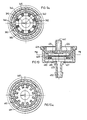
- Fig. 5 illustrates another type of flow-reducer element, generally designated 204, including a rigid plastic housing constituted of an outer rigid section 205 and an inner rigid section 206, and an embossed elastomeric member 207 which is deformable in response to the pressure on its opposite faces to regulate the flow through the element.
- the outer rigid section 205 is formed with a nipple 251, having an opening 252 therethrough, insertable into the respective discharge port of the tube (not shown) such that the opening 252 constitutes the inlet opening from the tube into the flow-reducer element.
- the rigid inner section 206 is also formed with a nipple 261 having an opening 262 therethrough, such that opening 262 serves as the outlet opening from the flow-reducer element.
- the inner rigid section 206 is further formed with a cavity 263 coaxial with both nipples 251 and 261 and the respective openings 252, 262.
- Cavity 263 is of cylindrical configuration
- the elastomeric member 207 is embossed with a cylindrical wall 271 fixed within cylindrical cavity 263, and with an elastomeric partition wall 272.
- One side of elastomeric partition wall 272 defines an inlet control chamber 273 with the outer rigid section 205 coaxial with the inlet opening 252 passing through nipple 251.
- the opposite side of elastomeric partition wall 272 defines an outlet control chamber 274 with the inner rigid section 206 coaxial with the outlet opening 262 through nipple 261.
- the outer face of the inner rigid section 206 is further formed with ribs 264 defining, with the inner face of the outer rigid section 205, a flow-reducing passageway or labyrinth 265 communicating, at one end, with the inlet control chamber 273, and at the opposite end with the outlet control chamber 274.
- the outlet control chamber 274 is expansible and contractible by the deformation of the partition wall 272 of the elastomeric member 207 to regulate the flow through it and out through the outlet opening 262 in response to flow.
- Any increase in the rate of flow reduces the pressure in the outlet control chamber 274, thereby causing the elastomeric partition wall 272 to deform inwardly, contracting the chamber, and thereby reducing the flow rate.
- the regulation is effected only in the outlet control chamber 274, as in the embodiment of Fig. 4.
- the inner face of the inner rigid section 206 is formed with a slot 266 extending to the outlet opening 262.
- Fig. 6 illustrates a variation in the construction, wherein the slot (corresponding to 266 in Fig. 5), assuring continuity of flow under high pressure conditions, is formed in the surface of the elastomeric partition 272 within the control chamber 274, as shown at 277, analagous to the construction illustrated in Figs. 3a and 3b.
- the flow-reducer element illustrated in Fig. 6 is constructed and operates in the same manner as the flow-reducer element 204 in Fig. 5.
- the drip irrigation emitter illustrated in Figs. 7 and 7a is of the "integrated-tube" type, in that a plurality of such emitters are integrated in a water supply tube, generally designated 302, formed with a plurality of discharge ports 303 spaced along the length of the tube, with the outlet of each emitter communicating with a discharge port of the tube.
- the emitter illustrated in Figs. 7 and 7a includes a housing formed at one end with an inlet 305 to communicate with the interior of the water supply tube 302, and with a plurality of ribs 306 engageable with the inner face of the tube to define a labyrinth flowpath 307.
- the emitter housing is formed with a cavity 308 communicating with flowpath 307 via an opening 309, and also communicating with the discharge port 303 via an outlet opening 310.
- An embossed elastomeric member 311 is fixed within cylindrical cavity 308, and defines an outlet control chamber 312 communicating with the outlet opening 310. The opposite face of the elastomeric member 311 communicates with the interior of the water supply tube 302.
- the embossed elastomeric member 311 is integrally formed with an annular rib 309 on its inner face, engageable with the flat inner face 312' of cavity 308, to space the member from the inner face of the cavity and thereby to define the outlet control chamber 312.
- the opposite face of elastomeric member 311 is integrally formed with another annular rib 313 which is received within an annular recess 314 formed in that end of the cavity 308.
- annular rib 313 is of decreasing thickness towards it outer edge to increase its deformation and thereby to enhance the seal.
- the pressurized water within the water supply tube 302 flows from the inlet 305 through the labyrinth flowpath 307 and opening 309, the outlet control chamber 312, outlet 310 and out through the discharge port 303.
- the labyrinth flowpath 307 reduces the flow through the discharge port 303, and the embossed elastomeric member 311, by its deformation in response to the difference in pressure on its opposite faces, regulates the flow through the outlet 310 to the discharge port 303.
- the inner face of the cylindrical cavity 308 is formed with a radial recess 320 to establish continuous communication with the outlet 310.
- the integrated-tube type emitter illustrated in Figs. 8 and 8a is substantially the same as described above with respect to Figs. 7 and 7a, and therefore the parts have been correspondingly numbered to facilitate understanding.
- the only difference in the construction illustrated in Figs. 2 and 2a is that the cavity, therein designated 308', receiving the embossed elastomeric member 311', is formed with an annular recess 315 on the side of the cavity facing the outlet control chamber 312 for stably fixing the member within the cavity and for producing the seal between the outlet control chamber 312 and the interior of the tube.
- Figs. 9 and 10 illustrate the invention as embodied in the "attached" type drip irrigation emitter which includes a nipple formed with the inlet of the emitter and insertable into the discharge port formed in the water supply tube.
- the drip irrigation emitter illustrated in Figs. 9 and 9a includes a plastic housing constituted of an outer rigid section 325 and an inner rigid section 326.
- the emitter further includes an embossed elastomeric member 327 which is deformable in response to the pressure on its opposite faces to regulate the flow through the emitter.
- the outer housing section 325 is formed with a nipple 351, having an opening 352 therethrough, insertable into a discharge port of a water supply tube such that the opening 352 constitutes the inlet into the emitter.
- the housing inner section 326 is also formed with a nipple 361 having an opening 362 therethrough, constituting the outlet from the emitter.
- the two sections 325, 326 are assembled together, with the elastomeric member 327 between them, by snapping an annular bead 326a on the outer face of the side wall of section 326 into an annular recess 325a in the inner face of the side wall of section 325.
- the inner housing section 326 is formed with an inner cylindrical cavity 363, and the outer face of section 326 is formed with ribs 364 defining, with the inner face of housing section 325, a labyrinth flowpath 365.
- This flowpath 365 communicates, at one end, with an inlet control chamber 373 within cavity 363 on one side of the elastomeric member 327 and communicating with the inlet 352.
- the opposite end of the labyrinth flowpath 365 communicates, via an opening 366, with the outlet control chamber 374 on the opposite side of the elastomeric member 327 and communicating with the outlet 362.
- Elastomeric member 327 is embossed with integrally formed relief formations on its opposite faces.
- annular rib 380 is integrally formed with an annular rib 380 around its periphery engageable with the surface of housing section 326 defining the cavity 363 in order to seal the inner control chamber 373 from the outer control chamber 374.
- annular rib 380 is of decreasing thickness towards its outer edge, thereby increasing the deformability of this rib and enhancing the seal produced between its outer edge and the inner surface of housing section 326.
- the outer surface of rib 380 is spaced from the inner surface of housing section 325, so as to better permit the outer edge of the rib to deflect firmly against the side wall of the cavity in housing section 326 and thereby to further enhance the seal.
- the relief formation on the opposite face of the embossed elastomeric member 327 comprises an annular array of projections 382, extending axially and spaced circumferentially as shown at 383, around member 307. Projections 382 have flat outer faces and engage the underface of housing section 326 to define the outlet control chamber 374.
- Elastomeric member 327 will thus be deformed towards and away from the mouth of outlet 362 in response to the difference in pressure in chambers 373 and 374.
- the deformability of the central part of the elastomeric member is increased by dishing its underface, as shown at 384.
- the underface of housing section 306 is formed with a radially-extending recess 390 to maintain communication between the outlet control chamber 374 and outlet 362 even under high inlet pressure conditions when the central dish portion 384 of the elastomeric member 327 may be pressed against the mouth of the outlet 362.
- the opposite side of the elastomeric member 427 is not formed with the spacing projections (382, in Figs. 9 and 9a), but rather the underface of housing section 426 is formed with these projections, as shown at 487.
- the projections are also disposed in an annular array and are circumferentially-spaced, to provide the spaces 489, in order to define the outlet control chamber 474 between the elastomeric member 427 and housing section 426.
Landscapes
- Life Sciences & Earth Sciences (AREA)
- Soil Sciences (AREA)
- Engineering & Computer Science (AREA)
- Water Supply & Treatment (AREA)
- Environmental Sciences (AREA)
- Nozzles (AREA)
- Infusion, Injection, And Reservoir Apparatuses (AREA)
Applications Claiming Priority (4)
| Application Number | Priority Date | Filing Date | Title |
|---|---|---|---|
| IL95138 | 1990-07-20 | ||
| IL95138A IL95138A (en) | 1990-07-20 | 1990-07-20 | Drip irrigation lines |
| IL9096164A IL96164A0 (en) | 1990-07-19 | 1990-10-29 | Drip irrigation emitter |
| IL96164 | 1990-10-29 |
Publications (3)
| Publication Number | Publication Date |
|---|---|
| EP0467386A2 true EP0467386A2 (fr) | 1992-01-22 |
| EP0467386A3 EP0467386A3 (en) | 1992-05-27 |
| EP0467386B1 EP0467386B1 (fr) | 1994-08-31 |
Family
ID=26322114
Family Applications (1)
| Application Number | Title | Priority Date | Filing Date |
|---|---|---|---|
| EP91112110A Expired - Lifetime EP0467386B1 (fr) | 1990-07-20 | 1991-07-19 | Emetteurs d'irrigation goutte à goutte |
Country Status (5)
| Country | Link |
|---|---|
| US (1) | US5183208A (fr) |
| EP (1) | EP0467386B1 (fr) |
| AU (1) | AU651356B2 (fr) |
| DE (1) | DE69103704T2 (fr) |
| ES (1) | ES2058998T3 (fr) |
Cited By (12)
| Publication number | Priority date | Publication date | Assignee | Title |
|---|---|---|---|---|
| US5294058A (en) * | 1992-01-24 | 1994-03-15 | Plastro-Gvat | Regulated drip irrigation emitter |
| EP0636309A1 (fr) * | 1993-07-30 | 1995-02-01 | Amir Cohen | Dispositif de restriction contrôlée de courant liquide particulièrement utile comme émetteur d'irrigation goutte à goutte |
| FR2709400A1 (fr) * | 1993-09-01 | 1995-03-10 | Jouglens Pierre | Dispositif goutte à goutte pour installation d'arrosage de cultures. |
| EP0659334A1 (fr) * | 1993-12-24 | 1995-06-28 | Hydromatic Ltd. | Réducteurs d'écoulement d'un fluide et émetteur d'irrigation goutte-à-goutte le comprenant |
| EP0791290A2 (fr) * | 1996-03-01 | 1997-08-27 | Amir Cohen | Dispositif de restriction contrÔlée de courant liquide pour irrigation goutte à goutte |
| US6027048A (en) * | 1997-10-14 | 2000-02-22 | Hydroplan Engineering Ltd. | Irrigation emitter unit |
| GR990100422A (el) * | 1999-12-08 | 2001-08-31 | Σταλακτης ποτισματος με αυτορυθμιση της πιεσης του νερου | |
| ES2191525A1 (es) * | 1997-12-28 | 2003-09-01 | Amir Cohen | "tuberias de riego por goteo" |
| EP1448313A1 (fr) * | 2001-11-26 | 2004-08-25 | Amir Cohen | Tuyau d'irrigation au goutte-a-goutte et son procede de fabrication |
| EP2856861A4 (fr) * | 2012-05-24 | 2016-01-20 | Enplas Corp | Goutteur pour arrosage au goutte-à-goutte et dispositif d'arrosage au goutte-à-goutte équipé de celui-ci |
| EP3087829A4 (fr) * | 2013-12-27 | 2017-08-23 | Enplas Corporation | Goutteur et tube d'irrigation goutte à goutte |
| CN112189538A (zh) * | 2020-09-30 | 2021-01-08 | 萧县年年养鱼农民专业合作社 | 一种节水型果蔬种植用灌溉装置 |
Families Citing this family (45)
| Publication number | Priority date | Publication date | Assignee | Title |
|---|---|---|---|---|
| US5333793A (en) * | 1993-07-21 | 1994-08-02 | T-Systems International, Inc. | Drip irrigation hose with pressure compensation and method for its manufacture |
| US5634594A (en) * | 1993-07-30 | 1997-06-03 | Cohen; Amir | Flow control device particularly useful in drip irrigation emitters |
| US5628462A (en) * | 1995-08-15 | 1997-05-13 | Miller; David B. | Drip irrigation emitter |
| US5688072A (en) * | 1995-12-14 | 1997-11-18 | Micro Irrigation Technologies, Inc. | Agricultural drip tape |
| ES2137825B1 (es) * | 1996-02-16 | 2000-08-16 | Twin Drops Iberica S A | Gotero autocompensante y antidescarga para riegos uniformes. |
| US6213408B1 (en) | 1999-11-18 | 2001-04-10 | Eureka Technologies Ltd | Flow regulator and corresponding method with pressure responsive flow regulation |
| US6736337B2 (en) | 2002-02-08 | 2004-05-18 | The Toro Company | Pressure compensating drip irrigation hose |
| WO2005115634A1 (fr) | 2004-05-24 | 2005-12-08 | Amir Cohen | Tuyau d'irrigation par goutte-a-goutte et son procede de fabrication |
| US8302887B2 (en) | 2005-03-31 | 2012-11-06 | Rain Bird Corporation | Drip emitter |
| US20070189852A1 (en) * | 2006-01-31 | 2007-08-16 | Greg Wolfley | Modular network irrigation system |
| US7648085B2 (en) | 2006-02-22 | 2010-01-19 | Rain Bird Corporation | Drip emitter |
| ES2328541B1 (es) * | 2006-11-08 | 2010-09-22 | Wind, S.L. | Proceso de fabricacion de un emisor para riego por goteo. |
| US8628032B2 (en) * | 2008-12-31 | 2014-01-14 | Rain Bird Corporation | Low flow irrigation emitter |
| US8439282B2 (en) * | 2009-02-06 | 2013-05-14 | Rain Bird Corporation | Low flow irrigation emitter |
| US8317111B2 (en) * | 2010-01-31 | 2012-11-27 | Amirim Products Development & Patents Ltd. | Bi-component drip emitter |
| GB2484924A (en) | 2010-10-25 | 2012-05-02 | Amirim Products Dev & Patents Ltd | An on line drip irrigation emitter having an inlet filtering dvice |
| IL212105A (en) | 2011-04-03 | 2016-07-31 | Einav Zvi | Integral dropper with elongated exit pool |
| US8511586B2 (en) | 2011-04-20 | 2013-08-20 | Deere & Company | Disc shaped regulated drip irrigation emitter |
| US20130248622A1 (en) | 2012-03-26 | 2013-09-26 | Jae Yung Kim | Drip line and emitter and methods relating to same |
| US9877440B2 (en) | 2012-03-26 | 2018-01-30 | Rain Bird Corporation | Elastomeric emitter and methods relating to same |
| US9485923B2 (en) | 2012-03-26 | 2016-11-08 | Rain Bird Corporation | Elastomeric emitter and methods relating to same |
| US10440903B2 (en) | 2012-03-26 | 2019-10-15 | Rain Bird Corporation | Drip line emitter and methods relating to same |
| IL221089A (en) * | 2012-07-24 | 2016-05-31 | Einav Zvi | Integral dropper with easy paddling exit pool |
| CN104684381B (zh) * | 2012-09-28 | 2017-05-10 | 恩普乐股份有限公司 | 滴灌用滴头及滴灌装置 |
| US9872444B2 (en) | 2013-03-15 | 2018-01-23 | Rain Bird Corporation | Drip emitter |
| US10869434B2 (en) | 2013-07-09 | 2020-12-22 | Amirim Products Development & Patents Ltd. | Elliptical in line button dripper with extended bonding zones |
| US9462760B2 (en) | 2013-07-09 | 2016-10-11 | Amirim Products Development & Patents Ltd. | In line button drip emitter |
| US9949448B2 (en) * | 2015-01-14 | 2018-04-24 | Amirim Products Development & Patents Ltd. | Modular in line button drip emitter system |
| US10631473B2 (en) | 2013-08-12 | 2020-04-28 | Rain Bird Corporation | Elastomeric emitter and methods relating to same |
| US10285342B2 (en) | 2013-08-12 | 2019-05-14 | Rain Bird Corporation | Elastomeric emitter and methods relating to same |
| USD811179S1 (en) | 2013-08-12 | 2018-02-27 | Rain Bird Corporation | Emitter part |
| JP6339338B2 (ja) * | 2013-08-26 | 2018-06-06 | 株式会社エンプラス | ドリッパおよび点滴灌漑用チューブ |
| US9883640B2 (en) | 2013-10-22 | 2018-02-06 | Rain Bird Corporation | Methods and apparatus for transporting elastomeric emitters and/or manufacturing drip lines |
| US10330559B2 (en) | 2014-09-11 | 2019-06-25 | Rain Bird Corporation | Methods and apparatus for checking emitter bonds in an irrigation drip line |
| CN108040458A (zh) * | 2015-09-17 | 2018-05-15 | 耐特菲姆有限公司 | 滴灌排出器和用于滴灌排出器的膜 |
| JP6689634B2 (ja) * | 2016-03-17 | 2020-04-28 | 株式会社エンプラス | エミッタおよび点滴灌漑用チューブ |
| CN107258475A (zh) | 2016-04-07 | 2017-10-20 | 阿米尔·科恩 | 内嵌式按钮滴灌灌水器 |
| US10375904B2 (en) | 2016-07-18 | 2019-08-13 | Rain Bird Corporation | Emitter locating system and related methods |
| WO2018140772A1 (fr) | 2017-01-27 | 2018-08-02 | Rain Bird Corporation | Éléments de compensation de pression, émetteurs, canalisation de goutte-à-goutte et procédés associés |
| US10626998B2 (en) | 2017-05-15 | 2020-04-21 | Rain Bird Corporation | Drip emitter with check valve |
| CN107821106B (zh) * | 2017-09-28 | 2023-06-09 | 大禹节水(天津)有限公司 | 一种滴灌用压力补偿式滴头 |
| USD883048S1 (en) | 2017-12-12 | 2020-05-05 | Rain Bird Corporation | Emitter part |
| US11793127B2 (en) | 2017-12-12 | 2023-10-24 | Netafim, Ltd. | Drip emitter having membrane with a non-planar portion protruding into regulating chamber recess |
| WO2019146528A1 (fr) * | 2018-01-23 | 2019-08-01 | 株式会社エンプラス | Goutteur et tube d'irrigation goutte à goutte |
| US11985924B2 (en) | 2018-06-11 | 2024-05-21 | Rain Bird Corporation | Emitter outlet, emitter, drip line and methods relating to same |
Citations (3)
| Publication number | Priority date | Publication date | Assignee | Title |
|---|---|---|---|---|
| FR2366790A1 (fr) * | 1976-10-10 | 1978-05-05 | Drori Mordeki | Dispositif d'irrigation goutte-a-goutte et regulateur de pression d'eau pour un tel dispositif |
| FR2469959A1 (fr) * | 1979-11-22 | 1981-05-29 | Hydro Plan Eng Ltd | Dispositif pour l'emission goutte a goutte de liquide |
| US4817875A (en) * | 1987-09-21 | 1989-04-04 | David Karmeli | Flexible pipe for trickle irrigation |
Family Cites Families (5)
| Publication number | Priority date | Publication date | Assignee | Title |
|---|---|---|---|---|
| US3998427A (en) * | 1975-12-11 | 1976-12-21 | Clarence Bentley | Self-cleaning drip irrigation valve |
| US4573640A (en) * | 1976-10-26 | 1986-03-04 | Hydro-Plan Engineering Ltd. | Irrigation emitter unit |
| NZ200960A (en) * | 1981-06-22 | 1985-11-08 | Ris Irrigation Syst | Drip feed device containing disc with tortuous flow paths on each side |
| AU8708382A (en) * | 1981-08-25 | 1983-05-12 | Wannan, I.R. | Drip irrigator |
| IL93255A (en) * | 1990-02-02 | 1997-03-18 | Plastro Gvat | Drip irrigation lines |
-
1991
- 1991-07-15 US US07/729,953 patent/US5183208A/en not_active Expired - Lifetime
- 1991-07-18 AU AU81107/91A patent/AU651356B2/en not_active Ceased
- 1991-07-19 ES ES91112110T patent/ES2058998T3/es not_active Expired - Lifetime
- 1991-07-19 DE DE69103704T patent/DE69103704T2/de not_active Expired - Fee Related
- 1991-07-19 EP EP91112110A patent/EP0467386B1/fr not_active Expired - Lifetime
Patent Citations (3)
| Publication number | Priority date | Publication date | Assignee | Title |
|---|---|---|---|---|
| FR2366790A1 (fr) * | 1976-10-10 | 1978-05-05 | Drori Mordeki | Dispositif d'irrigation goutte-a-goutte et regulateur de pression d'eau pour un tel dispositif |
| FR2469959A1 (fr) * | 1979-11-22 | 1981-05-29 | Hydro Plan Eng Ltd | Dispositif pour l'emission goutte a goutte de liquide |
| US4817875A (en) * | 1987-09-21 | 1989-04-04 | David Karmeli | Flexible pipe for trickle irrigation |
Cited By (20)
| Publication number | Priority date | Publication date | Assignee | Title |
|---|---|---|---|---|
| AU651514B2 (en) * | 1992-01-24 | 1994-07-21 | Plastro-Gvat Marketing (1990) Ltd. | Regulated drip irrigation emitter |
| US5294058A (en) * | 1992-01-24 | 1994-03-15 | Plastro-Gvat | Regulated drip irrigation emitter |
| EP0636309A1 (fr) * | 1993-07-30 | 1995-02-01 | Amir Cohen | Dispositif de restriction contrôlée de courant liquide particulièrement utile comme émetteur d'irrigation goutte à goutte |
| FR2709400A1 (fr) * | 1993-09-01 | 1995-03-10 | Jouglens Pierre | Dispositif goutte à goutte pour installation d'arrosage de cultures. |
| EP0659334A1 (fr) * | 1993-12-24 | 1995-06-28 | Hydromatic Ltd. | Réducteurs d'écoulement d'un fluide et émetteur d'irrigation goutte-à-goutte le comprenant |
| US5586727A (en) * | 1993-12-24 | 1996-12-24 | Hydromatic Ltd. | Flow reducer devices and drip irrigation emitter including same |
| EP0791290A2 (fr) * | 1996-03-01 | 1997-08-27 | Amir Cohen | Dispositif de restriction contrÔlée de courant liquide pour irrigation goutte à goutte |
| EP0791290A3 (fr) * | 1996-03-01 | 1997-09-03 | Amir Cohen | Dispositif de restriction contrôlée de courant liquide pour irrigation goutte à goutte |
| US6027048A (en) * | 1997-10-14 | 2000-02-22 | Hydroplan Engineering Ltd. | Irrigation emitter unit |
| US6206305B1 (en) | 1997-10-14 | 2001-03-27 | Hydroplan Engineering Ltd. | Irrigation emitter unit |
| ES2191525A1 (es) * | 1997-12-28 | 2003-09-01 | Amir Cohen | "tuberias de riego por goteo" |
| GR990100422A (el) * | 1999-12-08 | 2001-08-31 | Σταλακτης ποτισματος με αυτορυθμιση της πιεσης του νερου | |
| EP1448313A1 (fr) * | 2001-11-26 | 2004-08-25 | Amir Cohen | Tuyau d'irrigation au goutte-a-goutte et son procede de fabrication |
| EP1448313A4 (fr) * | 2001-11-26 | 2008-03-05 | Amir Cohen | Tuyau d'irrigation au goutte-a-goutte et son procede de fabrication |
| EP2856861A4 (fr) * | 2012-05-24 | 2016-01-20 | Enplas Corp | Goutteur pour arrosage au goutte-à-goutte et dispositif d'arrosage au goutte-à-goutte équipé de celui-ci |
| EP3097773A1 (fr) * | 2012-05-24 | 2016-11-30 | Enplas Corporation | Émetteur d'irrigation goutte-à-goutte et dispositif d'irrigation goutte-à-goutte équipé de celui-ci |
| US10219452B2 (en) | 2012-05-24 | 2019-03-05 | Enplas Corporation | Drip irrigation emitter and drip irrigation device equipped with same |
| EP3087829A4 (fr) * | 2013-12-27 | 2017-08-23 | Enplas Corporation | Goutteur et tube d'irrigation goutte à goutte |
| US10327396B2 (en) | 2013-12-27 | 2019-06-25 | Enplas Corporation | Emitter, and drip irrigation tube |
| CN112189538A (zh) * | 2020-09-30 | 2021-01-08 | 萧县年年养鱼农民专业合作社 | 一种节水型果蔬种植用灌溉装置 |
Also Published As
| Publication number | Publication date |
|---|---|
| DE69103704D1 (de) | 1994-10-06 |
| DE69103704T2 (de) | 1994-12-22 |
| AU8110791A (en) | 1992-01-23 |
| AU651356B2 (en) | 1994-07-21 |
| EP0467386A3 (en) | 1992-05-27 |
| ES2058998T3 (es) | 1994-11-01 |
| EP0467386B1 (fr) | 1994-08-31 |
| US5183208A (en) | 1993-02-02 |
Similar Documents
| Publication | Publication Date | Title |
|---|---|---|
| EP0467386B1 (fr) | Emetteurs d'irrigation goutte à goutte | |
| US5294058A (en) | Regulated drip irrigation emitter | |
| US5586727A (en) | Flow reducer devices and drip irrigation emitter including same | |
| US5400973A (en) | Pressure responsive regulated flow restrictor useful for drip irrigation | |
| US10455780B2 (en) | In line button drip emitter | |
| EP0444425B1 (fr) | Conduites d'irrigation goutte à goutte | |
| US4687143A (en) | Drip irrigation apparatus | |
| US4502631A (en) | Trickle irrigation unit | |
| AP43A (en) | "Flow regulating device." | |
| EP1435196B1 (fr) | Distributeur d'arrosage goutte-à-goutte amélioré | |
| US4210287A (en) | Drip irrigation system | |
| US5236130A (en) | Drip irrigation apparatus | |
| US5634594A (en) | Flow control device particularly useful in drip irrigation emitters | |
| US3767124A (en) | Self-flushing irrigating valve | |
| EP0343789B1 (fr) | Vanne en élastomère pour régler le débit dans des systèmes d'irrigation | |
| US4846406A (en) | Micro flow control valve for irrigation systems and method | |
| JP7101045B2 (ja) | エミッタおよび点滴灌漑用チューブ | |
| IL97564A (en) | Drip irrigation apparatus | |
| US4909441A (en) | Elastomeric flow control valve | |
| US4715543A (en) | Flow restrictor device particularly useful for drip irrigation | |
| US10869434B2 (en) | Elliptical in line button dripper with extended bonding zones | |
| USRE29022E (en) | Self-flushing irrigation valve | |
| EP0414977A2 (fr) | Petits pulvérisateurs pour l'irrigation |
Legal Events
| Date | Code | Title | Description |
|---|---|---|---|
| PUAI | Public reference made under article 153(3) epc to a published international application that has entered the european phase |
Free format text: ORIGINAL CODE: 0009012 |
|
| AK | Designated contracting states |
Kind code of ref document: A2 Designated state(s): DE ES FR GR IT NL |
|
| PUAL | Search report despatched |
Free format text: ORIGINAL CODE: 0009013 |
|
| AK | Designated contracting states |
Kind code of ref document: A3 Designated state(s): DE ES FR GR IT NL |
|
| 17P | Request for examination filed |
Effective date: 19921117 |
|
| 17Q | First examination report despatched |
Effective date: 19931119 |
|
| GRAA | (expected) grant |
Free format text: ORIGINAL CODE: 0009210 |
|
| AK | Designated contracting states |
Kind code of ref document: B1 Designated state(s): DE ES FR GR IT NL |
|
| REF | Corresponds to: |
Ref document number: 69103704 Country of ref document: DE Date of ref document: 19941006 |
|
| ITF | It: translation for a ep patent filed | ||
| ET | Fr: translation filed | ||
| REG | Reference to a national code |
Ref country code: GR Ref legal event code: FG4A Free format text: 3013909 |
|
| PLBE | No opposition filed within time limit |
Free format text: ORIGINAL CODE: 0009261 |
|
| STAA | Information on the status of an ep patent application or granted ep patent |
Free format text: STATUS: NO OPPOSITION FILED WITHIN TIME LIMIT |
|
| 26N | No opposition filed | ||
| NLS | Nl: assignments of ep-patents |
Owner name: PLASTRO GVAT |
|
| REG | Reference to a national code |
Ref country code: FR Ref legal event code: TP |
|
| REG | Reference to a national code |
Ref country code: ES Ref legal event code: PC2A Owner name: PLASTRO GVAT |
|
| PGFP | Annual fee paid to national office [announced via postgrant information from national office to epo] |
Ref country code: FR Payment date: 19970624 Year of fee payment: 7 |
|
| PGFP | Annual fee paid to national office [announced via postgrant information from national office to epo] |
Ref country code: NL Payment date: 19970630 Year of fee payment: 7 |
|
| PGFP | Annual fee paid to national office [announced via postgrant information from national office to epo] |
Ref country code: DE Payment date: 19970702 Year of fee payment: 7 |
|
| PGFP | Annual fee paid to national office [announced via postgrant information from national office to epo] |
Ref country code: ES Payment date: 19970718 Year of fee payment: 7 |
|
| PGFP | Annual fee paid to national office [announced via postgrant information from national office to epo] |
Ref country code: GR Payment date: 19970731 Year of fee payment: 7 |
|
| PG25 | Lapsed in a contracting state [announced via postgrant information from national office to epo] |
Ref country code: ES Free format text: LAPSE BECAUSE OF THE APPLICANT RENOUNCES Effective date: 19980720 |
|
| PG25 | Lapsed in a contracting state [announced via postgrant information from national office to epo] |
Ref country code: GR Free format text: LAPSE BECAUSE OF NON-PAYMENT OF DUE FEES Effective date: 19980731 |
|
| PG25 | Lapsed in a contracting state [announced via postgrant information from national office to epo] |
Ref country code: NL Free format text: LAPSE BECAUSE OF NON-PAYMENT OF DUE FEES Effective date: 19990201 |
|
| PG25 | Lapsed in a contracting state [announced via postgrant information from national office to epo] |
Ref country code: FR Free format text: LAPSE BECAUSE OF NON-PAYMENT OF DUE FEES Effective date: 19990331 |
|
| NLV4 | Nl: lapsed or anulled due to non-payment of the annual fee |
Effective date: 19990201 |
|
| PG25 | Lapsed in a contracting state [announced via postgrant information from national office to epo] |
Ref country code: DE Free format text: LAPSE BECAUSE OF NON-PAYMENT OF DUE FEES Effective date: 19990501 |
|
| REG | Reference to a national code |
Ref country code: FR Ref legal event code: ST |
|
| REG | Reference to a national code |
Ref country code: ES Ref legal event code: FD2A Effective date: 20001009 |
|
| PG25 | Lapsed in a contracting state [announced via postgrant information from national office to epo] |
Ref country code: IT Free format text: LAPSE BECAUSE OF NON-PAYMENT OF DUE FEES Effective date: 20050719 |