EP0467182B2 - Flatbed body - Google Patents
Flatbed body Download PDFInfo
- Publication number
- EP0467182B2 EP0467182B2 EP91111292A EP91111292A EP0467182B2 EP 0467182 B2 EP0467182 B2 EP 0467182B2 EP 91111292 A EP91111292 A EP 91111292A EP 91111292 A EP91111292 A EP 91111292A EP 0467182 B2 EP0467182 B2 EP 0467182B2
- Authority
- EP
- European Patent Office
- Prior art keywords
- profile
- frame
- profiles
- platform body
- tie rod
- Prior art date
- Legal status (The legal status is an assumption and is not a legal conclusion. Google has not performed a legal analysis and makes no representation as to the accuracy of the status listed.)
- Expired - Lifetime
Links
Images


Classifications
-
- B—PERFORMING OPERATIONS; TRANSPORTING
- B62—LAND VEHICLES FOR TRAVELLING OTHERWISE THAN ON RAILS
- B62D—MOTOR VEHICLES; TRAILERS
- B62D33/00—Superstructures for load-carrying vehicles
- B62D33/02—Platforms; Open load compartments
-
- B—PERFORMING OPERATIONS; TRANSPORTING
- B62—LAND VEHICLES FOR TRAVELLING OTHERWISE THAN ON RAILS
- B62D—MOTOR VEHICLES; TRAILERS
- B62D21/00—Understructures, i.e. chassis frame on which a vehicle body may be mounted
- B62D21/18—Understructures, i.e. chassis frame on which a vehicle body may be mounted characterised by the vehicle type and not provided for in groups B62D21/02 - B62D21/17
- B62D21/20—Understructures, i.e. chassis frame on which a vehicle body may be mounted characterised by the vehicle type and not provided for in groups B62D21/02 - B62D21/17 trailer type, i.e. a frame specifically constructed for use in a non-powered vehicle
-
- B—PERFORMING OPERATIONS; TRANSPORTING
- B62—LAND VEHICLES FOR TRAVELLING OTHERWISE THAN ON RAILS
- B62D—MOTOR VEHICLES; TRAILERS
- B62D29/00—Superstructures, understructures, or sub-units thereof, characterised by the material thereof
- B62D29/008—Superstructures, understructures, or sub-units thereof, characterised by the material thereof predominantly of light alloys, e.g. extruded
-
- B—PERFORMING OPERATIONS; TRANSPORTING
- B62—LAND VEHICLES FOR TRAVELLING OTHERWISE THAN ON RAILS
- B62D—MOTOR VEHICLES; TRAILERS
- B62D63/00—Motor vehicles or trailers not otherwise provided for
- B62D63/06—Trailers
- B62D63/08—Component parts or accessories
Definitions
- the invention relates to a platform body, preferably as a body for car trailers made of extruded profiles, preferably aluminum profiles consisting of at least two laterally arranged supporting longitudinal and front and rear crossbars, which together form a frame form.
- Such flatbed structures are made of, for example SE-B-0 458 267 and EP-A1-0 297 073 known. Extruded Profiles are used to assemble car beds used by means of screws.
- EP-A1-0 297 073 deals with a special configuration of the Corner post, while SE-B-0 458 267 is a mounting kit for car trailers.
- DE-U-83 36 029 and DE-U-82 29 145 are motor vehicle trailers known from extruded Light metal hollow profiles, the side walls made of there are one-piece side wall profiles and angled webs for Laying on the box bottom and for lateral reinforcement exhibit.
- the known platform bodies are consequently in The rear area is always welded.
- welds are subject to high static and dynamic loads , they must be carried out by specialists who have appropriate welding certificates. Form anyway the welds are the preferred target for Corrosion. It can also result from the welds different heat shrinkage tensions in the frame of the platform body, which are initiated Deform the platform.
- the welded frame is bulky and stressed a lot of space for temporary storage in production between the individual production stages. That in it tied up capital in the form of manufacturing costs affects the liquidity of the manufacturing company.
- the processing time of an order is disadvantageously long.
- the object of the invention is to build a platform to be specified, which has the shortest possible assembly time.
- the object of the invention is achieved in that the Structure of at least one arranged parallel to the cross member and with this by means of interlocking Has profile parts connected reinforcement profile and / or the reinforcement profile as a support for Beams formed shaped element, preferably two parallel webs, the reinforcing profile preferably parallel, arranged in the vertical direction Has webs, the distance of the width across flats one Screw head corresponds.
- the carrying capacity of a composite frame can thereby be further increased will.
- the beams bear one from a floor slab the beams initiated first into the Reinforcement profile and then on the cross bar from. By choosing different numbers of beams can individually adjust the load capacity of the platform body be adapted to the respective customer request.
- the head of the Screw with which joists are fastened in the reinforcement profile will prevent twisting during assembly secured.
- the object of the invention is also achieved in that it a profile of a crossbar insertable U-shaped Has profile, the clear width preferably the Wrench size corresponds to a screw head and that U-shaped profile preferably has legs whose Distance decreases towards the free ends.
- the object of the invention is in a platform body, made of extruded profiles, consisting of at least two laterally arranged load-bearing front and rear arranged cross bars, which together form a frame, the ends of the longitudinal spars and at least one Querholmes by means of at least one, over the entire Width of the frame extending, tie rod is braced, finally also solved in that the profile of the rear crossbar at least one closed Has hollow profile part for the tie rod and the profile of rear crossbar form elements for positive locking Inserting a hinge profile.
- the Platform body has a hinge profile, wherein in Hinge profile screwed eye bolts in accordingly arranged notches of a tubular Rear profile part are arranged engaging and by means one led through the tubular rear section Tie rods are pivotally fixed.
- the elastic modulus is higher than that of aluminum.
- crossbar profile and the reinforcement profile molded horizontal, against each other in vertical Has direction supporting profile surfaces and / or the Have profile grooves as molded scribe lines.
- This Measure serves to increase the load capacity, as both statically transfer the connected profile parts to the load. A Tearing out of the screw heads is avoided.
- the grooves reduce assembly times because they require the introduction of Holes in the profiles at the fastening points facilitate.
- the profile of the rear crossbar at least one closed hollow profile part has for tie rods.
- the closed hollow profile parts give the rear cross member greater stability and also protect the tie rods Corrosion and damage.
- the hinge profile preferably has parallel surfaces, the distance of which Wrench size corresponds to an eye screw nut.
- a hinge profile wherein eyebolts screwed into the hinge profile correspondingly arranged notches of a tubular rear profile part arranged engaging are and by means of a through the tubular Tension anchor guided in the rear profile section is pivotally fixed are.
- the tie rod is also advantageous used as an axis for the hinge.
- the eye bolts can be different Load capacities can be realized.
- the structure has a tarpaulin frame with corner posts and connecting them above Top edge profiles, these on their top Have U-shaped legs arranged horizontally, a bow profile between the ends are supported, the bow profile preferably is designed as a rectangular hollow profile part, preferably arranged on two adjacent sides Form elements that complement each other enable a positive connection.
- This Shortened formation of the tarpaulin top edge profile advantageous the assembly of bow profiles. By simply inserting a shorter section the indirect area can have the same profile of the tarpaulin frame so that after spreading the tarp the roof an incline for draining water.
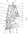
- the car trailer shown in Figure 1 shows a perspective view of a platform body 1, which is mounted on a chassis 2.
- the chassis 2 consists essentially of a drawbar with a towbar and one Axle with two wheels, the drawbar a "T" forming is connected to the axis test. From the chassis 2 is in perspective view only the front wheel 3 with fender 4 visible.
- a plate 5 forms the bottom of the platform. This is at the front through the front wall 6, laterally through the side walls 7 and rear through the Rear panel 8 limited. Using the front corner post 9 into which the front ends of the side walls 7 and the ends of the front wall 6 are inserted, the front wall 6 is connected to the side walls 7. The other end of the side walls 7 is in Tailgate profile 10 inserted, the side walls limit back.
- a rear cross member 13 connects the two Rear flank profiles 10 and the side walls 7 with each other.
- the tailgate 8 is by means of hinges 14 on rear cross member 13 pivotally attached.
- the Profile of the cross member 13 are the side rear lights 15 and reflective triangles 16 against Damage protected.
- the rear flanks 10 and the front corner posts 9 have insertion openings at their upper end 17 'in the corresponding counterparts shaped insertion ends 17 '' of a tarpaulin frame 19 (Fig. 2) can be introduced. This Openings are closed by caps, if there is no planned frame.
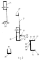
- the tarpaulin frame 19 shown in FIG. 2 consists of four vertically arranged corner posts 20, the corresponding insertion ends at their lower ends 17 '' for insertion into the insertion openings 17 'of the platform body 1 (Fig. 1).
- the top ends of the corner posts will be through tarpaulin edge profiles arranged in the longitudinal direction 21 and two transverse profiles 22 held together in table form. Between the tarpaulin edge profiles 21 extend bow profiles 23, which in Profiles 21 are inserted and on the turn fixed shorter ends of the bow profile are so that a tarpaulin put on a roof pitch receives, which allows water to drain off easily.
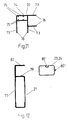
- FIG 3 the essential profiles of the Front wall 6 in accordance with section line III-III from FIG 1 shown individually.
- the front wall 6 exists from an upper wall profile 26 and a front profile, the front cross member 27 of the body forms.
- the front cross member 27 of the body forms.
- vertically aligned Crosspieces 28 'on the top of the front Crossbar 27 arranged, vertically aligned Bars 28 '' are pluggable, both can Profiles 26, 27 are interconnected.
- a hollow profile-like part 29, in the U-profile 30 can be inserted.
- the U-profile 30 points in the vertical direction 2 Leg 31, the distance of which is almost the Wrench size corresponds to a screw head. The decreases towards the open ends Distance slightly so far that in the end area the screw head is clamped.
- For Attaching the front crossbar to the Drawbars of a chassis are attached to the corresponding Place a or in the vertical direction introduced several holes in the hollow profile 29.
- the profile section receives the same drilling pattern of the U-profile 30.
- the screw heads of the mounting screws, whose stems towards the Show holes clamped and together with the section of the U-profile in the hollow profile 29 introduced until the drilling patterns coincide.
- Means a correspondingly shaped rod is then overcome the clamping force of the U-profile and pushed out the screws through the holes. This gives you secure attachment points with which the platform body is attached the drawbar or other parts of a chassis can be securely attached.
- the front cross member 27 is preferably included Shaped elements 32 ', 33' for the positive connection provided with a reinforcement profile 34.
- the reinforcement profile has the corresponding negative form elements 32 ′′, 33 ′′.
- the reinforcement profile 34 has for introducing loads into the front cross member horizontal surfaces 35 '' and 36 '' on each other on the corresponding counter surfaces 35 'and 36' support the front cross member 27.
- Two horizontal legs 37, 38 of the reinforcement profile 34 are spaced apart on, the height of that shown in Figure 6 Corresponds to the beam profile.
- the legs 37 and 38 thus serve as clamping points for the ends of the Beams 39, about the loads of the beams can be removed.
- the ends of the beams are made vertical Screws both legs 37 and 38 enforce the reinforcement profile, attached.
- the arranged on the leg 37 in the vertical direction Leg 40 prevent twisting of the screw head because the distance of the Wrench size of the fastening screw used corresponds.
- the base plate rests on its edges Web 41 and is preferably by means of self-drilling screws attached to the web 41.
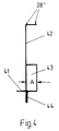
- Figure 4 shows a section through a lower one Side wall profile 42, which is the longitudinal spars of the body forms.
- a part designed as a hollow profile 43 contributes significantly to the strength of the side wall profile 42 at.
- a vertical web 44 molded.
- this web 44 are horizontal Holes drilled with the help of the platform body in the area of the axis to corresponding vertical arranged plates of the chassis screwed becomes. This vertical orientation has the Advantage that the screws are easily accessible and pollute less below the profile.
- web 41 is used for fastening the base plate 5.
- Figure 5 shows a section through a rear wall without tailgate according to section line V-V Figure 1 represents.
- the cross beam 13 consists of a vertical web 44 and two horizontal legs 45, which end as hollow profiles 46, 47.
- the hollow profile parts 46, 47 serve to accommodate in FIG. 5 Tie rods 18 (not shown) (FIG. 1).
- the upper profile parts 45, 46 have shaped elements 48 ', 49', with the help of which the corresponding negatively shaped elements 48 '' of a hinge profile 50 can be inserted with a positive fit can.
- a hinge part on the tailgate 51 is the tailgate 8, not shown attached.
- flap-side hinge profile 51 grooves 53 which serve as an auxiliary line for a hole the load-bearing capacity can also be achieved using the cross beam 13 a rear reinforcement profile 54 for higher loads are processed.
- the reinforcement profile 54 has legs 37, 38 and webs 40 accordingly the bow-side reinforcement profile 34 (Fig. 3) on.
- the joists are attached in the same way.
- the on the vertical webs 44 and 55 of the Profiles 13 and 54 provided shaped elements 56 ' and 57 'or 56' 'and 57' 'enable positive locking Connection of the two profiles 13, 54.
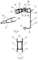
- FIG. 6 represents a hollow profile Beam 39 represents, the lower side by a lateral web 81 extended in the horizontal direction is. Chassis cable clamps can be attached to this bridge plug on and thus save time on cables mount for the rear lights.
- FIG. 7 shows a front corner post profile 9, to the parallel on two adjacent sides 83, 84 arranged webs 58, 59 are integrally formed.
- the distance the webs 58, 59 to one another are selected so that the front wall and side wall ends slightly in between can be introduced.
- FIG. 8 shows the corresponding profile for the Rear flank.
- the rear flank profile 10 only takes one end of the side wall 7 (Fig. 1) so that here only parallel to the side 60 of the profile 61 are integrally formed.
- the part shaped like a hollow profile 62 of the corner post 9 and the rear flank 10 is used as insertion opening 17 'for insertion ends 17' ' (Fig. 2) of a tarpaulin frame 9.
- Figure 9 is a modified cross member shown as rear profile 63.
- the rear profile 63 has the same Shaped elements 41 (Fig. 3) for supporting the Base plate 5, 56 'and 57' for inserting one Rear reinforcement profile 54 (Fig. 5), and a lower Leg 45 with hollow profile part 47 (Fig. 5).
- the Leg 45 opposite part to one Hollow box profile 64 designed, the outer cylindrical part for receiving an upper tie rod 18 serves.
- this tubular Profile part is a ramp hinge profile trained that from a hollow profile part 67 and two parallel legs 68 together.
- the hinge profile 66 on Rear profile 63 are centered by the surface 69 in 68 holes introduced in the direction of the legs and eyebolts 85 with the help of previously Hollow profile 67 inserted nuts 86 firmly screwed to the hinge profile 69. The distance the leg 68 is selected so that twisting an inserted nut 86 prevented becomes.
- the tubular profile part 65 of the rear profile is set 63 knocked out, so that the eyes of the Screws 85 with their centers to the longitudinal axis of the tubular profile part 65 stopped in alignment and then by introducing the shown Tie rod 18 can be locked.
- This design prevents Debris jamming the plate when Can cause swiveling.
- profiling 87 is provided only on one side and both that Hinge profile 66 and the ramp wedge profile 70 is symmetrical. Depending on the purpose can thus have a smooth or profiled surface to get voted.
- a ramp wedge profile 70 is preferably attached and connected to the ramp.
- the ramp wedge profile has the corresponding Bridges 68.
- the railing supports 11 essentially from a central hollow profile part 71 exist, the sides of which are vertical are extended above and below by webs 72. Between these webs, the top one will not railing profile shown and the upper edge the wall profile (Fig. 3) held. In the webs 72 grooves are molded in to aid insertion of holes. Shorter sections of this profile serve the railing 12 at individual points to connect the side walls 7.
- Figure 11 shows the rear post profile 20 of a Tarpaulin frame. It is composed of one Hollow profile part 74, into which four webs 75 protrude.
- the webs 75 delimit the corners of a square, the insertion end 17 '' (Fig. 2) envelops and serves as a clamp for their fixed ends.
- the Legs 76 and 78 are used to attach arranged at the top transverse profiles 22 or top edge profiles 21 (Fig. 2).
- grooves 73 are in turn molded in 12 shows a top edge profile 21, the Hollow profile part 77 by an extension of the wider side right-angled leg 82, one to the side has open U-shaped groove 79 which for Recording the bow profile 23 is used. How from As can be seen in FIG. 2, the bow profile 23 becomes rectangular arranged to the upper edge profile 21 and taken up by the groove 79 with the end.
- the Tile profile has a negative on adjacent sides and accordingly positively trained Shaped element 80 'or 80' ', so that two sections of the bow profile 23 rotated by 90 ° by means of the form elements 80 ', 80' ' can be connected.
- the location of the two twisted and pushed into each other Profiles 23 and 24 can be seen in Figure 2.
- the parts are glued together 23, 24 held in relation to each other.
- the platform structure according to the invention can with a low vertical range of manufacture advantageous within short assembly time.
- No assemblies are prefabricated, so that the space required for temporary storage larger assemblies and one otherwise associated capital commitment is advantageously low.
- the manufacturing lead time was significantly reduced.
- the system is advantageously easy to start adapt different load capacities.
Abstract
Description
Die Erfindung betrifft einen Pritschenaufbau, vorzugsweise als Aufbau für PKW-Anhänger aus stranggepreßten Profilen, vorzugsweise Aluminiumprofilen, bestehend aus mindestens zwei seitlich angeordneten tragenden Längs- und vorn und hinten angeordneten Querholmen, die zusammen einen Rahmen bilden.The invention relates to a platform body, preferably as a body for car trailers made of extruded profiles, preferably aluminum profiles consisting of at least two laterally arranged supporting longitudinal and front and rear crossbars, which together form a frame form.
Derartige Pritschenaufbauten sind beispielsweise aus SE-B-0 458 267 und EP-A1-0 297 073 bekannt. Stranggepreßte Profile werden dort zum Zusammenbau von PKW-Pritschen mittels Schrauben verwendet. Die Schrift EP-A1-0 297 073 befaßt sich mit einer speziellen Ausgestaltung des Eckpfostens, während die SE-B-0 458 267 einen Montagesatz für PKW-Anhänger beschreibt.Such flatbed structures are made of, for example SE-B-0 458 267 and EP-A1-0 297 073 known. Extruded Profiles are used to assemble car beds used by means of screws. The document EP-A1-0 297 073 deals with a special configuration of the Corner post, while SE-B-0 458 267 is a mounting kit for car trailers.
Aus DE-U-83 36 029 und DE-U-82 29 145 sind Kraftfahrzeug-Anhänger bekannt aus stranggepreßten Leichtmetallhohlprofilen, wobei die Bordwände aus einstückigen Bordwandprofilen bestehen und Winkelstege zum Auflegen des Kastenbodens sowie zur seitlichen Verstärkung aufweisen.DE-U-83 36 029 and DE-U-82 29 145 are motor vehicle trailers known from extruded Light metal hollow profiles, the side walls made of there are one-piece side wall profiles and angled webs for Laying on the box bottom and for lateral reinforcement exhibit.
Problematisch ist bei dem bekannten geschraubten Pritschenaufbau die Einzelteile so fest miteinander zu verbinden, daß sie ein den Anforderungen entsprechenden steifen Pritschenaufbau ergeben, der sich auch bei starken Vibrationen unter hohen Lasten nicht in seine Einzelteile zerlegt. Dabei stellt speziell die Heckpartie ein besonderes Problem dar, da dort die Bordwand zum Zwecke des Beladens U-förmig geöffnet ist. The problem with the known screwed Flatbed construction, the individual parts so tightly together connect that they meet the requirements stiff platform structure, which is even with strong Vibrations under high loads do not break into its individual parts disassembled. The rear section specifically adjusts is a special problem, since there the side wall for the purpose of Loading is opened in a U-shape.
Die bekannten Pritschenaufbauten werden folglich im Heckbereich stets verschweißt.The known platform bodies are consequently in The rear area is always welded.
Da die Schweißungen statisch und dynamisch hoch belastet sind, müssen sie von Fachkräften ausgeführt werden, die die entsprechenden Schweißzeugnisse besitzen. Trotzdem bilden gerade die Schweißungen bevorzugte Angriffspunkte für Korrosion. Außerdem können durch die Schweißungen infolge unterschiedlicher Wärmeschrumpfung Spannungen in den Rahmen des Pritschenaufbaus eingeleitet werden, die zu Verformungen der Pritsche führen.Because the welds are subject to high static and dynamic loads , they must be carried out by specialists who have appropriate welding certificates. Form anyway the welds are the preferred target for Corrosion. It can also result from the welds different heat shrinkage tensions in the frame of the platform body, which are initiated Deform the platform.
Wärmebehandlungen setzen dagegen Eigenspannungen des stranggepreßten Hohlprofils frei, die ebenfalls Ursache ähnlicher Verformungen sein können. Die Beseitigung derartiger Verformungen führt zu erheblichem Aufwand und Störungen im Fertigungsablauf. Schließlich härten Schweißungen auch erst nach einer gewissen Zeit vollkommen aus, so daß die zulässige Belastung des Pritschenaufbaus erst nach einiger Zeit erreicht wird. Es besteht deshalb seit langem das Bedürfnis nach einem Pritschenaufbau, der es ermöglicht, in der Massenfertigung ohne Schweißen auszukommen.Heat treatments, on the other hand, set the internal stresses of the extruded hollow profile free, which also cause similar deformations can be. The elimination such deformations leads to considerable effort and Disruptions in the manufacturing process. Finally harden Weldings only complete after a certain time off, so that the permissible load on the platform body is only reached after some time. Therefore it exists has long had the need for a platform body that it enables mass production without welding get along.
Je nach gewünschter Tragfähigkeit müssen unterschiedliche Profile für die Schweißkonstruktion des Rahmens verwendet werden. Der geschweißte Rahmen ist sperrig und beansprucht in der Fertigung viel Platz für seine Zwischenlagerung zwischen den einzelnen Fertigungsstufen. Das darin gebundene Kapital in Form von Fertigungskosten beeinträchtigt die Liquidität des Fertigungsunternehmens. Die Durchlaufzeit eines Auftrages ist nachteilig lang. Depending on the desired load capacity, different Profiles used for the welded construction of the frame will. The welded frame is bulky and stressed a lot of space for temporary storage in production between the individual production stages. That in it tied up capital in the form of manufacturing costs affects the liquidity of the manufacturing company. The processing time of an order is disadvantageously long.
Aufgabe der Erfindung ist es, einen Pritschenaufbau anzugeben, der eine möglichst geringe Montagezeit aufweist.The object of the invention is to build a platform to be specified, which has the shortest possible assembly time.
Die Aufgabe der Erfindung wird dadurch gelöst, daß der Aufbau mindestens ein parallel zum Querholm angeordnetes und mit diesem mittels förmschlüssig ineinandergreifender Profilteile verbundenes Verstärkungsprofil aufweist und/oder das Verstärkungsprofil ein als Auflager für Unterzüge ausgebildetes Formelement, vorzugsweise zwei parallel Stege aufweist, wobei das Verstärkungsprofil vorzugsweise parallele, in vertikaler Richtung angeordnete Stege aufweist, deren Abstand der Schlüsselweite eines Schraubenkopfes entspricht. Die Tragfähigkeit eines zusammengesetzten Rahmens kann hierdurch noch weiter erhöht werden. Die Unterzüge tragen eine von einer Bodenplatte auf die Unterzüge eingeleitetes Last zunächst in das Verstärkungsprofil ein und anschließend auf den Querholm ab. Durch Wahl unterschiedlicher Anzahlen von Unterzügen kann die Tragfähigkeit des Pritschenaufbaus individuell an den jeweiligen Kundenwunsch angepaßt werden. Der Kopf der Schraube, mit der Unterzüge im Verstärkungsprofil befestigt werden, wird hierdurch gegen Verdrehen bei der Montage gesichert.The object of the invention is achieved in that the Structure of at least one arranged parallel to the cross member and with this by means of interlocking Has profile parts connected reinforcement profile and / or the reinforcement profile as a support for Beams formed shaped element, preferably two parallel webs, the reinforcing profile preferably parallel, arranged in the vertical direction Has webs, the distance of the width across flats one Screw head corresponds. The carrying capacity of a composite frame can thereby be further increased will. The beams bear one from a floor slab the beams initiated first into the Reinforcement profile and then on the cross bar from. By choosing different numbers of beams can individually adjust the load capacity of the platform body be adapted to the respective customer request. The head of the Screw with which joists are fastened in the reinforcement profile will prevent twisting during assembly secured.
Die Aufgabe der Erfindung wird auch dadurch gelöst, daß er ein das Profil eines Querholmes einsteckbares U-förmiges Profil aufweist, dessen lichte Weite vorzugsweise der Schlüsselweite eines Schraubenkopfes entspricht und das U-förmige Profil vorzugsweise Schenkel aufweist, deren Abstand sich zu den freien Enden hin verringert. Hierdurch wird eine noch schnellere Montage und Befestigung des Pritschenaufbaus am Fahrgestell erreicht, da die einzuführenden Befestigungsschrauben mit ihren Köpfen während des Einführens sicher zwischen den freien Enden des U-förmigen Profils geklemmt werden.The object of the invention is also achieved in that it a profile of a crossbar insertable U-shaped Has profile, the clear width preferably the Wrench size corresponds to a screw head and that U-shaped profile preferably has legs whose Distance decreases towards the free ends. Hereby an even faster assembly and fastening of the Platform construction on the chassis achieved because the fastening screws to be inserted with their heads securely between the free ends during insertion of the U-shaped profile can be clamped.
Die Aufgabe der Erfindung wird bei einem Pritschenaufbau, aus stranggepreßten Profilen, bestehend aus mindestens zwei seitlich angeordneten tragenden Längs- vorn und hinten angeordneten Querholmen, die zusammen einen Rahmen bilden, wobei die Enden der Längsholme und mindestens eines Querholmes mittels mindestens eines, sich über die gesamte Breite des Rahmen erstreckenden, Zugankers verspannt wird, schließlich auch dadurch gelöst, daß das Profil des hinteren Querholms mindestens ein geschlossenes Hohlprofilteil für den Zuganker aufweist und das Profil des hinteren Querholms Formelemente zum formschlüssigen Einstecken eines Scharnierprofils aufweist.The object of the invention is in a platform body, made of extruded profiles, consisting of at least two laterally arranged load-bearing front and rear arranged cross bars, which together form a frame, the ends of the longitudinal spars and at least one Querholmes by means of at least one, over the entire Width of the frame extending, tie rod is braced, finally also solved in that the profile of the rear crossbar at least one closed Has hollow profile part for the tie rod and the profile of rear crossbar form elements for positive locking Inserting a hinge profile.
In alternativer Ausführung ist vorgesehen, daß der Pritschenaufbau ein Scharnierprofil aufweist, wobei im Scharnierprofil verschraubte Augenschrauben in entsprechend angeordnete Ausklinkungen eines rohrförmigen Heckprofilteils eingreifend angeordnet sind und mittels eines durch den rohrförmigen Heckprofilteil geführten Zugankers schwenkbar fixiert sind.In an alternative embodiment it is provided that the Platform body has a hinge profile, wherein in Hinge profile screwed eye bolts in accordingly arranged notches of a tubular Rear profile part are arranged engaging and by means one led through the tubular rear section Tie rods are pivotally fixed.
In Ausgestaltung der Erfindung ist für die beiden ersten Lösungen zusätzlich vorgesehen, daß die hinteren Enden der Längsholme und mindestens eines Querholms mittels mindestens eines, sich über die gesamte Breite des Rahmens erstreckenden, Zugankers verspannt werden.In an embodiment of the invention for the first two Solutions additionally provided that the rear ends of the Longitudinal spars and at least one cross spar by means of at least one, across the entire width of the frame extending, tie rod to be braced.
Es ergibt sich dadurch eine kraft- und formschlüssige Verbindung aller Teile im Heckbereich. Auch bei den auftretenden hohen Belastungen des Heckbereichs bleiben die einzelnen Teile überraschenderweise form- und kraftschlüssig zusammengefügt. Es kommt nicht, wie möglicherweise erwartet, zu einer Fugenbildung, die ihrerseits wieder zu unerwünschten Prall- und Schwingungseffekten bei dynamischer Beanspruchung führt. Dieses positive Verhalten der neuartige Fügeverbindung im Heckbereich des Pritschenaufbaus wird dadurch erklärt, daß durch den Zuganker, der sich über die gesamte Breite des Rahmens erstreckt, sich ein Dehnschraubeneffekt ergibt, der die einzelnen Teile so weit vorspannt, daß die aufgebrachte elastische Verformung auch bei höheren Belastungen und starken Schwingungen einer Fugenbildung zuverlässig entgegenwirkt.This results in a non-positive and positive fit Connection of all parts in the rear area. Even with the occurring high loads in the rear area remain individual parts surprisingly form and joined non-positively. It doesn't come how may be expected to form a joint in turn again to undesirable impact and Vibration effects with dynamic stress leads. This positive behavior of the new joint connection in the The rear area of the platform body is explained by the fact that through the tie rod, which extends over the entire width of the Extends frame, there is an expansion screw effect that the individual parts pre-stressed so far that the applied elastic deformation even with higher loads and strong vibrations of joint formation reliably counteracts.
Durch den Verzicht auf Schweißverbindungen entfällt die Notwendigkeit, vorgeschweißte tragende Rahmen in der Fertigung zwischenzulagern. Die zur Herstellung der Rahmen vorbereiteten Profilstäbe können direkt am Endmontageplatz gelagert werden. In der Endmontage wird als Fügeverfahren nur ein einziges Verfahren angewendet, nämlich Schrauben oder Nieten. Die Fertigungstiefe des Endprodukts verringert sich dadurch vorteilhaft. Da das Endprodukt nur an einem einzigen Montageplatz aus den fertig abgelängten Profilteilen, nämlich stranggepreßten Aluminiumprofilen,zusammengesetzt wird, verringert sich die Durchlaufzeit. Entsprechend verändert sich die Kaptialbindung.The absence of welded joints eliminates this Need to have pre-welded load-bearing frames in the Interim storage of production. The one for making the frame prepared profile bars can be placed directly at the final assembly station be stored. In the final assembly is used as a joining process only one method used, namely screws or rivets. The vertical range of manufacture of the end product is reduced advantageous. Since the end product is only on one only assembly place from the finished cut Profile parts, namely extruded Aluminum profiles, is reduced, the Lead time. The changes accordingly Capital bond.
Besonders vorteilhaft ist es, wenn der Zuganker aus einem Werkstoff besteht, dessen Elastizitätsmodul höher als der des Aluminiums ist.It when the tie rod from a Material exists, the elastic modulus is higher than that of aluminum.
In weiterer Ausgestaltung der Erfindung ist vorgesehen, daß das Profil des Querholms und das Verstärkungsprofil angeformte horizontale, sich gegeneinander in vertikaler Richtung abstützende Profilflächen aufweist und/oder die Profile Rillen als eingeformte Anrißlinien aufweisen. Diese Maßnahme dient der Erhöhung der Tragfähigkeit, da beide verbundenen Profilteile statisch die Last abtragen. Ein Ausreißen der Schraubenköpfe wird vermieden. Die Rillen verringern die Montagezeiten, weil sie das Einbringen von Bohrungen in die Profile an den Befestigungsstellen erleichtern.In a further embodiment of the invention it is provided that the crossbar profile and the reinforcement profile molded horizontal, against each other in vertical Has direction supporting profile surfaces and / or the Have profile grooves as molded scribe lines. This Measure serves to increase the load capacity, as both statically transfer the connected profile parts to the load. A Tearing out of the screw heads is avoided. The grooves reduce assembly times because they require the introduction of Holes in the profiles at the fastening points facilitate.
In weiterer Ausgestaltung der Erfindung ist vorgesehen, daß das Profil des hinteren Querholms mindestens ein geschlossenes Hohlprofilteil aufweist für Zuganker. Die geschlossenen Hohlprofilteile geben dem hinteren Querholm eine größere Stabilität und schützen auch die Zuganker vor Korrosionen und Beschädigungen. In a further embodiment of the invention it is provided that the profile of the rear crossbar at least one closed hollow profile part has for tie rods. The closed hollow profile parts give the rear cross member greater stability and also protect the tie rods Corrosion and damage.
In weiterer Ausgestaltung der Erfindung ist vorgesehen, daß das Heckprofil Formelemente zum formschlüssigen Einstecken eines Scharnierprofils aufweist. Das Scharnier läßt sich hierdurch besonders einfach durchAblängen von einer Profilstange und Einschieben in das Heckprofil herstellen und befestigen.In a further embodiment of the invention, that the rear profile shaped elements for form-fitting insertion of a hinge profile having. This makes the hinge particularly easy simply by cutting a profile bar and insert into the rear profile and fasten.
In weiterer Ausgestaltung der Erfindung ist vorgesehen, daß der Aufbau eine Auffahrplatte mit einem Auffahrkeilprooil und einem Scharnierprofil aufweist, wobei das Scharnierprofil vorzugsweise parallele Flächen aufweist, deren Abstand der Schlüsselweite eine Augenschraubenmutter entspricht. Dadurch läßt sich der Pritschenaufbau so ausgestalten, daß auch schwere Lasten über eine von der Auffahrplafte gebildete schiefe Ebene auf die Ladefläche bewegt werden können. Hierdurch lassen sich zur Montage des Scharniers standard-mäßige Augenschrauben verwenden, die sich mittels in das Scharnierprofil eingeschobener von Muttern einschrauben lassen, wobei das Sichern der Mutter gegen Verdrehen während der Montage vorteilhaft durch das entsprechend geformte Scharnierprofil erfolgt.In a further embodiment of the invention, that the construction with a ramp a ramp wedge profile and a hinge profile has, the hinge profile preferably has parallel surfaces, the distance of which Wrench size corresponds to an eye screw nut. This allows the platform structure to be built like this design that even heavy loads over a inclined plane formed by the ramp the loading area can be moved. Hereby can be used as standard for mounting the hinge Use eyebolts that can be fixed using nuts inserted into the hinge profile Have it screwed in, securing the Nut against twisting advantageous during assembly due to the correspondingly shaped hinge profile he follows.
In weiterer Ausgestaltung der Erfindung ist vorgesehen, daß er ein Scharnierprofil aufweist, wobei im Scharnierprofil verschraubte Ringschrauben in entsprechend angeordnete Ausklinkungen eines rohrförmigen Heckprofilteils eingreifend angeordnet sind und mittels eines durch den rohrförmigen Heckprofilteils geführten Zuganker schwenkbar fixient sind. Somit wird vorteilhaft der Zuganker auch als Achse für das Scharnier benutzt. Je nach Abstand der Augenschrauben können unterschiedliche Tragfähigkeiten verwirklicht werden.In a further embodiment of the invention, that it has a hinge profile, wherein eyebolts screwed into the hinge profile correspondingly arranged notches of a tubular rear profile part arranged engaging are and by means of a through the tubular Tension anchor guided in the rear profile section is pivotally fixed are. Thus the tie rod is also advantageous used as an axis for the hinge. Depending on the distance The eye bolts can be different Load capacities can be realized.
In weiterer Ausgestaltung der Erfindung ist vorgesehen, daß der Aufbau ein Planengestell aufweist mit Eckpfosten und diese oben verbindenden Oberkantenprofilen, wobei diese an ihrer Oberseite U-förmige horizontal angeordnete Schenkel aufweisen, zwischen denen Enden eine Spriegelprofils gehaltert sind, wobei das Spriegelprofil vorzugsweise als rechteckiges Hohlprofilteil ausgebildet ist, mit vorzugsweise an zwei benachbarten Seiten angeordneten Formelementen, die sich ergänzend eine formschlüssige Verbindung ermöglichen. Diese Ausbildung des Planenoberkantenprofils verkürzt vorteilhaft die Montage von Spriegelprofilen. Durch einfaches Einstecken eines kürzeren Abschnittes desselben Profils kann der mittelbare Bereich des Planengestells angehoben werden, damit nach Ausbreiten der Plane das Dach eine Neigung zum Ableiten von Wasser erhält.In a further embodiment of the invention, that the structure has a tarpaulin frame with corner posts and connecting them above Top edge profiles, these on their top Have U-shaped legs arranged horizontally, a bow profile between the ends are supported, the bow profile preferably is designed as a rectangular hollow profile part, preferably arranged on two adjacent sides Form elements that complement each other enable a positive connection. This Shortened formation of the tarpaulin top edge profile advantageous the assembly of bow profiles. By simply inserting a shorter section the indirect area can have the same profile of the tarpaulin frame so that after spreading the tarp the roof an incline for draining water.
Weitere Vorteile und erfindungswesentliche Merkmale ergeben sich aus der nachfolgenden Beschreibung einer bevorzugten Ausführungsform der Erfindung unter Bezugnahme auf die beigefügte Zeichnung, in der gleiche Teile mit denselben Bezugsziffern versehen sind. Die Figuren der Zeichnung zeigen im einzelnen:
- Fig. 1
- PKW-Anhänger,
- Fig. 2
- Planengestell in perspektivischer Ansicht,
- Fig. 3
- Schnitt durch ein Bugwandprofil gemäß
Schnittlinie III-III aus
Figur 1 in vereinzelter Darstellung, - Fig. 4
- Schnitt durch ein Seitenwandprofil
gemäß Schnittlinie IV-
IV aus Figur 1, - Fig. 5
- Schnitt durch eine Heckwand ohne Heckklappe gemäß Schnittlinle V-V aus Figur 1,
- Fig. 6
- Schnitt durch ein Unterzugprofil,
- Fig. 7
- Schnitt durch ein Heckpfostenprofil,
- Fig. 8
- Schnitt durch ein Eckflanckenprofil,
- Fig. 9
- Schnitt durch ein Heckprofil mit Scharnierprofil für eine Auffahrplatte,
- Fig. 10
- Schnitt durch ein Relingstüzenprofil,
- Fig. 11
- Schnitt durch ein Planengestelleckpfostenprofil,
- Fig. 12
- Schnitt durch ein Planengestelloberkantenprofil mit zugehörigem Spriegelprofil.
- Fig. 1
- Car trailer,
- Fig. 2
- Tarpaulin frame in perspective view,
- Fig. 3
- Section through a front wall profile according to section line III-III from Figure 1 in isolated representation,
- Fig. 4
- Section through a side wall profile according to section line IV-IV from Figure 1,
- Fig. 5
- Section through a rear wall without tailgate according to section line VV from Figure 1,
- Fig. 6
- Cut through a beam profile,
- Fig. 7
- Cut through a rear post profile,
- Fig. 8
- Cut through a corner flange profile,
- Fig. 9
- Section through a rear profile with a hinge profile for a ramp,
- Fig. 10
- Section through a railing column profile,
- Fig. 11
- Section through a tarpaulin frame post profile,
- Fig. 12
- Section through a tarpaulin frame top edge profile with the associated bow profile.
Der in Figur 1 dargestellte PKW-Anhänger
zeigt in perspektivischer Ansicht einen Pritschenaufbau
1, der auf einem Fahrgestell 2 montiert ist.
Das Fahrgestell 2 besteht im wesentlichen aus
einer Deichsel mit Anhängerkupplung und einer
Achse mit zwei Rädern, wobei die Deichsel ein "T"
bildende mit der Achse test verbunden ist. Von
dem Fahrgestell 2 ist in der perspektivischen Ansicht
nur das vordere Rad 3 mit Kotflügel 4 sichtbar.The car trailer shown in Figure 1
shows a perspective view of a
Den Boden der Pritsche bildet eine Platte 5.
Diese wird vorn durch die Bugwand 6, seitlich
durch die Seitenwände 7 und hinten durch die
Heckplatte 8 begrenzt. Mittels vorderer Eckpfosten
9, in die die vorderen Enden der Seitenwände 7
und die Enden der Bugwand 6 eingesteckt sind,
wird die Bugwand 6 mit den Seitenwänden 7 verbunden.
Das andere Ende der Seitenwände 7 ist in
Hecktlankenprofil 10 eingesteckt, die die Seitenwände
hinten begrenzen.A
Oberhalb der Bug- und Seitenwände 6, 7 ist
mittels vier Relingstützen 11, vorderen Eckpfosten
9 sowie Hecktlanken 10 eine U-förmig umlaufende
Reling 12 befestigt, die das Sichern von transportierten
Lasten erleichtert.Above the bow and
Ein hinterer Querholm 13 verbindet die beiden
Heckflankenprofile 10 und die Seitenwände 7 miteinander.A
Die Heckklappe 8 ist mittels Scharnieren 14 am
hinteren Querholm 13 schwenkbar befestigt. Im
Profil des Querholmes 13 sind die seitlichen Heckleuchten
15 und reflektierenden Dreiecke 16 gegen
Beschädigungen geschützt befestigt.The
Die Heckflanken 10 und die vorderen Eckpfosten
9 weisen an ihrem oberen Ende Einstecköffnungen
17' auf, in die als entsprechende Gegenstücke
geformte Einsteckenden 17'' eines Planengestells
19 (Fig. 2) eingeführt werden können. Diese
Öffnungen werden durch Kappen verschlossen,
falls kein Plangestell aufgesetzt ist.The rear flanks 10 and the
Um die Heckflanken 10 fest mit dem hinteren
Querholm 13 zu verspannen, sind zwei durch die
gesamte Länge des Querholms laufende Zuganker
mit Hutmuttern 18 vorgesehen, die als Gewindestangen
ausgebildet sind. To the
Das in Figur 2 dargestellte Planengestell 19
besteht aus vier vertikal angeordneten Eckpfosten
20, die an ihren unteren Enden entsprechende Einsteckenden
17'' für das Einführen in die Einstecköffnungen
17' des Pritschenaufbaus 1 (Fig. 1) aufweisen.
Die oberen Enden der Eckpfosten werden
durch in Längsrichtung angeordnete Planenkantenprofile
21 und zwei Querprofile 22 tischförmig zusammengehalten.
Zwischen den Planenkantenprofilen
21 erstrecken sich Spriegelprofile 23, die in
Profile 21 eingesteckt sind und auf denen wiederum
kürzere Enden des Spriegelprofils befestigt
sind, damit eine übergestülpte Plane eine Dachneigung
erhält, die Wasser leicht abfließen läßt.The
Zur Verstärkung des Gestells werden die
Eckpfosten 20 im unteren Bereich mittels Relingprofilen
25 U-förmig verbunden.To reinforce the frame, the
Corner posts 20 in the lower area using
In Figur 3 sind die wesentlichen Profile der
Bugwand 6 entsprechend Schnittlinie III-III aus Figur
1 vereinzelt dargestellt. Die Bugwand 6 besteht
aus einem oberen Wandprofil 26 und einem Bugprofil,
das den vorderen Querholm 27 des Aufbaus
bildet. Durch die im unteren Ende des oberen
Wandprofils angeordneten, vertikal ausgerichteten
Stege 28', die auf die am oberen Ende des vorderen
Querholms 27 angeordneten, vertikal ausgerichteten
Stege 28'' steckbar sind, können beide
Profile 26, 27 miteinander verbunden werden. Im
unteren Bereich des vorderen Querholms 27 befindet
sich ein hohlprofilartiger Teil 29, in den U-Profil
30 eingesteckt werden kann.In Figure 3, the essential profiles of the
Das U-Profil 30 weist in vertikaler Richtung 2
Schenkel 31 auf, deren Abstand nahezu der
Schlüsselweite eines Schraubenkopfes entspricht.
Zu den geöffneten Enden hin verringert sich der
Abstand geringfugig soweit, daß im Endbereich
eine Klemmung des Schraubenkopfes erfolgt. Zur
Befestigung des Vorderen Querholmss an der
Deichsel eines Fahrgestells, werden an entsprechender
Stelle in vertikaler Richtung eine oder
mehrere Bohrungen in das Hohlprofil 29 eingebracht.
Das gleiche Bohrbild erhält der Profilabschnitt
des U-Profils 30. An den Stellen der Bohrungen
werden die Schraubenköpfe der Befestigungsschrauben,
deren Schäfte in Richtung der
Bohrungen weisen, festgeklemmt und zusammen
mit dem Abschnitt des U-Profils in das Hohlprofil
29 eingeführt bis sich die Bohrbilder decken. Mittels
einer entsprechend geformten Stange wird anschließend
die Klemmkraft des U-Profils überwunden
und die Schrauben durch die Bohrungen herausgedrückt.
Dadurch erhält man sichere Befestigungspunkte,
mit denen der Pritschenaufbau an
der Deichsel oder an anderen Teilen eines Fahrgestells
sicher befestigt werden kann.The U-profile 30 points in the
Vorzugsweise ist der vordere Querholm 27 mit
Formelementen 32', 33' für die formschlüssige Verbindung
mit einem Verstärkungsprofil 34 versehen.
Das Verstärkungsprofil weist dazu die entsprechenden
negativen Formelemente 32'', 33'' auf. Mit
Hilfe dieser Formelemente 32, 33 lassen sich die
beiden Profile formschlüssig ineinanderfügen. Je
nach gewünschter Tragfähigkeit des Anhängers
kann die Tragfähigkeit des vorderen Querholms
verstärkt werden. Das Verstärkungsprofil 34 weist
zum Einleiten von Lasten in den vorderen Querholm
horizontale Flächen 35'' und 36'' auf, die sich
auf den entsprechenden Gegenflächen 35' und 36'
des vorderen Querholmss 27 abstützen.The
Zwei horizontale Schenkel 37, 38 des Verstärkungsprofil
34 weisen einen Abstand zueinander
auf, der der Höhe des in Figur 6 dargestellten
Unterzugprofils entspricht. Die Schenkel 37 und 38
dienen somit als Einspannstellen für die Enden der
Unterzüge 39, über die die Lasten der Unterzüge
abgetragen werden können.Two
Die Enden der Unterzüge werden mittels vertikaler
Schrauben, die beide Schenkel 37 und 38
des Verstärkungsprofils durchsetzen, befestigt. Die
am Schenkel 37 in vertikaler Richtung angeordneten
Schenkel 40 verhindern dabei ein Verdrehen
des Schraubenkopfes, weil der Abstand der
Schlüsselweite der verwendeten Befestigungsschraube
entspricht.The ends of the beams are made vertical
Screws both
Die in dieser Figur nicht dargestellte Bodenplatte
5 (Fig. 1) stützt sich an ihren Rändern auf
Steg 41 ab und ist vorzugsweise mittels Bohrschrauben
am Steg 41 befestigt.The base plate, not shown in this figure
5 (Fig. 1) rests on its
Figur 4 zeigt einen Schnitt durch ein unteres
Seitenwandprofil 42, das die Längsholme des Aufbaus
bildet. Ein als Hohlprofil 43 ausgeführter Teil
trägt wesentlich zur Festigkeit des Seitenwandprofils
42 bei. Am unteren Ende ist ein vertikaler Steg
44 angeformt. In diesen Steg 44 werden horizontale
Löcher gebohrt, mit deren Hilfe der Pritschenaufbau
im Bereich der Achse an entsprechende vertikal
angeordnete Platten des Fahrgestells angeschraubt
wird. Diese vertikale Ausrichtung hat den
Vorteil, daß die Schrauben leicht zugänglich sind
und unterhalb des Profils weniger verschmutzen.
Steg 41 dient, wie bereits beschrieben, der Befestigung
der Bodenplatte 5.Figure 4 shows a section through a lower one
Figur 5 stellt einen Schnitt durch eine Heckwand
ohne Heckklappe gemäß Schnittlinie V-V aus
Figur 1 dar. Der Querholm 13 besteht aus einem
vertikalen Steg 44 und zwei horizontalen Schenkeln
45, die als Hohlprofile 46, 47 enden. Die Hohlprofilteile
46, 47 dienen zur Aufnahme von in Figur 5
nicht dargestellten Zugankern 18 (Fig. 1).Figure 5 shows a section through a rear wall
without tailgate according to section line V-V
Figure 1 represents. The
Die oberen Profilteile 45, 46 weisen Formelemente
48', 49' auf, mit deren Hilfe die entsprechenden
negativ geformten Elemente 48'' eines Scharnierprofils
50 formschlüssig eingesteckt werden
können. Mit Hilfe eines heckklappenseitigen Scharnierteils
51 wird die nicht dargestellte Heckklappe 8
befestigt. Dabei werden zwei kurze Abschnitte der
Profile 50, 51 von einer nicht dargestellten Schraube,
die durch Bohrung 52 eingesteckt wird, axial
und radial aber schwenkbar gehaltert. Um die Befestigung
der Heckklappe zu erleichtern, weist das
klappenseitige Scharnierprofil 51 Rillen 53 auf, die
als Hilfslinie für eine Bohrung dienen.Zur Erhöhung
der Tragfähigkeit kann auch der Querholm 13 mittels
eines Heckverstärkungsprofils 54für höhere Lasten
verarbeitet werden. Das Verstärkungsprofil 54
weist Schenkel 37, 38 sowie Stege 40 entsprechend
dem bugseitigen Verstärkungsprofil 34 (Fig.
3) auf. Die Befestigung von Unterzügen erfolgt analog.
Die an den vertikalen Stegen 44 und 55 der
Profile 13 bzw. 54 vorgesehenen Formelemente 56'
und 57' bzw. 56'' und 57'' ermöglichen die formschlüssige
Verbindung der beiden Profile 13, 54.The
Figur 6 stellt ein als Hohlprofil ausgebildeten
Unterzug 39 dar, dessen untere Seite durch einen
seitlichen Steg 81 in horizontaler Richtung verlängert
ist. Auf diesen Steg lassen sich Chassiskabelklemmen
aufstecken und dadurch zeitsparend Kabel
für die Heckleuchten montieren.FIG. 6 represents a
Figur 7 zeigt ein vorderes Eckpfostenprofil 9,
an das an zwei benachbarten Seiten 83, 84 parallel
angeordnete Stege 58, 59 angeformt sind. Der Abstand
der Stege 58, 59 zueinander ist so gewählt,
daß die Bugwand und Seitenwandenden leicht dazwischen
eingeführt werden können. Mittels die
Stege und Seitenwandprofile durchsetzenden
Schrauben wird eine stabile Eckverbindung erreicht.FIG. 7 shows a front
Figur 8 zeigt das entsprechende Profil für die
Heckflanke. Das Heckflankenprofil 10 nimmt lediglich
ein Ende der Seitenwand 7 (Fig. 1) auf, so daß
hier nur an die Seite 60 des Profils parallele Stege
61 angeformt sind. Der hohlprofilartig geformte Teil
62 des Eckpfostens 9 und der Heckflanke 10 dient
als Einstecköffnung 17' für die Einsteckenden 17''
(Fig. 2) eines Planengestells 9.In Figur 9 ist ein
modifizierter Querholm als Heckprofil 63 dargestellt.
Wie in Figur 5 weist das Heckprofil 63 dieselben
Formelemente 41 (Fig. 3) zur Auflage der
Bodenplatte 5, 56' und 57' zum Einstecken eines
Heckverstärkungsprofils 54 (Fig. 5), und einen unteren
Schenkel 45 mit Hohlprofilteil 47 auf (Fig. 5).
Im oberen Bereich des Heckprofils 63 ist der dem
Schenkel 45 gegenüberliegende Teil zu einem
Hohlkastenprofil 64 ausgestaltet, dessen äußerer
zylindrischer Teil zur Aufnahme eines oberen Zugankers
18 dient. Als Gegenstück zu diesem rohrförmigen
Profilteil ist ein Auffahrrampenscharnierprofil
ausgebildet, daß sich aus einem Hohlprofilteil
67 und zwei parallelen Schenkeln 68 zusammensetzt.
Zur Befestigung des Scharnierprofils 66 am
Heckprofil 63 werden durch die Fläche 69 mittig in
Richtung der Schenkel 68 Bohrungen eingebracht
und Augenschrauben 85 mit Hilfe zuvor in das
Hohlprofil 67 eingebrachter Muttern 86 fest mit
dem Scharnierprofil 69 verschraubt. Der Abstand
der Schenkel 68 ist so gewählt, daß ein Verdrehen
einer eingeführten Schraubenmutter 86 verhindert
wird. An den den Schrauben 85 entsprechenden
Stellen wird der rohrförmige Profilteil 65 des Heckprofils
63 ausgeklingt, so daß die Augen der
Schrauben 85 mit ihren Zentren mit der Langsachse
des rohrförmigen Profilteils 65 fluchtend angehalten
und anschließend durch Einführen des dargestellten
Zugankers 18 verriegelt werden können.
Durch diese Gestaltung wird verhindert, daß
Schmutzteilchen ein Verklemmen der Platte beim
Schwenken verursachen können.Figure 8 shows the corresponding profile for the
Rear flank. The
Besonders vorteilhaft ist, daß die Profilierung
87 nur einseitig vorgesehen ist und sowohl das
Scharnierprofil 66 als auch das Auffahrkeilprofil 70
symmetrischausgebildet ist. Je nach Verwendungszweck
kann somit eine glatte oder profilierte Oberfläche
gewählt werden.It is particularly advantageous that the
Zwischen den parallelen Schenkeln 68 des
Scharnierteils 66 wird eine Platte entsprechender
Dicke eingefügt und mittels Durchgangsschrauben
fest mit dem Scharnierteil verbunden.Between the
Auf die gegenüberliegende Kante der Auffahrplatte
ist vorzugsweise ein Auffahrkeilprofil 70 aufgesteckt
und mit der Auffahrplatte verbunden. Zu
diesem Zweck weist das Auffahrkeilprofil die entsprechenden
Stege 68 auf.On the opposite edge of the ramp
a
In Figur 10 ist zu erkennen, daß die Relingstützen
11 im wesentlichen aus einem mittleren Hohlprofilteil
71 bestehen, dessen Seiten vertikal nach
oben und unten durch Stege 72 verlängert sind.
Zwischen diesen Stegen werden das obere nicht
dargestellte Relingsprofil sowie die obere Kante
des Wandprofils (Fig. 3) gehalten. In die Stege 72
sind Rillen eingeformt als Hilfe beim Einbringen
von Bohrungen. Kürzere Abschnitte dieses Profils
dienen dazu, an einzelnen Stellen die Reling 12 mit
den Seitenwänden 7 zu verbinden.In Figure 10 it can be seen that the railing supports
11 essentially from a central
Figur 11 zeigt das Heckpfostenprofil 20 eines
Planengestells. Es setzt sich zusammen aus einem
Hohlprofilteil 74, in das vier Stege 75 hineinragen.Figure 11 shows the
Die Stege 75 begrenzen die Ecken eine Quadrats,
das Einsteckenden 17'' (Fig. 2) umhüllt und
als Einspannung für deren feste Enden dient. Die
Schenkel 76 und 78 dienen der Befestigung von
oben angeordneten Querprofilen 22 bzw. Planoberkantenprofilen
21 (Fig. 2). Zum Anbringen von Bohrungen
sind wiederum Rillen 73 eingeformt.Figur
12 stellt ein Planoberkantenprofil 21 dar, dessen
Hohlprofilteil 77 durch ein die breitere Seite verlängernden
rechtwinkligen Schenkel 82, eine zur Seite
hin geöffnete U-förmige Nut 79 aufweist, die zur
Aufnahme des Spriegelprofils 23 dient. Wie aus
Figur 2 ersichtlich, wird das Spriegelprofil 23 rechtwinklig
zum Oberkantenprofil 21 angeordnet und
von der Nut 79 mit dem Ende aufgenommen. Das
Spriegelprofil weist an benachbarten Seiten ein negatives
und entsprechend positiv ausgebildetes
Formelement 80' bzw. 80'' auf, so daß zwei Abschnitte
des Spriegelprofils 23 um 90° verdreht
mittels der Formelemente 80', 80'' formschlüssig
miteinander verbunden werden können. Die Lage
der beiden um 90° verdrehten und ineinandergeschobenen
Profile 23 und 24 ist aus Figur 2 ersichtlich.
Durch Klebeverbindungen werden die Teile
23, 24 in ihrer Lage zueinander gehalten.The
Der erfindungsgemäße Pritschenaufbau kann bei geringer Fertigungstiefe vorteilhaft innerhalb kurzer Montagezeit fertiggestellt werden. Bei der Montage werden keinerlei Baugruppen vorgefertigt, so daß der Platzverbrauch für die Zwischenlagerung größerer Baugruppen und eine damit sonst verbundene Kapitalbindung vorteilhaft gering ist. Mit Hilfe des erfindungsgemäßen Profilsystems wurde die Fertigungsdurchlaufzeit wesentlich verringert. Das System läßt sich vorteilhaft einfach an unterschiedliche Tragfähigkeiten anpassen. The platform structure according to the invention can with a low vertical range of manufacture advantageous within short assembly time. In the No assemblies are prefabricated, so that the space required for temporary storage larger assemblies and one otherwise associated capital commitment is advantageously low. With the help of the profile system according to the invention the manufacturing lead time was significantly reduced. The system is advantageously easy to start adapt different load capacities.
- 11
- PritschenaufbauFlatbed construction
- 22nd
- Fahrgestellchassis
- 33rd
- Radwheel
- 44th
- Kotflügelfender
- 55
- BodenplatteBase plate
- 66
- BugwandBow wall
- 77
- SeitenwandSide wall
- 88th
- HeckklappeTailgate
- 99
- EckpfostenCorner post
- 1010th
- HeckflankenprofilRear flank profile
- 1111
- RelingsstützeRailing support
- 1212th
- RelingRailing
- 1313
- QuerholmQuerholm
- 1414
- Scharnierhinge
- 1515
- HeckleuchteRear light
- 1616
- Dreiecktriangle
- 17'17 '
- EinstecköffnungenInsertion openings
- 17''17 ''
- EinsteckendeInsertable
- 1818th
- ZugankerTie rod
- 1919th
- PlanengestellTarpaulin frame
- 2020th
- EckpfostenCorner post
- 2121
- PlanenkantenprofilTarpaulin edge profile
- 2222
- QuerprofilCross section
- 2323
- SpriegelprofilBow profile
- 2424th
- SpriegelprofilBow profile
- 2525th
- RelingsprofilRailing profile
- 2626
- oberes Wandprofilupper wall profile
- 2727
- vorderer Querholmfront cross member
- 28'28 '
- StegeWalkways
- 28''28 ''
- StegeWalkways
- 2929
- HohlprofilteilHollow profile part
- 3030th
- U-ProfilU profile
- 3131
- Schenkelleg
- 3232
- FormelementShaped element
- 3333
- FormelementShaped element
- 3434
- VerstärkungsprofilReinforcement profile
- 3535
- Flächesurface
- 3636
- Flächesurface
- 3737
- Schenkelleg
- 3838
- Schenkelleg
- 4040
- StegeWalkways
- 4141
- StegeWalkways
- 4242
- unteres Seitenwandprofillower sidewall profile
- 4343
- HohlprofilteilHollow profile part
- 4444
- Stegweb
- 4545
- Schenkelleg
- 4646
- HohlprofilteileHollow profile parts
- 4747
- HohlprofilteileHollow profile parts
- 4848
- FormelementShaped element
- 4949
- FormelementShaped element
- 5050
- ScharnierprofilHinge profile
- 5151
- klappseitiges Scharnierteilhinged hinge part
- 5252
- BohrungenHoles
- 5353
- Rillegroove
- 54'54 '
- HeckverstärkungsprofilRear reinforcement profile
- 5555
- Stegweb
- 3939
- UnterzugBeam
- 8181
- Stegweb
- 5656
- FormelementShaped element
- 5757
- FormelementShaped element
- 5858
- StegeWalkways
- 5959
- StegeWalkways
- 8383
- Seitenpages
- 8484
- Seitenpages
- 6060
- Seitepage
- 6161
- StegeWalkways
- 6262
- HohlprofilteilHollow profile part
- 6363
- HeckprofilteilRear profile part
- 6464
- HohlkastenprofilBox girder profile
- 6565
- zylindrisches Profilteilcylindrical profile part
- 6666
- ScharnierprofilHinge profile
- 6767
- HohlprofilteilHollow profile part
- 6868
- Schenkelleg
- 6969
- Flächesurface
- 7070
- AuffahrkeilprofilRamp wedge profile
- 8585
- AugenschraubeEye bolt
- 8686
- Muttermother
- 8787
- ProfilstegProfile web
- 7171
- HohlprofilHollow profile
- 7272
- StegeWalkways
- 7373
- Rille (Fig. 5)Groove (Fig. 5)
- 7474
- HohlprofilteilHollow profile part
- 7575
- StegeWalkways
- 7676
- Schenkelleg
- 7777
- HohlprofilteilHollow profile part
- 7878
- Schenkel (Fig. 12)Thigh (Fig. 12)
- 7979
- NutGroove
- 8080
- FormelementeForm elements
- 8282
- Stegweb
Claims (9)
- A platform body, preferably as a body for automobile trailers, made of extruded profiles, preferably aluminium profiles, comprising at least two laterally arranged supporting longitudinal beams and front and rear cross beams, which together form a frame, characterised in that the body comprises at least one reinforcing profile (34, 54), which is arranged parallel to the cross beam (27, 13) and is connected thereto by means of profile parts (32', 32'', 33', 33'', 56', 56'', 57', 57'') engaging in one another in a positive-locking manner, and/or the reinforcing profile (34) comprises a shaped element, preferably two parallel webs (37, 38), constructed as a support for trusses (39), the reinforcing profile (34, 54) preferably comprising parallel limbs (40) arranged in the vertical direction, whose spacing corresponds to the width of a screw head.
- A platform body, preferably as a body for automobile trailers, made of extruded profiles, preferably aluminium profiles, comprising at least two laterally arranged supporting longitudinal beams and front and rear cross beams, which together form a frame, characterised in that the body comprises a U-shaped profile (30), which is insertable into the profile of a cross beam (27) and whose free width corresponds to the width of a screw head, and the U-shaped profile (30) comprises limbs (31), whose spacing decreases in the direction of the free ends.
- A platform body, preferably as a body for automobile trailers, made of extruded profiles, preferably aluminium profiles, comprising at least two laterally arranged supporting longitudinal beams and front and rear cross beams, which together form a frame, the ends of the longitudinal beams (7, 42) and at least one cross beam (13) being clamped by means of at least one tie rod (18) extending over the entire width of the frame, characterised in that the profile of the rear cross beam (13) comprises at least one closed hollow profile part (46, 47) for the tie rod (18) and the profile of the rear cross beam (13) comprises shaped elements (48', 49') for the positive-locking insertion of a hinge profile (50).
- A platform body, preferably as a body for automobile trailers, made of extruded profiles, preferably aluminium profiles, comprising at least two laterally arranged supporting longitudinal beams and front and rear cross beams, which together form a frame, the ends of the longitudinal beams (7, 42) and at least one cross beam (13) being clamped by means of at least one tie rod (18) extending over the entire width of the frame, characterised in that the platform body comprises a hinge profile, eyebolts (85) screwed into the hinge profile (66) being arranged to engage in correspondingly arranged notches in a tubular rear profile part (65) and being fixed so as to pivot by means of the tie rod (18) guided through the tubular rear profile part.
- A platform body according to claim 1 or 2, characterised in that the ends of the longitudinal beams (7, 42) and at least one cross beam (13) are clamped by means of at least one tie rod (18) extending over the entire width of the frame.
- A platform body according to claim 3, 4 or 5, characterised in that the tie rod is made of a material having a modulus of elasticity which is higher than that of the aluminium.
- A platform body according to claim 1, 2, 3, 4, 5 or 6, characterised in that a reinforcing profile is provided, the profile of the cross beam (27) and the reinforcing profile (34) comprising formed-on, horizontal, profile surfaces (35', 35'', 36', 36''), which are supported against one another in the vertical direction, and/or the profiles comprise grooves (53, 73) as pre-formed flaw lines.
- A platform body according to one of claims 1 to 7, characterised in that the body comprises a ramp plate with a ramp wedge profile (70) and a hinge profile (66), the hinge profile (66) preferably comprising parallel surfaces (68), whose spacing corresponds to the width of an eyebolt nut.
- A platform body according to one of claims 1 to 8, characterised in that the body comprises a tarpaulin frame (19) with corner posts (20) and tarpaulin edge profiles (21) connecting the corner posts at the top, the tarpaulin edge profiles (21) comprising on their upper side U-shaped, horizontally arranged limbs (82) for receiving the ends of a tarpaulin frame profile (23), the tarpaulin frame profile (23) preferably being constructed as a rectangular hollow profile, and the hollow profile preferably comprises shaped elements (80', 80'') on two adjacent sides, which shaped elements together allow for a positive-locking connection with one another.
Priority Applications (1)
| Application Number | Priority Date | Filing Date | Title |
|---|---|---|---|
| DE9117204U DE9117204U1 (en) | 1990-07-18 | 1991-07-06 | Flatbed construction |
Applications Claiming Priority (2)
| Application Number | Priority Date | Filing Date | Title |
|---|---|---|---|
| DE4022854A DE4022854C2 (en) | 1990-07-18 | 1990-07-18 | Platform structure and profile system for the production of the platform structure |
| DE4022854 | 1990-07-18 |
Publications (3)
| Publication Number | Publication Date |
|---|---|
| EP0467182A1 EP0467182A1 (en) | 1992-01-22 |
| EP0467182B1 EP0467182B1 (en) | 1994-09-07 |
| EP0467182B2 true EP0467182B2 (en) | 1998-04-29 |
Family
ID=6410530
Family Applications (1)
| Application Number | Title | Priority Date | Filing Date |
|---|---|---|---|
| EP91111292A Expired - Lifetime EP0467182B2 (en) | 1990-07-18 | 1991-07-06 | Flatbed body |
Country Status (5)
| Country | Link |
|---|---|
| EP (1) | EP0467182B2 (en) |
| AT (1) | ATE111043T1 (en) |
| DE (4) | DE4022854C2 (en) |
| DK (1) | DK0467182T4 (en) |
| ES (1) | ES2060256T3 (en) |
Families Citing this family (9)
| Publication number | Priority date | Publication date | Assignee | Title |
|---|---|---|---|---|
| US5228259A (en) * | 1992-04-29 | 1993-07-20 | Ford Motor Company | Space frame connector |
| EP0745542A1 (en) | 1995-05-30 | 1996-12-04 | Christian Koch | Packaging unit for trailers |
| US5775711A (en) * | 1995-11-16 | 1998-07-07 | Floe; Wayne G. | Trailer structure |
| DE29902706U1 (en) * | 1999-02-16 | 1999-08-26 | M & M Warenvertrieb Maack Kg | Vehicle trailer |
| DK174887B1 (en) * | 1999-03-08 | 2004-01-19 | Brenderup Trailers As | Trailer |
| DE19949373A1 (en) * | 1999-10-13 | 2001-04-19 | Koegel Fahrzeugwerke Ag | Outer frame profile for a vehicle |
| DE19954303A1 (en) * | 1999-11-11 | 2001-05-17 | Alfer Aluminium Gmbh | Profile system |
| FR2807991B1 (en) * | 2000-04-21 | 2002-07-19 | Amca Noval | MODULAR ROAD TRAILER |
| US20230025965A1 (en) * | 2020-02-11 | 2023-01-26 | Zephyros, Inc. | Exposed Structural Corner Reinforcement |
Family Cites Families (5)
| Publication number | Priority date | Publication date | Assignee | Title |
|---|---|---|---|---|
| CH452365A (en) * | 1965-10-15 | 1968-05-31 | Aluminium Press Walzwerk | Drop side or drop side plate made of light metal profiles |
| DE8229145U1 (en) * | 1982-10-18 | 1983-03-24 | Helmut Weisbender GmbH & Co KG, 5430 Montabaur | MOTOR VEHICLE TRAILER |
| DE8336029U1 (en) * | 1983-12-15 | 1984-04-26 | Aluminium-Walzwerke Singen Gmbh, 7700 Singen | TRAILER, TRAILER OR THE LIKE TO INCLUDE TRANSPORT GOODS |
| EP0235330B1 (en) * | 1986-03-04 | 1990-01-03 | Waldemar Heinemann GmbH & Co. KG | Trailer for a passenger vehicle |
| SE458110B (en) * | 1987-06-26 | 1989-02-27 | Gisebo Vagnindustri Ab | HAIRSTOLPE FOR SLAEPKAERRA |
-
1990
- 1990-07-18 DE DE4022854A patent/DE4022854C2/en not_active Expired - Fee Related
-
1991
- 1991-07-06 DE DE59102819T patent/DE59102819D1/en not_active Expired - Fee Related
- 1991-07-06 DK DK91111292T patent/DK0467182T4/en active
- 1991-07-06 AT AT91111292T patent/ATE111043T1/en not_active IP Right Cessation
- 1991-07-06 EP EP91111292A patent/EP0467182B2/en not_active Expired - Lifetime
- 1991-07-06 ES ES91111292T patent/ES2060256T3/en not_active Expired - Lifetime
- 1991-07-06 DE DE9117204U patent/DE9117204U1/en not_active Expired - Lifetime
- 1991-07-13 DE DE9108634U patent/DE9108634U1/de not_active Expired - Lifetime
Also Published As
| Publication number | Publication date |
|---|---|
| DE4022854C2 (en) | 1995-08-24 |
| DK0467182T3 (en) | 1994-10-17 |
| DE4022854A1 (en) | 1992-01-23 |
| DE59102819D1 (en) | 1994-10-13 |
| DE9117204U1 (en) | 1997-04-10 |
| DE9108634U1 (en) | 1991-09-12 |
| EP0467182A1 (en) | 1992-01-22 |
| DK0467182T4 (en) | 1998-10-19 |
| ATE111043T1 (en) | 1994-09-15 |
| ES2060256T3 (en) | 1994-11-16 |
| EP0467182B1 (en) | 1994-09-07 |
Similar Documents
| Publication | Publication Date | Title |
|---|---|---|
| EP0465427B1 (en) | Body structure for railway vehicles | |
| DE2945550A1 (en) | LOAD CARRIER | |
| EP0186625A1 (en) | Vehicle frame | |
| EP0467182B2 (en) | Flatbed body | |
| DE2508592A1 (en) | CONSOLE FOR STEEL SCAFFOLDINGS | |
| DE3119837A1 (en) | WIDTH-ADJUSTABLE FRAME IN MODULAR DESIGN FOR TIPPER BOARDS OF TRUCKS | |
| DE60111777T2 (en) | ARRANGEMENT FOR CONNECTING FRAME LENGTH SUPPLEMENTS | |
| DE102005028525A1 (en) | Device for securing a charge | |
| EP1640251B1 (en) | Utility vehicle with aggregate frame on a sub-frame | |
| CH674401A5 (en) | ||
| EP0268197B1 (en) | Scaffolding, in particular a building scaffolding | |
| DE2728963C3 (en) | Stake for trucks and trailers | |
| EP0168348B1 (en) | Mounting of a vehicle body on a chassis | |
| DE3901895A1 (en) | COMMERCIAL VEHICLE WITH REVERSIBLE LOADING FLOOR | |
| DE3912484C2 (en) | ||
| EP0566528A1 (en) | Platform for utility vehicle | |
| DE10046764A1 (en) | Roll-over protection frame for motor vehicle consists of tubular frame elements linked together and to vehicle chassis by adjustable connecting links | |
| DE19843400A1 (en) | Floor group for vehicle trailer such as caravan, with longitudinal and transverse beams in form of long metal strips of overlapping construction heights | |
| EP3259419B1 (en) | Parking deck module and demountable parking deck | |
| DE19935778B4 (en) | Drawbar arrangement | |
| AT408639B (en) | Attachment device for a loading platform device of a lorry | |
| DE102021112597A1 (en) | charge carrier | |
| EP1440842B1 (en) | Suspended loading tailgate with guiding system | |
| DE2340840A1 (en) | Vehicle chassis component straightening frame - has side bracing girders mounted movably on wheels to tension parts true | |
| DE202005003945U1 (en) | Device with two load surfaces for vehicles and trailers for loading and unloading of transport units has two front and two rear pendulum supports pivotably mounted on frame |
Legal Events
| Date | Code | Title | Description |
|---|---|---|---|
| PUAI | Public reference made under article 153(3) epc to a published international application that has entered the european phase |
Free format text: ORIGINAL CODE: 0009012 |
|
| AK | Designated contracting states |
Kind code of ref document: A1 Designated state(s): AT BE CH DE DK ES FR GB GR IT LI LU NL SE |
|
| 17P | Request for examination filed |
Effective date: 19920108 |
|
| 17Q | First examination report despatched |
Effective date: 19930609 |
|
| GRAA | (expected) grant |
Free format text: ORIGINAL CODE: 0009210 |
|
| ITF | It: translation for a ep patent filed |
Owner name: BARZANO' E ZANARDO ROMA S.P.A. |
|
| AK | Designated contracting states |
Kind code of ref document: B1 Designated state(s): AT BE CH DE DK ES FR GB GR IT LI LU NL SE |
|
| REF | Corresponds to: |
Ref document number: 111043 Country of ref document: AT Date of ref document: 19940915 Kind code of ref document: T |
|
| ET | Fr: translation filed | ||
| REF | Corresponds to: |
Ref document number: 59102819 Country of ref document: DE Date of ref document: 19941013 |
|
| REG | Reference to a national code |
Ref country code: DK Ref legal event code: T3 |
|
| GBT | Gb: translation of ep patent filed (gb section 77(6)(a)/1977) |
Effective date: 19940921 |
|
| REG | Reference to a national code |
Ref country code: ES Ref legal event code: FG2A Ref document number: 2060256 Country of ref document: ES Kind code of ref document: T3 |
|
| REG | Reference to a national code |
Ref country code: GR Ref legal event code: FG4A Free format text: 3013769 |
|
| EAL | Se: european patent in force in sweden |
Ref document number: 91111292.8 |
|
| PLBI | Opposition filed |
Free format text: ORIGINAL CODE: 0009260 |
|
| 26 | Opposition filed |
Opponent name: SARIS AANHANGERS B.V. Effective date: 19950607 |
|
| NLR1 | Nl: opposition has been filed with the epo |
Opponent name: SARIS AANHANGERS B.V. |
|
| PLBF | Reply of patent proprietor to notice(s) of opposition |
Free format text: ORIGINAL CODE: EPIDOS OBSO |
|
| PLAW | Interlocutory decision in opposition |
Free format text: ORIGINAL CODE: EPIDOS IDOP |
|
| PGFP | Annual fee paid to national office [announced via postgrant information from national office to epo] |
Ref country code: GR Payment date: 19970509 Year of fee payment: 7 |
|
| PGFP | Annual fee paid to national office [announced via postgrant information from national office to epo] |
Ref country code: CH Payment date: 19970721 Year of fee payment: 7 |
|
| PGFP | Annual fee paid to national office [announced via postgrant information from national office to epo] |
Ref country code: SE Payment date: 19970722 Year of fee payment: 7 Ref country code: AT Payment date: 19970722 Year of fee payment: 7 |
|
| PGFP | Annual fee paid to national office [announced via postgrant information from national office to epo] |
Ref country code: BE Payment date: 19970723 Year of fee payment: 7 |
|
| PGFP | Annual fee paid to national office [announced via postgrant information from national office to epo] |
Ref country code: ES Payment date: 19970730 Year of fee payment: 7 |
|
| PLAW | Interlocutory decision in opposition |
Free format text: ORIGINAL CODE: EPIDOS IDOP |
|
| PGFP | Annual fee paid to national office [announced via postgrant information from national office to epo] |
Ref country code: LU Payment date: 19971010 Year of fee payment: 7 |
|
| PLAW | Interlocutory decision in opposition |
Free format text: ORIGINAL CODE: EPIDOS IDOP |
|
| PUAH | Patent maintained in amended form |
Free format text: ORIGINAL CODE: 0009272 |
|
| STAA | Information on the status of an ep patent application or granted ep patent |
Free format text: STATUS: PATENT MAINTAINED AS AMENDED |
|
| 27A | Patent maintained in amended form |
Effective date: 19980429 |
|
| AK | Designated contracting states |
Kind code of ref document: B2 Designated state(s): AT BE CH DE DK ES FR GB GR IT LI LU NL SE |
|
| ET3 | Fr: translation filed ** decision concerning opposition | ||
| REG | Reference to a national code |
Ref country code: CH Ref legal event code: AEN Free format text: AUFRECHTERHALTUNG DES PATENTES IN GEAENDERTER FORM |
|
| GBTA | Gb: translation of amended ep patent filed (gb section 77(6)(b)/1977) | ||
| NLR2 | Nl: decision of opposition | ||
| PG25 | Lapsed in a contracting state [announced via postgrant information from national office to epo] |
Ref country code: LU Free format text: LAPSE BECAUSE OF NON-PAYMENT OF DUE FEES Effective date: 19980706 Ref country code: AT Free format text: LAPSE BECAUSE OF NON-PAYMENT OF DUE FEES Effective date: 19980706 |
|
| PG25 | Lapsed in a contracting state [announced via postgrant information from national office to epo] |
Ref country code: SE Free format text: LAPSE BECAUSE OF NON-PAYMENT OF DUE FEES Effective date: 19980707 Ref country code: ES Free format text: LAPSE BECAUSE OF THE APPLICANT RENOUNCES Effective date: 19980707 |
|
| PG25 | Lapsed in a contracting state [announced via postgrant information from national office to epo] |
Ref country code: LI Free format text: LAPSE BECAUSE OF NON-PAYMENT OF DUE FEES Effective date: 19980731 Ref country code: GR Free format text: LAPSE BECAUSE OF NON-PAYMENT OF DUE FEES Effective date: 19980731 Ref country code: CH Free format text: LAPSE BECAUSE OF NON-PAYMENT OF DUE FEES Effective date: 19980731 Ref country code: BE Free format text: LAPSE BECAUSE OF NON-PAYMENT OF DUE FEES Effective date: 19980731 |
|
| NLR3 | Nl: receipt of modified translations in the netherlands language after an opposition procedure | ||
| REG | Reference to a national code |
Ref country code: DK Ref legal event code: T4 |
|
| BERE | Be: lapsed |
Owner name: KOCH CHRISTIAN Effective date: 19980731 |
|
| REG | Reference to a national code |
Ref country code: CH Ref legal event code: PL |
|
| REG | Reference to a national code |
Ref country code: ES Ref legal event code: FD2A Effective date: 20001102 |
|
| PGFP | Annual fee paid to national office [announced via postgrant information from national office to epo] |
Ref country code: GB Payment date: 20010612 Year of fee payment: 11 |
|
| PGFP | Annual fee paid to national office [announced via postgrant information from national office to epo] |
Ref country code: DK Payment date: 20010723 Year of fee payment: 11 |
|
| REG | Reference to a national code |
Ref country code: GB Ref legal event code: IF02 |
|
| PG25 | Lapsed in a contracting state [announced via postgrant information from national office to epo] |
Ref country code: GB Free format text: LAPSE BECAUSE OF NON-PAYMENT OF DUE FEES Effective date: 20020706 |
|
| PG25 | Lapsed in a contracting state [announced via postgrant information from national office to epo] |
Ref country code: DK Free format text: LAPSE BECAUSE OF NON-PAYMENT OF DUE FEES Effective date: 20020731 |
|
| GBPC | Gb: european patent ceased through non-payment of renewal fee |
Effective date: 20020706 |
|
| REG | Reference to a national code |
Ref country code: DK Ref legal event code: EBP |
|
| PGFP | Annual fee paid to national office [announced via postgrant information from national office to epo] |
Ref country code: NL Payment date: 20040819 Year of fee payment: 14 Ref country code: FR Payment date: 20040819 Year of fee payment: 14 |
|
| PG25 | Lapsed in a contracting state [announced via postgrant information from national office to epo] |
Ref country code: IT Free format text: LAPSE BECAUSE OF NON-PAYMENT OF DUE FEES;WARNING: LAPSES OF ITALIAN PATENTS WITH EFFECTIVE DATE BEFORE 2007 MAY HAVE OCCURRED AT ANY TIME BEFORE 2007. THE CORRECT EFFECTIVE DATE MAY BE DIFFERENT FROM THE ONE RECORDED. Effective date: 20050706 |
|
| PGFP | Annual fee paid to national office [announced via postgrant information from national office to epo] |
Ref country code: DE Payment date: 20050917 Year of fee payment: 15 |
|
| PG25 | Lapsed in a contracting state [announced via postgrant information from national office to epo] |
Ref country code: NL Free format text: LAPSE BECAUSE OF NON-PAYMENT OF DUE FEES Effective date: 20060201 |
|
| PG25 | Lapsed in a contracting state [announced via postgrant information from national office to epo] |
Ref country code: FR Free format text: LAPSE BECAUSE OF NON-PAYMENT OF DUE FEES Effective date: 20060331 |
|
| NLV4 | Nl: lapsed or anulled due to non-payment of the annual fee |
Effective date: 20060201 |
|
| REG | Reference to a national code |
Ref country code: FR Ref legal event code: ST Effective date: 20060331 |
|
| PG25 | Lapsed in a contracting state [announced via postgrant information from national office to epo] |
Ref country code: DE Free format text: LAPSE BECAUSE OF NON-PAYMENT OF DUE FEES Effective date: 20070201 |