EP0467006A1 - Appareil pour l'alimentation radiale centrifuge des fils de la tête de coupe pour tondeuse à filament ou similaire - Google Patents
Appareil pour l'alimentation radiale centrifuge des fils de la tête de coupe pour tondeuse à filament ou similaire Download PDFInfo
- Publication number
- EP0467006A1 EP0467006A1 EP90830458A EP90830458A EP0467006A1 EP 0467006 A1 EP0467006 A1 EP 0467006A1 EP 90830458 A EP90830458 A EP 90830458A EP 90830458 A EP90830458 A EP 90830458A EP 0467006 A1 EP0467006 A1 EP 0467006A1
- Authority
- EP
- European Patent Office
- Prior art keywords
- teeth
- disk
- housing
- cords
- sliding
- Prior art date
- Legal status (The legal status is an assumption and is not a legal conclusion. Google has not performed a legal analysis and makes no representation as to the accuracy of the status listed.)
- Granted
Links
Images


Classifications
-
- A—HUMAN NECESSITIES
- A01—AGRICULTURE; FORESTRY; ANIMAL HUSBANDRY; HUNTING; TRAPPING; FISHING
- A01D—HARVESTING; MOWING
- A01D34/00—Mowers; Mowing apparatus of harvesters
- A01D34/01—Mowers; Mowing apparatus of harvesters characterised by features relating to the type of cutting apparatus
- A01D34/412—Mowers; Mowing apparatus of harvesters characterised by features relating to the type of cutting apparatus having rotating cutters
- A01D34/416—Flexible line cutters
- A01D34/4161—Means for feeding cutter line
- A01D34/4163—Means for feeding cutter line by triggered line feedout, e.g. bump-feeding
-
- Y—GENERAL TAGGING OF NEW TECHNOLOGICAL DEVELOPMENTS; GENERAL TAGGING OF CROSS-SECTIONAL TECHNOLOGIES SPANNING OVER SEVERAL SECTIONS OF THE IPC; TECHNICAL SUBJECTS COVERED BY FORMER USPC CROSS-REFERENCE ART COLLECTIONS [XRACs] AND DIGESTS
- Y10—TECHNICAL SUBJECTS COVERED BY FORMER USPC
- Y10S—TECHNICAL SUBJECTS COVERED BY FORMER USPC CROSS-REFERENCE ART COLLECTIONS [XRACs] AND DIGESTS
- Y10S56/00—Harvesters
- Y10S56/17—Cutter details
Definitions
- the invention relates to a trimmer with a grass-cutter having a rotating housing from which emerge the active ends, which cut the grass, of the cords which are rolled up on at least one bobbin accommodated in the housing.
- These cords tend to wear and periodically have to be lengthened by making them project from the housing; this can be achieved by means of manual action with the machine at a standstill.
- the object of the invention is to make possible such a maneuver during the motion of the housing, as well as by hand also if necessary.
- the bobbin has in the wall of the internal hole two series of mutually staggered teeth, some of which are developed along one axial section and the others along a successive axial section, that an element is provided, which is capable of axial sliding movements and forms a disk which projects elastically from the housing and is capable of being made to reenter by means of pressure exerted thereon, and that entrainment teeth are provided on said element, which are capable of interacting with said teeth of the two series, being axially slidable and rotationally engaged on said housing; said entrainment teeth are capable of engaging alternately the teeth of the two series upon each axial stroke and thus of permitting each time a unitary angular advance in two stages.
- Said element can be accommodated in a seat for sliding formed by a depression for the disk member and by a wall, and it is stressed by a compression spring; the entrainment teeth slide in slots formed in said wall and project from it in order to engage the teeth of the bobbin.
- said housing is formed by two cap members which can be engaged and disengaged in relation to one another, a first of these engaging the bobbin and the second bearing the exit bushes of the cords; in this case, said element is slidably accommodated in said first cap member and projects with the disk at the bottom from a depression of said first cap member as a result of elastic stress of said spring; said spring stresses the two members in the engaged state by means of an axial connection.
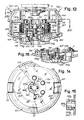
- a housing for accommodating the internal members of the apparatus comprises a first, upper cap member 1 and a second, lower cap member 3 which are the two main external components of the apparatus; the cap member 1 has on its perimeter a cylindrical wall 1A, in which are formed longitudinal seats to accommodate slides 5 which form the seats for exit and for sliding of the cords F for the cutting of the grass through the effect of the rapid rotation of the apparatus.
- the cap member 1 of the housing engages a large pin 7 with a threaded axial cavity 9 for engagement on a rotating terminal S supported by the maneuvering shaft of the grass-cutting apparatus itself; the pin 7 ends in a threaded part 7A, to which a locking screw 10 (see also Fig. 12) with a retaining head 10A can be screwed; the screw 10 is in reality a cylindrical body with a threaded cavity to accommodate the threaded portion 7A of the pin 7.
- the seat for the pin 7 is formed in part in a central internal projection 1B of the cap member 1, which is surrounded by a circumferential series of receptacles 14 of two members of a coupling.
- the cap member 1 forms a support base 1 C for a reel or bobbin 16 for the cord F.
- This bobbin 16 (see in particular Fig. 3 also) has centrally in the hub 16A a wide cylindrical hole 18, in the wall of which two series of teeth 20 and 22 are formed; the teeth 20 are developed from the upper edge to approximately half the height of the hole 18 and the teeth 22 are developed in the lower half of the wall of the hole 18; the teeth 20 and 22 are angularly staggered in relation to one another in such a manner that the teeth 20 are situated halfway in the interspace between the teeth 22 and vice-versa; the teeth project relatively little.
- the wings of the bobbin 16 can be passed through by radial slots of different depths.
- the lower cap member 3 is shaped with a wide lower circular depression 3A, from the bottom of which extends a hollow cylindrical portion 3B which ends in a bottom 3C; from this bottom, an internal cylindrical wall 3E with a bottom 3F is subsequently developed; the wall 3E with the bottom 3F is developed inside the cavity delimited by the cylindrical wall 3B.
- this wall 3B one or more (three in the drawing) longitudinal slots 26 are formed, which are subsequently developed in the bottom of the depression 3A also.
- studs 28 are developed with an arrangement, on the rim, corresponding to that of the seats 14, into which the studs 28 can penetrate.
- the axial coupling arrangement can also be inverted or varied.
- the bottom 3F is reached by the pin 7, against the offset of which it can butt, and said bottom 3F is passed through by the screw 10 and by the threaded extension 7B of said pin 7.
- the maneuvering disk 30 indicates a maneuvering disk (see also Fig. 11) which can be accommodated partially in the lower depression 3A of the lower cap member 3.
- the maneuvering disk 30 has centrally an internal core 30A which is passed through by a hole 32 which narrows in the innermost section into 32A, creating a ledge 32B between the two diameters of said hole.
- the hole 32 is passed through by the screw 10, the head 10A of which can butt against said ledge or offset 32B.
- the core 30A of the disk 30 can perform an excursion, along the cylindrical wall of the screw 10, between the head 10A of the screw and the bottom 3F.
- a sleeve 34 is provided, which has, at its perimeter on the upper edge, projecting entrainment teeth 36 in a number corresponding to that of the slots 26, which said entrainment teeth 36 can pass into and slide in, projecting outside the cylindrical wall 3B.
- the sleeve 34 has at the bottom an internal annular ledge 34A and a shoulder 34B which defines a circular passage which is capable of accommodating the core 30A of the maneuvering disk 30.
- 38 indicates a helical spring which is mounted around the wall 3E of the cap member 3 and which reacts and rests both on the bottom 3C of the member 3 and on the ledge 34A of the sleeve 34, tending to distance them axially from one another.
- the sleeve 34 and the disk 30 form an axially movable element which is stressed downwards by the spring 38.
- the lower cap member 3 When assembly has taken place, the lower cap member 3 is supported against the edge of the wall 1A of the upper cap member 1 through the effect of the elastic action of the spring 38.
- the pin 7 incorporated in the upper cap member 1 is engaged at the bottom by the screw 10, 10A which thus holds the disk 30 stressed by means of the sleeve 34 to rest on the head 10A through the effect of the spring 38;
- the sleeve 34 is supported inside the disk 30, being centered by the core 30A of said disk, and is guided within the cylindrical wall 3B of the cap member 3; this cap member 3, by means of the cylindrical wall 3E, is guided slidably on the core 1 B of the upper cap member 1.
- the spring 38 reacts on the ledge 34A of the sleeve 34 which is stabilized by the support of the sleeve 34 on the disk 30 and of the disk 30 on the head 10A of the screw 10; the spring 38 therefore stresses the cap member 3 upwards until said member rests on the edge of the wall 1A.
- the studs 28 are accommodated in the seats 14 in such a manner that there is an angular engagement between the cap members 1 and 3.
- the entrainment teeth 36 of the sleeve 34 engage both in the slots 26 and in the teeth 22 (see Fig. 6 in particular), thus ensuring the angular coupling between the bobbin 16 and the lower cap member 3; this latter is rotationally engaged with the studs 28 on the upper cap member 1.
- the lengthening of the cords F can also be carried out in another manner and in particular also during the rotation of the assembly contained in the cap members 1, 3, that is to say without stopping the grass-cutter.
- the relative angular movement of the bobbin 16 is interrupted when the teeth 36 come to rest against the teeth of the upper series 20 of the bobbin 16; there is thus a first angular advance which is equal to half the angle A indicated in Fig. 2.
- the spring 38 brings the disk 30 back until it rests against the head 10A of the screw 10; the entrainment teeth 36 thus slide in the slots 26 and return to the level of the teeth 22; under these conditions, there is a second relative angular advance of the bobbin 16 in relation to the rotating assembly 1, 3 and this therefore completes the angular excursion A, by which the bobbin 16 is made to advance, with the corresponding unrolling of the cords F, each time the assembly is pressed with the disk 30 against the ground for its penetration into the depression 3A, and the subsequent raising of it again.
- Figs 13 to 15 a solution is shown, which is modified in relation to that described above, for the adaptation of the invention to another embodiment of the assembly contained in the cap members of a grass-cutter.
- the members corresponding to the preceding embodiment are indicated by the same references increased by "100”, whereas modified parts are briefly described below.
- a coupling between the two cap members 101 and 103 is provided by means of a bayonet assembly which comprises a core 201 provided with radial studs, which is engaged on the screw 110 and which can be accommodated in two seats 203A of a receptacle 203B formed by a plate 203; said plate 203 is integral with a cylindrical wall 205, having a function similar to that of the cylindrical shell 5 in the preceding example.
- the plate 203 is provided with holes 114 which have the function of the seats 14 in the preceding example, to interact with the studs 128 formed after all by the lower cap member 103 in the manner already described.
- the plate member 203, 205 is coupled to the upper cap member 101 by means of elastic extensions 207 which are formed from the shell 205 in the area of openings 209 in the plate member 203; the elastic extensions 207 form engagement teeth in the area of openings 211 which are provided in the cap member 101 for the snap-engagement and for the release by means of pressure according to the arrows f207 exerted on the end parts of the elastic extensions 207; by means of this pressure and therefore by means of the yielding of the elastic extensions 207 towards the inside, it is possible to release from the cap member 101 the component formed by the plate 203 and by the cylindrical wall 205, from which the extensions 207 originate.
- the screw member 10 or 110 can be maneuvered with a tool for dismantling and assembly.
- said screw member be made in order to be restrained on the disk 30 or 130 angularly but slidably in an axial direction, as a result of which it is possible to effect the maneuver by means of easy manual action on said disk.
- Fig. 16 an embodiment of this type is shown, with references increased by "300" for the equivalent components to those of the first example.
- the disk 330 has a continuous lower wall and a non-circular, for example hexagonal, internal cavity 332 for axial sliding; in this cavity, the head 310A (correspondingly shaped, for example hexagonal) of the screw member 210, equivalent to 10 or 110, engages angularly but in an axially slidable manner; said head 310A is restrained in the cavity 332 for sliding by a retaining ring 333 or similar.
- the screw 310 can thus be maneuvered by means of the disk 330 which projects from the depression 303A of the cap member 303.
- the continuous closure of the disk impedes the penetration of dirt and earth to the screw 10 or 110.
- Modified embodiments of the device are possible. For example, it would be possible to exclude the maneuver of uncoupling and of manual rotation between the two cap members 1 and 3 or 101 and 103, by omitting the studs 28 or 128 and the seats 14 or 114, and therefore providing only the angular movement of the bobbin of the cords through the effect of the pressure of the disk 30 or 130 on the ground during setting in rotation.
- the sleeve 34 will have teeth 36 on two levels, in order to operate at the level of each bobbin which has the two series of teeth 20, 22.
- Figs. 17 to 20 show a modified embodiment, wherein a similar mechanism for lengthening of the cords is used in combination with a remote-control means.
- the device comprises a housing constituted by a first, lower cap member 401 and a second, upper cap member 403, which are the two main external components of the apparatus; the cap member 403 has on its perimeter a cylindrical wall 403A, in which seats are formed to accommodate bushes 405 which form the passages for the exit and the sliding of the cords F for cutting.
- the cap member 403 engages a large pin 407 with a threaded end portion 409 which is capable of engaging on a rotating terminal S supported by the maneuvering shaft A of the grass-cutting device.
- the pin 407 ends in a portion 407A which has a threaded axial hole, into which a locking screw 410 can be screwed.
- the cap member 401 has a bottom portion 401 C, on which rests the lower bobbin 416X of a pair of bobbins 416X, 416Y, on which lengths of cutting cord F are rolled up.
- Each bobbin 416X, 416Y has centrally in the hub 416A a wide cylindrical hole 418, in the wall of which two series of teeth 420 and 422 are formed.
- the teeth 420 are developed from the upper edge to approximately half the height of the hole 418 and the teeth 422 are developed in the lower half of the wall of the hole 418.
- the teeth 420 and 422 are angularly staggered in relation to one another in such a manner that the teeth 420 are situated halfway in the interspace between the teeth 422 and vice-versa.
- the teeth project relatively little.
- the wings of the bobbin can be passed through by radial slots of different depths.
- the upper cap member 403 is shaped with a wide upper depression 403X defined by a cylindrical wall 403B, in an intermediate section of which a transverse wall 403C is arranged. From this transverse wall, a prismatic wall 403E of hexagonal cross-section, and a collar 403F, is subsequently developed. In the cylindrical wall 403B, one or more (three in the drawing) longitudinal slots 426 are formed, which are developed over the entire length of the cylindrical wall 403B.
- the pin 407 passes through the transverse wall 403C and axially through the prismatic wall 403E and the collar 403F.
- the upper cap member 403 is locked on the pin 407 in an axial direction by means of a shoulder formed on the pin itself by a hexagonal prismatic portion 407B and by an elastic ring.
- the form coupling provided by the hexagonal prismatic portion 407B and by the prismatic wall 403E makes it possible to rotate the upper cap member 403 jointly with the pin 407.
- the maneuvering disk 430 indicates a maneuvering disk which projects above the upper cap member 403.
- the maneuvering disk 430 is supported idle on the pin 407 by means of a bearing 431.
- the maneuvering disk 430 can perform an axial excursion along the pin 407 under the control of suitable operating means.
- the support bearing 431 of the maneuvering disk is mounted on a collar 432 of a small disk 434 which bears a plurality (three in the example of the drawing) of extensions 435.
- the extensions 435 are made separately from the small disk 434 and are mounted on the latter by jointing.
- Each extension 435 is provided with a pair of entrainment teeth 436 which project through the longitudinal slots 426 made in the cylindrical wall 403B and are slidable along these.
- the longitudinal sliding movement of the entrainment teeth 436 along the slots 426 is achieved by means of the axial movement of the small disk 434 along the axis of the pin 407 in the manner described below.
- the extensions 435 bearing the entrainment teeth 436 are guided by guide channels 437 made on the cylindrical wall 403B parallel to the longitudinal slots 426 on both sides of these (see Fig. 19 in particular).
- the number of bobbins can be different from that illustrated, for example one single bobbin can be provided or more than two bobbins also. More than one cord can also be rolled up on each bobbin. In each case, the corresponding number of entrainment teeth 436 is to be provided on each extension 435.
- the lower cap member 401 When assembly has taken place, the lower cap member 401 is supported against the edge of the wall 403A of the upper cap member 403 and is gripped by means of the screw 410. The relative rotation between lower cap member 401 arid upper cap member 403 is prevented by a series of extensions 401 C which are integral with the lower cap member 401 and which are inserted between adjacent channels 437 of the cylindrical wall 403B of the upper cap member 403. In the rest position, the disk 430 is maintained in its position of maximum distance from the cap member 403 through the effect of the spring 438, said position being defined by an elastic ring 439 on the pin 407.
- the entrainment teeth 436 are situated in the area of the upper teeth 420 of each of the two bobbins 416X and 416Y of cord, providing an angular coupling between said bobbins and the housing formed by the two cap members 401 and 403.
- a protection housing 450 is arranged, which is supported by means of a bearing 452 on the pin 407.
- the protection casing 450 is restrained on the maneuvering shaft A of the trimmer by means of an inverted U-shaped bracket 454.
- a pulley 456 is supported, on which a cable 458 is directed, which serves to remote control the lengthening of the cords F.
- One end of the cable 458 is anchored on a control ring 460 which is coaxial with the pin 407 and slidable in an axial direction in relation to it.
- the axial movement of the control ring 460 is guided by means of a pair of guides 462 which are made inside the protection casing 450.
- control ring 460 In rest position (Fig. 17), the control ring 460 is maintained in its upper position - that is to say at maximum distance from the maneuvering disk 430 underneath - by a compression spring 464 which reacts between the control ring 460 and a pair of support brackets 466 of the pulley 456.
- the control ring 460 assumes the position shown in Fig. 18. During its downward stroke, the control ring 460 comes into contact with the upper surface of the maneuvering disk 430, causing it to move downwards against the action of the counteractive spring 438. Since the maneuvering disk 430 is mounted idle by means of the interposition of the bearing 431, when the control ring 460 comes into contact with the maneuvering disk 430, the latter stops rotating in relation to the protection casing, so that there is no relative movement between control ring 460 and maneuvering disk 430. At the same time, by virtue of the bearing 431, the small disk 434 remains free to rotate jointly with the housing formed by the cap members 401 and 403.
- the downward movement of the maneuvering disk 430 causes an axial sliding of the small disk 434 along the pin 407. This movement causes a sliding of the entrainment teeth 436 along the slots 426 and therefore the release of the entrainment teeth from the upper teeth 420 of the two bobbins 416X and 416Y.
- the maneuvering disk 430 is mounted by means of a bearing in order to avoid relative sliding between said disk and the control ring 460.
- suitable materials for example one of synthetic resin and the other of metal
- Figs. 21 to 23 show an embodiment similar to that of Figs. 1 to 16. Similar or corresponding parts are indicated with the same reference numbers.
- the device of Fig. 21 is provided with a disk 50 (having the same functions as disk 30), which is part of the sliding element 34, 50.
- a cover 52 forms, in combination with disk 50, a housing for a set of balls 56 which are retained between inclined rolling surfaces 54 and the planar lower surface of disk 50.
- the balls 56 are maintained by the action of spring 38 in the position of Fig. 21, i.e. close to the rotation axis of the device.
- the device shown in Figs. 21 to 23 is able to operate in three different ways, namely:
- the two caps 1, 3 could be solid to each other, so that mode (c) is not available, and/or by engaging the cover 52 firmly to the cap 3, so that mode (b) (or (b) and (c)) are not available, and the device operates only automatically.
- Fig. 24 shows a device similar to the device of Figs. 17 to 20. Same or corresponding elements are indicated with the same reference numbers.
- the small disk 434 is provided with inclinated rolling surfaces 474 on which balls 476 can roll. Balls 476 are housed between said inclined rolling surfaces 474 and disk 451 which is fitted on the pin 407, between the small disk 434 and the bearing 431.
- the bearing 431 supports a disk 453 which is similar to disk 430 of Fig. 17 and which is suitable to cooperate with the ring 460.
- the device of Fig. 24 operates in the same way as the device of Figs. 17 to 20, but has a further possibility of an automatic mode of operation, similar to the one described with reference to Figs. 21 to 23.
- Pay-out of the cords can be performed either manually acting with ring 460 as above described with reference to Figs. 17 to 20, or automatically due to the centrifugal force acting on balls 456.
- the rotational speed of the device exceeds a certain value, determined by the inclination of surfaces 474, the force of spring 438 and the mass of balls 476, due to the wear of the cords, the balls 476 are moved radially outwardly by the centrifugal force.
- the device of Fig. 24 could work also only in the automatic mode by omitting ring 460 and cable 458. In this case the pay-out of cords F is obtained by way of centrifugal force only. It should also be noted that in this case the disk 451 could form a cover casing and the casing 450 could be omitted.
- rollers which could be hollow, in order to reduce the mass of the roller. This could be advantageous when choosing the value of the mass of the rollers and the force of the spring 438 in order to set an optimum value of the rotational speed for which automatic pay-out of the cords is obtained.
Landscapes
- Life Sciences & Earth Sciences (AREA)
- Environmental Sciences (AREA)
- Harvester Elements (AREA)
- Knitting Machines (AREA)
Applications Claiming Priority (4)
| Application Number | Priority Date | Filing Date | Title |
|---|---|---|---|
| IT9554A IT1236082B (it) | 1989-10-30 | 1989-10-30 | Congegno per l'avanzamento radiale centrifugo dei fili dalle teste tagliaerba per decespugliatori ed altro |
| IT9451A IT1241759B (it) | 1990-07-19 | 1990-07-19 | Dispositivo tagliaerba per decespugliatore con congegno di allungamento dei fili di taglio. |
| IT945190 | 1990-07-19 | ||
| IT955489 | 1990-10-30 |
Publications (2)
| Publication Number | Publication Date |
|---|---|
| EP0467006A1 true EP0467006A1 (fr) | 1992-01-22 |
| EP0467006B1 EP0467006B1 (fr) | 1995-01-18 |
Family
ID=26326221
Family Applications (1)
| Application Number | Title | Priority Date | Filing Date |
|---|---|---|---|
| EP90830458A Expired - Lifetime EP0467006B1 (fr) | 1989-10-30 | 1990-10-16 | Appareil pour l'alimentation radiale centrifuge des fils de la tête de coupe pour tondeuse à filament ou similaire |
Country Status (8)
| Country | Link |
|---|---|
| US (1) | US5095688A (fr) |
| EP (1) | EP0467006B1 (fr) |
| JP (1) | JP2948895B2 (fr) |
| AT (1) | ATE117165T1 (fr) |
| AU (1) | AU640420B2 (fr) |
| CA (1) | CA2028034C (fr) |
| DE (1) | DE69016201T2 (fr) |
| ES (1) | ES2067016T3 (fr) |
Cited By (5)
| Publication number | Priority date | Publication date | Assignee | Title |
|---|---|---|---|---|
| EP0641512A3 (fr) * | 1990-11-16 | 1995-04-19 | Diatop Corp | Tête de coupe pour tondeuse à filament. |
| EP0970596A3 (fr) * | 1998-07-07 | 2000-06-21 | Arnetoli Motor Di Arnetoli Fabrizio | Tête de coupe à rechargement de filament sans retrait de la bobine |
| EP1479277A1 (fr) * | 2003-05-20 | 2004-11-24 | Donald Joe Sullivan | Adaptateur pour désherbeur |
| ITRM20080649A1 (it) * | 2008-12-04 | 2010-06-05 | Agostino Salvatore D | Decespugliatore |
| SE1850147A1 (en) * | 2018-02-12 | 2019-08-13 | Husqvarna Ab | Trimmer head and trimmer |
Families Citing this family (27)
| Publication number | Priority date | Publication date | Assignee | Title |
|---|---|---|---|---|
| US5311665A (en) * | 1990-11-16 | 1994-05-17 | Diatop Corporation | Cutting head for a cord type mower |
| US5345683A (en) * | 1991-01-14 | 1994-09-13 | Takahiro Kanou | Rotary cutter for mowing machine |
| DE4227487A1 (de) * | 1992-08-20 | 1994-02-24 | Gardena Kress & Kastner Gmbh | Trenngerät, insbesondere Fadenschneider |
| US5365724A (en) * | 1993-04-06 | 1994-11-22 | Country Home Products, Inc. | Anti-wrap device for rotating shaft |
| US5339526A (en) * | 1993-04-22 | 1994-08-23 | Ryobi Outdoor Products | Resistance spool for a line trimmer head |
| WO1995006402A1 (fr) * | 1993-08-30 | 1995-03-09 | Alan Wesley Talbot | Fil de coupe pour tondeuse |
| JP3167859B2 (ja) * | 1994-04-07 | 2001-05-21 | タナカ工業株式会社 | ナイロンコード型刈払機 |
| US5743019A (en) * | 1995-06-07 | 1998-04-28 | Berfield; Robert C. | Rotary flail feeding device and method |
| US5675897A (en) * | 1996-05-01 | 1997-10-14 | Berfield; Robert C. | Rotary flail feeding device |
| IT1294822B1 (it) | 1997-07-18 | 1999-04-15 | Arnetoli Motor | Testina taglia-erba a filo com mezzi per prevenire l'ingresso di detriti |
| US5906051A (en) * | 1998-04-03 | 1999-05-25 | Nannen; William G. | Height adjustable anti-gouging ground guide system for vegetation trimmer |
| IT1314465B1 (it) | 2000-01-04 | 2002-12-18 | Arnetoli Motor | Rocchetto per l'avvolgimento di un filo di taglio per un tagliaerba e testina per tagliaerba incorporante detto rocchetto |
| US6385853B1 (en) | 2000-06-26 | 2002-05-14 | Robert C. Berfield | Rotary flail feeding device |
| US6971223B2 (en) * | 2001-01-25 | 2005-12-06 | Electrolux Home Products, Inc. | Wheeled trimmer device of adjustable height |
| ITFI20050192A1 (it) | 2005-09-13 | 2007-03-14 | Arnetoli Motor | Testina tosaerba con mezzi per la protezione del filo di taglio |
| EP1942717B1 (fr) * | 2005-11-02 | 2009-10-21 | Fabrizio Arnetoli | Tete de coupe d'herbe avec des canaux de guidage en spirale pour la ligne de coupe |
| JP2008263854A (ja) * | 2007-04-20 | 2008-11-06 | Isao Kohama | 草刈り・稲刈り用の刃物台 |
| JP4999190B2 (ja) * | 2008-07-25 | 2012-08-15 | スターテング工業株式会社 | 刈払い機用ロータリカッタ |
| US8567073B2 (en) * | 2010-03-04 | 2013-10-29 | Proulx Manufacturing, Inc. | Aerodynamic trimmer head for use in flexible line rotary trimmers |
| US9253942B2 (en) * | 2010-09-20 | 2016-02-09 | George E. Alliss | Trimmer head with automatic trimmer line feed mechanism |
| CN104221578B (zh) * | 2013-06-09 | 2017-11-07 | 南京德朔实业有限公司 | 打草机及其打草头 |
| PL3056075T3 (pl) * | 2015-02-16 | 2017-10-31 | Tecomec Srl | Automatyczna głowica przycinarki |
| CN109691318B (zh) * | 2017-10-20 | 2021-06-18 | 南京德朔实业有限公司 | 打草头和用于打草的工具系统 |
| EP3785518B1 (fr) * | 2019-08-30 | 2023-07-05 | Andreas Stihl AG & Co. KG | Tête de faucheuse à monter sur un arbre d'entraînement d'une débroussailleuse |
| WO2021070251A1 (fr) * | 2019-10-08 | 2021-04-15 | 株式会社北村製作所 | Corps rotatif, débrousailleuse et bobine |
| CN115250721B (zh) * | 2022-08-25 | 2026-04-17 | 浙江动一新能源动力科技股份有限公司 | 打草头、作业头以及打草机 |
| JP7217485B1 (ja) * | 2022-10-30 | 2023-02-03 | 有限会社とまと不動産 | 刈払機に取り付け可能なコードリールカセット及びそれを備える刈払機 |
Citations (9)
| Publication number | Priority date | Publication date | Assignee | Title |
|---|---|---|---|---|
| US4134204A (en) * | 1976-06-01 | 1979-01-16 | Perdue Bennie G | Rotary flail cutter system |
| US4209902A (en) * | 1977-12-19 | 1980-07-01 | Emerson Electric Co. | Apparatus for cutting vegetation |
| DE3005968A1 (de) * | 1980-02-16 | 1981-08-20 | Gardena Kress + Kastner Gmbh, 7900 Ulm | Fadenschneider |
| EP0140634A1 (fr) * | 1983-10-15 | 1985-05-08 | Tanaka Kogyo K.K. | Appareil de coupe à filament |
| WO1985004548A1 (fr) * | 1984-04-09 | 1985-10-24 | Wolf-Geräte Gmbh | Tete de coupe pour coupe-fil |
| US4561180A (en) * | 1984-06-29 | 1985-12-31 | Pittinger Sr Charles B | Apparatus for cutting vegetation with incremental feeding of cutting filament |
| EP0249585A1 (fr) * | 1986-06-13 | 1987-12-16 | Maria Rosa Calcinai | Tondeuse à gazon et à buisson munie d'un dispositif de dévidage du fil de coupe |
| US4790071A (en) * | 1987-01-02 | 1988-12-13 | Trimrite, Inc. | Line trimmer with replaceable cutting blade assembly |
| EP0315603A1 (fr) * | 1987-11-04 | 1989-05-10 | Maria Rosa Calcinai | Appareil de coupe à filament |
Family Cites Families (4)
| Publication number | Priority date | Publication date | Assignee | Title |
|---|---|---|---|---|
| US4242797A (en) * | 1979-06-28 | 1981-01-06 | Palmieri Vincent A | Rotary nylon line vegetation cutter |
| US4823465A (en) * | 1986-12-17 | 1989-04-25 | White Consolidated Industries, Inc. | Line feed mechanism for line trimmers |
| JPH0620351Y2 (ja) * | 1987-06-11 | 1994-06-01 | 株式会社共立 | 可撓性フイラメント式草刈機のヘツド構造 |
| DE3739269A1 (de) * | 1987-11-20 | 1989-06-01 | Stihl Maschf Andreas | Schneidkopf |
-
1990
- 1990-10-16 EP EP90830458A patent/EP0467006B1/fr not_active Expired - Lifetime
- 1990-10-16 DE DE69016201T patent/DE69016201T2/de not_active Expired - Lifetime
- 1990-10-16 AT AT90830458T patent/ATE117165T1/de not_active IP Right Cessation
- 1990-10-16 ES ES90830458T patent/ES2067016T3/es not_active Expired - Lifetime
- 1990-10-19 CA CA002028034A patent/CA2028034C/fr not_active Expired - Fee Related
- 1990-10-26 US US07/605,227 patent/US5095688A/en not_active Expired - Lifetime
- 1990-10-29 AU AU65553/90A patent/AU640420B2/en not_active Ceased
- 1990-10-30 JP JP2290970A patent/JP2948895B2/ja not_active Expired - Fee Related
Patent Citations (9)
| Publication number | Priority date | Publication date | Assignee | Title |
|---|---|---|---|---|
| US4134204A (en) * | 1976-06-01 | 1979-01-16 | Perdue Bennie G | Rotary flail cutter system |
| US4209902A (en) * | 1977-12-19 | 1980-07-01 | Emerson Electric Co. | Apparatus for cutting vegetation |
| DE3005968A1 (de) * | 1980-02-16 | 1981-08-20 | Gardena Kress + Kastner Gmbh, 7900 Ulm | Fadenschneider |
| EP0140634A1 (fr) * | 1983-10-15 | 1985-05-08 | Tanaka Kogyo K.K. | Appareil de coupe à filament |
| WO1985004548A1 (fr) * | 1984-04-09 | 1985-10-24 | Wolf-Geräte Gmbh | Tete de coupe pour coupe-fil |
| US4561180A (en) * | 1984-06-29 | 1985-12-31 | Pittinger Sr Charles B | Apparatus for cutting vegetation with incremental feeding of cutting filament |
| EP0249585A1 (fr) * | 1986-06-13 | 1987-12-16 | Maria Rosa Calcinai | Tondeuse à gazon et à buisson munie d'un dispositif de dévidage du fil de coupe |
| US4790071A (en) * | 1987-01-02 | 1988-12-13 | Trimrite, Inc. | Line trimmer with replaceable cutting blade assembly |
| EP0315603A1 (fr) * | 1987-11-04 | 1989-05-10 | Maria Rosa Calcinai | Appareil de coupe à filament |
Cited By (7)
| Publication number | Priority date | Publication date | Assignee | Title |
|---|---|---|---|---|
| EP0641512A3 (fr) * | 1990-11-16 | 1995-04-19 | Diatop Corp | Tête de coupe pour tondeuse à filament. |
| EP0970596A3 (fr) * | 1998-07-07 | 2000-06-21 | Arnetoli Motor Di Arnetoli Fabrizio | Tête de coupe à rechargement de filament sans retrait de la bobine |
| US6944954B1 (en) | 1998-07-07 | 2005-09-20 | Arnetoli Motor Di Arnetoli Fabrizio | Grass-cutting head with reloading of the line without removal of the spool |
| EP1479277A1 (fr) * | 2003-05-20 | 2004-11-24 | Donald Joe Sullivan | Adaptateur pour désherbeur |
| ITRM20080649A1 (it) * | 2008-12-04 | 2010-06-05 | Agostino Salvatore D | Decespugliatore |
| SE1850147A1 (en) * | 2018-02-12 | 2019-08-13 | Husqvarna Ab | Trimmer head and trimmer |
| US12114596B2 (en) | 2018-02-12 | 2024-10-15 | Husqvarna Ab | Trimmer head and trimmer |
Also Published As
| Publication number | Publication date |
|---|---|
| JP2948895B2 (ja) | 1999-09-13 |
| CA2028034C (fr) | 2001-02-27 |
| US5095688A (en) | 1992-03-17 |
| AU640420B2 (en) | 1993-08-26 |
| CA2028034A1 (fr) | 1991-05-01 |
| EP0467006B1 (fr) | 1995-01-18 |
| DE69016201T2 (de) | 1995-07-20 |
| JPH03160917A (ja) | 1991-07-10 |
| ES2067016T3 (es) | 1995-03-16 |
| ATE117165T1 (de) | 1995-02-15 |
| DE69016201D1 (de) | 1995-03-02 |
| AU6555390A (en) | 1991-05-02 |
Similar Documents
| Publication | Publication Date | Title |
|---|---|---|
| EP0467006B1 (fr) | Appareil pour l'alimentation radiale centrifuge des fils de la tête de coupe pour tondeuse à filament ou similaire | |
| EP1670305B1 (fr) | Tete pour coupe-gazon rotatifs a fil souple | |
| EP0970596B1 (fr) | Tête de coupe à rechargement de filament sans retrait de la bobine | |
| US4660286A (en) | Apparatus with automatic line feeding | |
| US4702005A (en) | Apparatus for cutting vegetation with incremental feeding of cutting filament | |
| US4566189A (en) | Filament-type trimming apparatus | |
| EP0560926B1 (fr) | Tete automatique de tondeuse a fil | |
| CA2245580C (fr) | Configuration du mecanisme d'amenee du fil pour tondeuse a fil | |
| US4882843A (en) | Structure of a head of a flexible filament type grass trimmer | |
| US20180279547A1 (en) | Spool assembly for a trimmer head | |
| EP1795062A2 (fr) | Tête de coupe à chargement rapide pour coupeuse rotative | |
| US4561180A (en) | Apparatus for cutting vegetation with incremental feeding of cutting filament | |
| US4236309A (en) | Flexible line trimmer with line feeding apparatus | |
| KR950005779B1 (ko) | 라인절단기의 헤드조립체 | |
| CA1290152C (fr) | Coupe gagon et buisson avec dispositif a distance pour sectimner le cable de coupe | |
| US20260096506A1 (en) | Power tool and compact power feed trimmer head | |
| DE3751807T2 (de) | Vorrichtung zum Schneiden von Pflanzen | |
| JPS6033788Y2 (ja) | 刈払機 | |
| CA1212552A (fr) | Taille-bordures fouettant a reserve de fil | |
| CN118489401A (zh) | 动力工具和紧凑型动力进给修剪机头 | |
| CA1125522A (fr) | Coupe-bordure a reserve de filament | |
| IT9009488A1 (it) | Dispositivo tagliaerba per decespugliatore con congegno automatico di allungamento dei fili di taglio | |
| DE1660949A1 (de) | Spulvorrichtung fuer die Unterfadenspule einer Naehmaschine | |
| IT9009451A1 (it) | Dispositivo tagliaerba per decespugliatore con congegno di allungamento dei fili di taglio. |
Legal Events
| Date | Code | Title | Description |
|---|---|---|---|
| PUAI | Public reference made under article 153(3) epc to a published international application that has entered the european phase |
Free format text: ORIGINAL CODE: 0009012 |
|
| AK | Designated contracting states |
Kind code of ref document: A1 Designated state(s): AT BE CH DE ES FR GB LI NL |
|
| 17P | Request for examination filed |
Effective date: 19911218 |
|
| 17Q | First examination report despatched |
Effective date: 19930802 |
|
| GRAA | (expected) grant |
Free format text: ORIGINAL CODE: 0009210 |
|
| AK | Designated contracting states |
Kind code of ref document: B1 Designated state(s): AT BE CH DE ES FR GB LI NL |
|
| REF | Corresponds to: |
Ref document number: 117165 Country of ref document: AT Date of ref document: 19950215 Kind code of ref document: T |
|
| REF | Corresponds to: |
Ref document number: 69016201 Country of ref document: DE Date of ref document: 19950302 |
|
| REG | Reference to a national code |
Ref country code: ES Ref legal event code: FG2A Ref document number: 2067016 Country of ref document: ES Kind code of ref document: T3 |
|
| ET | Fr: translation filed | ||
| PLBE | No opposition filed within time limit |
Free format text: ORIGINAL CODE: 0009261 |
|
| STAA | Information on the status of an ep patent application or granted ep patent |
Free format text: STATUS: NO OPPOSITION FILED WITHIN TIME LIMIT |
|
| 26N | No opposition filed | ||
| REG | Reference to a national code |
Ref country code: GB Ref legal event code: IF02 |
|
| PGFP | Annual fee paid to national office [announced via postgrant information from national office to epo] |
Ref country code: AT Payment date: 20040929 Year of fee payment: 15 |
|
| PG25 | Lapsed in a contracting state [announced via postgrant information from national office to epo] |
Ref country code: AT Free format text: LAPSE BECAUSE OF NON-PAYMENT OF DUE FEES Effective date: 20051016 |
|
| PGFP | Annual fee paid to national office [announced via postgrant information from national office to epo] |
Ref country code: NL Payment date: 20051028 Year of fee payment: 16 |
|
| PGFP | Annual fee paid to national office [announced via postgrant information from national office to epo] |
Ref country code: ES Payment date: 20061011 Year of fee payment: 17 Ref country code: GB Payment date: 20061011 Year of fee payment: 17 |
|
| PGFP | Annual fee paid to national office [announced via postgrant information from national office to epo] |
Ref country code: CH Payment date: 20070112 Year of fee payment: 17 |
|
| PG25 | Lapsed in a contracting state [announced via postgrant information from national office to epo] |
Ref country code: NL Free format text: LAPSE BECAUSE OF NON-PAYMENT OF DUE FEES Effective date: 20070501 |
|
| NLV4 | Nl: lapsed or anulled due to non-payment of the annual fee |
Effective date: 20070501 |
|
| GBPC | Gb: european patent ceased through non-payment of renewal fee |
Effective date: 20071016 |
|
| REG | Reference to a national code |
Ref country code: CH Ref legal event code: PL |
|
| PG25 | Lapsed in a contracting state [announced via postgrant information from national office to epo] |
Ref country code: LI Free format text: LAPSE BECAUSE OF NON-PAYMENT OF DUE FEES Effective date: 20071031 Ref country code: CH Free format text: LAPSE BECAUSE OF NON-PAYMENT OF DUE FEES Effective date: 20071031 |
|
| PG25 | Lapsed in a contracting state [announced via postgrant information from national office to epo] |
Ref country code: GB Free format text: LAPSE BECAUSE OF NON-PAYMENT OF DUE FEES Effective date: 20071016 |
|
| REG | Reference to a national code |
Ref country code: ES Ref legal event code: FD2A Effective date: 20071017 |
|
| PG25 | Lapsed in a contracting state [announced via postgrant information from national office to epo] |
Ref country code: ES Free format text: LAPSE BECAUSE OF NON-PAYMENT OF DUE FEES Effective date: 20071017 |
|
| PGFP | Annual fee paid to national office [announced via postgrant information from national office to epo] |
Ref country code: DE Payment date: 20091204 Year of fee payment: 20 |
|
| PGFP | Annual fee paid to national office [announced via postgrant information from national office to epo] |
Ref country code: FR Payment date: 20091117 Year of fee payment: 20 |
|
| PGFP | Annual fee paid to national office [announced via postgrant information from national office to epo] |
Ref country code: BE Payment date: 20091130 Year of fee payment: 20 |
|
| BE20 | Be: patent expired |
Owner name: *ARNETOLI MOTOR DI ARNETOLI FABRIZIO Effective date: 20101016 |
|
| PG25 | Lapsed in a contracting state [announced via postgrant information from national office to epo] |
Ref country code: DE Free format text: LAPSE BECAUSE OF EXPIRATION OF PROTECTION Effective date: 20101016 |