EP0466542A1 - Cylinder block for an engine comprising a carter vapour evacuation and oil recycling circuit - Google Patents
Cylinder block for an engine comprising a carter vapour evacuation and oil recycling circuit Download PDFInfo
- Publication number
- EP0466542A1 EP0466542A1 EP91401710A EP91401710A EP0466542A1 EP 0466542 A1 EP0466542 A1 EP 0466542A1 EP 91401710 A EP91401710 A EP 91401710A EP 91401710 A EP91401710 A EP 91401710A EP 0466542 A1 EP0466542 A1 EP 0466542A1
- Authority
- EP
- European Patent Office
- Prior art keywords
- casing
- conduits
- chamber
- circuit
- internal
- Prior art date
- Legal status (The legal status is an assumption and is not a legal conclusion. Google has not performed a legal analysis and makes no representation as to the accuracy of the status listed.)
- Granted
Links
Images


Classifications
-
- F—MECHANICAL ENGINEERING; LIGHTING; HEATING; WEAPONS; BLASTING
- F01—MACHINES OR ENGINES IN GENERAL; ENGINE PLANTS IN GENERAL; STEAM ENGINES
- F01M—LUBRICATING OF MACHINES OR ENGINES IN GENERAL; LUBRICATING INTERNAL COMBUSTION ENGINES; CRANKCASE VENTILATING
- F01M13/00—Crankcase ventilating or breathing
-
- F—MECHANICAL ENGINEERING; LIGHTING; HEATING; WEAPONS; BLASTING
- F02—COMBUSTION ENGINES; HOT-GAS OR COMBUSTION-PRODUCT ENGINE PLANTS
- F02B—INTERNAL-COMBUSTION PISTON ENGINES; COMBUSTION ENGINES IN GENERAL
- F02B75/00—Other engines
- F02B75/16—Engines characterised by number of cylinders, e.g. single-cylinder engines
- F02B75/18—Multi-cylinder engines
- F02B75/22—Multi-cylinder engines with cylinders in V, fan, or star arrangement
-
- F—MECHANICAL ENGINEERING; LIGHTING; HEATING; WEAPONS; BLASTING
- F02—COMBUSTION ENGINES; HOT-GAS OR COMBUSTION-PRODUCT ENGINE PLANTS
- F02F—CYLINDERS, PISTONS OR CASINGS, FOR COMBUSTION ENGINES; ARRANGEMENTS OF SEALINGS IN COMBUSTION ENGINES
- F02F7/00—Casings, e.g. crankcases or frames
- F02F7/0002—Cylinder arrangements
- F02F7/0012—Crankcases of V-engines
-
- F—MECHANICAL ENGINEERING; LIGHTING; HEATING; WEAPONS; BLASTING
- F02—COMBUSTION ENGINES; HOT-GAS OR COMBUSTION-PRODUCT ENGINE PLANTS
- F02B—INTERNAL-COMBUSTION PISTON ENGINES; COMBUSTION ENGINES IN GENERAL
- F02B75/00—Other engines
- F02B75/16—Engines characterised by number of cylinders, e.g. single-cylinder engines
- F02B75/18—Multi-cylinder engines
- F02B2075/1804—Number of cylinders
- F02B2075/1824—Number of cylinders six
-
- F—MECHANICAL ENGINEERING; LIGHTING; HEATING; WEAPONS; BLASTING
- F02—COMBUSTION ENGINES; HOT-GAS OR COMBUSTION-PRODUCT ENGINE PLANTS
- F02F—CYLINDERS, PISTONS OR CASINGS, FOR COMBUSTION ENGINES; ARRANGEMENTS OF SEALINGS IN COMBUSTION ENGINES
- F02F1/00—Cylinders; Cylinder heads
- F02F1/02—Cylinders; Cylinder heads having cooling means
- F02F1/10—Cylinders; Cylinder heads having cooling means for liquid cooling
- F02F2001/104—Cylinders; Cylinder heads having cooling means for liquid cooling using an open deck, i.e. the water jacket is open at the block top face
-
- F—MECHANICAL ENGINEERING; LIGHTING; HEATING; WEAPONS; BLASTING
- F02—COMBUSTION ENGINES; HOT-GAS OR COMBUSTION-PRODUCT ENGINE PLANTS
- F02F—CYLINDERS, PISTONS OR CASINGS, FOR COMBUSTION ENGINES; ARRANGEMENTS OF SEALINGS IN COMBUSTION ENGINES
- F02F2200/00—Manufacturing
- F02F2200/06—Casting
Definitions
- the present invention relates to an upper casing or cylinder block for any internal combustion engine, for example of the V-cylinder or in-line type.
- the internal conduits of the prior art are of complex shape, and have small gas and oil passage sections.
- these conduits are obtained by machining or with the aid of foundry pins or fragile molding cores, so that the casings thus produced are expensive and insufficiently rigid.
- the object of the present invention is to remedy these drawbacks by proposing an upper casing with internal ducts for discharging the gases from the casing and for recycling the engine oil which are of simple shape. and large passage sections, and which, moreover, can be produced at a lower cost, while increasing the rigidity of the casing, thanks to the use of a unique and resistant molding core.
- the subject of the invention is an upper cylinder head casing for any internal combustion engine, such as of the V-cylinder or in-line type, and comprising internal conduits which connect the upper part of the casing to compartments separating the crankshaft bearings, these conduits allowing the evacuation of gases from the crankcase and the recycling of engine oil, this crankcase being characterized in that said internal evacuation and recycling conduits open into a flattened chamber, arranged near the lower compartments and crossed perpendicularly by the cylinders, said chamber and said internal conduits forming a circuit from the foundry.
- the invention is further characterized in that the circuit includes gas passages from the casing which connect the aforementioned chamber to each of the lower compartments.
- the upper casing is further characterized in that internal oil recycling conduits extend substantially parallel to the cylinders and respectively connect the circuit chamber to a mounting plane of a cylinder head and to an opposite lower face of the casing, these conduits being offset from each other.
- the circuit chamber has the shape of a dihedral, with a central or edge part which is connected to conduits internal extending between the two lines of cylinders and opening onto a face of the casing provided for mounting a gas treatment member of the casing.
- the invention is further characterized in that cooling chambers are formed around the cylinders for the circulation of a cooling liquid, the circuit chamber being located between the cooling chambers and the aforementioned lower compartments.
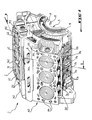
- Figure 1 is a perspective view of an upper casing according to the invention, for an internal combustion engine of the V-cylinder type.
- Figure 2 is a sectional view of the upper housing of Figure 1 and along the line II-II.
- FIG. 3 illustrates in perspective the shape of the chamber and of the internal conduits which constitute the evacuation and recycling circuit according to the invention.
- an engine M notably comprises an upper casing or cylinder block 1, a lower casing 2 and two cylinder heads 3a and 3b which are fixed to the upper cylinder head casing 1 .
- the engine M is of the type with 6 cylinders in V, that is to say comprises, on either side of a longitudinal plane XX ′ two lines of three cylinders 41 and 42. It is also noted that lower compartments 5 which separate transverse walls 11 (only one of which is visible in FIG. 1 and on FIG. 2) in which crankshaft bearings 12 are formed are produced in the upper casing 1 so as to open into a face forming a lower joint plane 13 against which the lower casing 2 is mounted.
- Each cylinder 41, 42 opens on the one hand into the upper part 143 of the casing 1 and on the other hand into one of the lower compartments 5.
- the three aligned cylinders which are designated by the reference numeral 41 are produced on one side of the longitudinal plane XX ′ and open onto a joint plane 141 of the upper part 143, on which plane the cylinder head 3a is mounted.
- the other three cylinders 42 are produced in the casing 1 on the other side of the plane X-X ′ and lead to another joint plane 142 of the upper part 143, on which plane the cylinder head 3b is mounted.
- each cylinder 41, 42 can be inserted into each cylinder 41, 42, for example during the molding of the upper casing 1.
- coolant supply conduits produced in the casing 1 and which extend substantially parallel to a longitudinal direction of the casing 1.
- the supply conduits 151 and 152 are respectively connected to cooling chambers 161 and 162 which are formed around each cylinder 41, 42, so as to allow circulation of coolant in the casing 1.
- Holes 171, 172 for communication of the cooling chambers 161 and 162 with the cylinder heads 3a and 3b open respectively in the joint planes 141 and 142.
- the coolant is introduced into the casing 1 via an opening 153 which opens into a transverse face 6 of the casing 1 and which extends substantially parallel to the transverse walls described above.
- FIG. 2 shows a longitudinal channel 173 for circulation of pressurized oil which extends in the longitudinal direction of the casing 2, along the lower compartments 5.
- the upper casing 1 also comprises internal conduits for discharging gas from the casing and for recycling the oil which will now be described, with further reference to FIG. 3.
- the upper casing 1 comprises internal pipes 7 for recycling engine oil and internal pipes 8 for evacuating the gases from the casing which open into a chamber 9, so as to form a circuit C coming from foundry with the casing 1 and shown in perspective in FIG. 3.
- the chamber 9 of the circuit C is in the form of a flattened dihedron and extends near a top wall 51 of the lower compartments 5 of the casing 1.
- the chamber 9 is therefore constituted by two flattened and contiguous parts identified at 91 and 92 Each flattened part 91 and 92 of the chamber 9 is crossed substantially at right angles by the cylinders 41 and 42, respectively.
- a central part 93 of the chamber 9 forms an edge which extends in the longitudinal direction of the casing 1, right through the chamber 9.
- Two evacuation conduits 8 of oblong section extend, between the cylinders 41, 42, from the upper part of the edge 93 to a central face 144 of the casing 1 which is provided for mounting a treatment (not shown) of the crankcase gases.
- the chamber 9 of the circuit C formed in the upper casing 1 is located between the cooling chambers 161 and 162 and the lower compartments 5.
- the recycling conduits 7 extend laterally from each free end of the flattened parts 91, 92 of the chamber 9, and consist of upper sections 7a and lower sections 7b.
- each flattened part 91, 92 of the chamber 9 comprises five upper sections 7a and three lower sections 7b, of oblong section.
- the upper sections 7a of the recycling conduits 7 are formed in the casing 1 so as to extend substantially parallel to the cylinder lines 41 and 42.
- These upper sections 7a are connected five to five, at their upper part, by channels 71 and 72 which open respectively in the joint planes 141 and 142.
- each of the channels 71 and 72 is produced near a lateral flange 241, 242 of the joint planes 141 and 142 of the housing 1, and extend in a direction substantially parallel to the longitudinal direction of the housing.
- the lower sections 7b of the recycling conduits 7 extend, from top to bottom along the side walls 52 of the compartments 5 which are parallel to the plane XX ′, from one of the flattened parts 91, 92 of the chamber 9 to the joint plane 13 against which the lower casing 2 is mounted.
- the upper sections 7a and the lower sections 7b of the recycling conduits 7 are offset from one another.
- the lower sections 7b are substantially parallel to the plane X-X ′ and therefore do not extend exactly in alignment with the upper sections 7a which are parallel to the cylinders 41, 42.
- the lower sections 7b open into the chamber 9 at locations which are not located exactly opposite the ends of the upper sections 7a which open into each flattened part 91, 92 of the chamber 9.
- Such a shift between the sections 7a and 7b makes it possible to "break" the flow of oil flow towards the lower casing 2, but also makes it possible to improve the evacuation of the gases by allowing the gases trapped in the oil from the lower sump 2 to escape through the lower sections 7b.
- passages 94 which pass through the wall 51 to open into each compartment 5, so as to allow optimal evacuation of the gases from the casing using the conduits 8, and for example to a device for treating these gases. It is possible, thanks to such passages 94, to connect the various crankshaft mounting compartments 5, in order to improve the operation of the engine.
- an upper cylinder head casing of inexpensive production in which it is easy to produce gas evacuation and oil recycling conduits by interposing a one-piece molding core and of similar shape to the circuit visible in Figure 3 in the casting mold of the housing.
- a monobloc core is arranged during the preparation of the mold between the cores making it possible to obtain the cooling chambers and the cores defining the mounting compartments of the crankshaft.
- the upper casing according to the invention has the advantage of being more rigid thanks to the different separation walls of the chambers and the conduits, which also has the result of improving the sound absorption of the casing.
- circuit C described above and provided for an engine M of the V-cylinder type can also be adapted to an engine of the in-line cylinder type, and that the number of conduits as well as the section of those -these can be adapted to the desired engine operating characteristics.
Abstract
L'invention concerne un carter ou bloc-cylindres pour un moteur à combustion interne de type quelconque, par exemple du type à cylindres en V ou en ligne. Ce carter supérieur (1) comporte des conduits internes (7, 8) qui relient la partie supérieure (143) du carter à des compartiments inférieurs (5) séparant des paliers (12) de vilebrequin, ces conduits permettant l'évacuation des gaz du carter et le recyclage de l'huile moteur et débouchant dans une chambre (9) de forme aplatie, cette chambre et les conduits internes formant un circuit (C) venu de fonderie. L'invention s'applique notamment à l'industrie automobile. <IMAGE>The invention relates to a casing or cylinder block for an internal combustion engine of any type, for example of the V-cylinder or in-line type. This upper casing (1) has internal conduits (7, 8) which connect the upper part (143) of the casing to lower compartments (5) separating crankshaft bearings (12), these conduits allowing the evacuation of gases from the crankcase and recycling of engine oil and opening into a flattened chamber (9), this chamber and the internal conduits forming a circuit (C) from the foundry. The invention is particularly applicable to the automotive industry. <IMAGE>
Description
La présente invention se rapporte à un carter supérieur ou bloc-cylindres pour un moteur à combustion interne quelconque, par exemple du type à cylindres en V ou en ligne.The present invention relates to an upper casing or cylinder block for any internal combustion engine, for example of the V-cylinder or in-line type.
Lors du fonctionnement d'un moteur à combustion interne, il se produit des fuites de gaz de combustion au niveau de la segmentation des pistons, ce qui entraîne la présence de gaz inutilisés dans le carter. Ces gaz du carter doivent être évacués afin d'éviter toute montée en pression dans le carter. Par ailleurs,il est également souhaitable de recycler vers le carter l'huile moteur qui est amenée à la culasse, en particulier pour le graissage des soupapes.During the operation of an internal combustion engine, there is leakage of combustion gases at the piston segmentation, which results in the presence of unused gas in the crankcase. These gases from the crankcase must be evacuated in order to avoid any increase in pressure in the crankcase. Furthermore, it is also desirable to recycle the engine oil which is supplied to the cylinder head to the sump, in particular for the lubrication of the valves.
Pour ce faire, on a proposé des carters supérieurs dans lesquels sont réalisés des conduits internes reliant la partie supérieure du carter tournée vers la culasse à des compartiments inférieurs qui séparent les paliers de vilebrequins, afin de permettre l'évacuation des gaz du carter et le recyclage de l'huile moteur.To do this, upper casings have been proposed in which internal conduits are made connecting the upper part of the casing facing the cylinder head to lower compartments which separate the crankshaft bearings, in order to allow the evacuation of gases from the casing and the engine oil recycling.
Cependant, les conduits internes de l'art antérieur sont de forme complexe, et présentent de faibles sections de passage des gaz et de l'huile. De plus, ces conduits sont obtenus par usinage ou à l'aide de broches de fonderie ou de noyaux de moulage fragiles, de sorte que les carters ainsi réalisés sont coûteux et insuffisament rigides.However, the internal conduits of the prior art are of complex shape, and have small gas and oil passage sections. In addition, these conduits are obtained by machining or with the aid of foundry pins or fragile molding cores, so that the casings thus produced are expensive and insufficiently rigid.
Aussi, la présente invention a pour but de remédier à ces inconvénients en proposant un carter supérieur avec des conduits internes d'évacuation des gaz du carter et de recyclage de l'huile moteur qui sont de forme simple et de sections de passage importantes, et qui, en outre, peuvent être réalisées à moindre coût, tout en augmentant la rigidité du carter, grâce à l'utilisation d'un noyau de moulage unique et résistant.Also, the object of the present invention is to remedy these drawbacks by proposing an upper casing with internal ducts for discharging the gases from the casing and for recycling the engine oil which are of simple shape. and large passage sections, and which, moreover, can be produced at a lower cost, while increasing the rigidity of the casing, thanks to the use of a unique and resistant molding core.
A cet effet, l'invention a pour objet un carter supérieur de culasse pour un moteur à combustion interne quelconque, tel que du type à cylindres en V ou en ligne, et comprenant des conduits internes qui relient la partie supérieure du carter à des compartiments séparant des paliers de vilebrequin, ces conduits permettant l'évacuation des gaz du carter et le recyclage de l'huile moteur, ce carter étant caractérisé en ce que lesdits conduits internes d'évacuation et de recyclage débouchent dans une chambre de forme aplatie, disposée à proximité des compartiments inférieurs et traversée perpendiculairement par les cylindres, ladite chambre et lesdits conduits internes formant un circuit venu de fonderie.To this end, the subject of the invention is an upper cylinder head casing for any internal combustion engine, such as of the V-cylinder or in-line type, and comprising internal conduits which connect the upper part of the casing to compartments separating the crankshaft bearings, these conduits allowing the evacuation of gases from the crankcase and the recycling of engine oil, this crankcase being characterized in that said internal evacuation and recycling conduits open into a flattened chamber, arranged near the lower compartments and crossed perpendicularly by the cylinders, said chamber and said internal conduits forming a circuit from the foundry.
L'invention est encore caractérisée en ce que le circuit comporte des passages de gaz du carter qui relient la chambre précitée à chacun des compartiments inférieurs.The invention is further characterized in that the circuit includes gas passages from the casing which connect the aforementioned chamber to each of the lower compartments.
Le carter supérieur est encore caractérisé en ce que des conduits internes de recyclage de l'huile s'étendent sensiblement parallélement aux cylindres et relient respectivement la chambre du circuit à un plan de montage d'une culasse et à une face inférieure opposée du carter, ces conduits étant décalés les uns par rapport aux autres.The upper casing is further characterized in that internal oil recycling conduits extend substantially parallel to the cylinders and respectively connect the circuit chamber to a mounting plane of a cylinder head and to an opposite lower face of the casing, these conduits being offset from each other.
On précisera encore ici que,pour un moteur dont les cylindres sont disposés suivant deux lignes en V, la chambre du circuit a la forme d'un dièdre, avec une partie centrale ou arête qui est reliée à des conduits internes s'étendant entre les deux lignes de cylindres et débouchant sur une face du carter prévue pour le montage d'un organe de traitement des gaz du carter.It will also be specified here that, for an engine whose cylinders are arranged in two V-shaped lines, the circuit chamber has the shape of a dihedral, with a central or edge part which is connected to conduits internal extending between the two lines of cylinders and opening onto a face of the casing provided for mounting a gas treatment member of the casing.
L'invention se caractérise encore en ce que des chambres de refroidissement sont formées autour des cylindres pour la circulation d'un liquide de refroidissement, la chambre du circuit étant située entre les chambres de refroidissement et les compartiments inférieurs précités.The invention is further characterized in that cooling chambers are formed around the cylinders for the circulation of a cooling liquid, the circuit chamber being located between the cooling chambers and the aforementioned lower compartments.
Mais d'autres avantages et caractéristiques de l'invention apparaîtront mieux à la lecture de la description détaillée qui suit et se réfère aux dessins annexés, donnés uniquement à titre d'exemple, et dans lesquels.However, other advantages and characteristics of the invention will appear more clearly on reading the detailed description which follows and which refers to the appended drawings, given solely by way of example, and in which.
La figure 1 est une vue en perspective d'un carter supérieur conforme à l'invention, pour un moteur à combustion interne du type à cylindres en V.Figure 1 is a perspective view of an upper casing according to the invention, for an internal combustion engine of the V-cylinder type.
La figure 2 est une vue en coupe du carter supérieur de la figure 1 et suivant la ligne II-II.Figure 2 is a sectional view of the upper housing of Figure 1 and along the line II-II.
La figure 3 illustre en perspective la forme de la chambre et des conduits internes qui constituent le circuit d'évacuation et de recyclage conforme à l'invention.FIG. 3 illustrates in perspective the shape of the chamber and of the internal conduits which constitute the evacuation and recycling circuit according to the invention.
En se reportant tout d'abord à la figure 2, on voit qu'un moteur M comprend notamment un carter supérieur ou bloc-cylindres 1, un carter inférieur 2 et deux culasses 3a et 3b qui sont fixées sur le carter supérieur de culasse 1.Referring first of all to FIG. 2, it can be seen that an engine M notably comprises an upper casing or
Suivant l'exemple illustré sur les figures 1 et 2, le moteur M est du type à 6 cylindres en V, c'est à dire comporte, de part et d'autre d'un plan longitudinal X-X′ deux lignes de trois cylindres 41 et 42. On remarque également que des compartiments inférieurs 5 qui séparent des parois transversales 11 (dont une seule est visible sur la figure 1 et sur la figure 2) dans lesquelles sont formés des paliers 12 de vilebrequin sont réalisés dans le carter supérieur 1 de façon à déboucher dans une face formant un plan de joint inférieur 13 contre lequel est monté le carter inférieur 2.Following the example illustrated in FIGS. 1 and 2, the engine M is of the type with 6 cylinders in V, that is to say comprises, on either side of a longitudinal plane XX ′ two lines of three
Chaque cylindre 41, 42 débouche d'une part à la partie supérieure 143 du carter 1 et d'autre part dans l'un des compartiments inférieurs 5. Les trois cylindres alignés qui sont désignés par la référence numérique 41 sont réalisés d'un côté du plan longitudinal X-X′ et débouchent sur un plan de joint 141 de la partie supérieure 143, sur lequel plan est montée la culasse 3a. Les trois autres cylindres 42 sont réalisés dans le carter 1 de l'autre côté du plan X-X′ et débouchent sur un autre plan de joint 142 de la partie supérieure 143, sur lequel plan est montée la culasse 3b.Each
Il convient de noter ici qu'une chemise peut être insérée dans chaque cylindre 41, 42, par exemple lors du moulage du carter supérieur 1.It should be noted here that a jacket can be inserted into each
On a repéré en 151, 152, deux conduits d'amenée de liquide de refroidissement, réalisés dans le carter 1 et qui s'étendent sensiblement parallélement à une direction longitudinale du carter 1. Les conduits d'amenée 151 et 152 sont respectivement raccordés à des chambres de refroidissement 161 et 162 qui sont formées autour de chaque cylindre 41, 42, de façon à permettre une circulation de liquide de refroidissement dans le carter 1.There have been identified at 151, 152, two coolant supply conduits, produced in the
Des perçages 171, 172 de communication des chambres de refroidissement 161 et 162 avec les culasses 3a et 3b débouchent respectivement dans les plans de joins 141 et 142. Le liquide de refroidissement est introduit dans le carter 1 par l'intermédiaire d'une ouverture 153 qui débouche dans une face transversale 6 du carter 1 et qui s'étend sensiblement parallélement aux parois transversales décrites plus haut.
On voit sur la figure 2 un canal longitudinal 173 de circulation d'huile sous pression qui s'étend suivant la direction longitudinale du carter 2, le long des compartiments inférieurs 5.FIG. 2 shows a
Le carter supérieur 1 comporte également des conduits internes d'évacuation de gaz du carter et de recyclage de l'huile qui vont maintenant être décrits, en se reportant en outre à la figure 3.The
Conformément à l'invention, le carter supérieur 1 comprend des conduites internes 7 de recyclage de l'huile moteur et des conduites internes 8 d'évacuation des gaz du carter qui débouchent dans une chambre 9, de façon à former un circuit C venu de fonderie avec le carter 1 et représenté en perspective sur la figure 3.In accordance with the invention, the
La chambre 9 du circuit C est en forme de dièdre aplati et s'étend à proximité d'une paroi de sommet 51 des compartiments inférieurs 5 du carter 1. La chambre 9 est donc constituée par deux parties aplaties et jointives repérées en 91 et 92. Chaque partie aplatie 91 et 92 de la chambre 9 est traversée sensiblement à angle droit par les cylindres 41 et 42, respectivement. Une partie centrale 93 de la chambre 9 forme une arête qui s'étend suivant la direction longitudinale du carter 1, de part en part de la chambre 9.The chamber 9 of the circuit C is in the form of a flattened dihedron and extends near a
Deux conduits d'évacuation 8 de section oblongue s'étendent, entre les cylindres 41, 42, depuis la partie supérieure de l'arête 93 jusqu'à une face centrale 144 du carter 1 qui est prévue pour le montage d'un organe de traitement (non représenté) des gaz de carter.Two
On comprend donc que la chambre 9 du circuit C formé dans le carter supérieur 1, est située entre les chambres de refroidissement 161 et 162 et les compartiments inférieurs 5.It is therefore understood that the chamber 9 of the circuit C formed in the
Les conduits de recyclage 7 s'étendent latéralement depuis chaque extrémité libre des parties aplaties 91, 92 de la chambre 9, et sont constitués de tronçons supérieurs 7a et de tronçons inférieurs 7b.The recycling conduits 7 extend laterally from each free end of the
Suivant l'exemple illustré, chaque partie aplatie 91, 92 de la chambre 9 comporte cinq tronçons supérieurs 7a et trois tronçons inférieurs 7b, de section oblongue. Les tronçons supérieurs 7a des conduits de recyclage 7 sont formés dans le carter 1 de façon à s'étendre sensiblement parallélement aux lignes de cylindres 41 et 42. Ces tronçons supérieurs 7a sont reliés cinq à cinq, au niveau de leur partie supérieure, par des canaux 71 et 72 qui débouchent respectivement dans les plans de joint 141 et 142. Sur les figures 1 et 2 on voit que chacun des canaux 71 et 72 est réalisé à proximité d'un rebord latéral 241, 242 des plans de joint 141 et 142 du carter 1, et s'étendent suivant une direction sensiblement parallèle à la direction longitudinale du carter.According to the example illustrated, each
Les tronçons inférieurs 7b des conduits de recyclage 7 s'étendent, de haut en bas suivant des parois latérales 52 des compartiments 5 qui sont paralléles au plan X-X′, depuis l'une des parties aplatie 91, 92 de la chambre 9 jusqu'au plan de joint 13 contre lequel est monté le carter inférieur 2.The
On comprend déjà que la descente de l'huile moteur provenant des culasses 3a, 3b est améliorée par la section oblongue des tronçons 7a, 7b et que, de plus, toute émulsion de l'huile est évitée puisque celle-ci est recyclée au niveau des paliers de vilebrequin 12.It is already understood that the descent of the engine oil from the
On voit bien sur les figures que les tronçons supérieurs 7a et les tronçons inférieurs 7b des conduits de recyclage 7 sont décalés les uns par rapport aux autres. En d'autres termes, les tronçons inférieurs 7b sont sensiblement parallèles au plan X-X′ et ne s'étendent donc pas exactement dans l'alignement des tronçons supérieurs 7a qui sont parallèles aux cylindres 41, 42.It can be seen in the figures that the
D'autre part, comme on le voit bien sur la figure 3, les tronçons inférieurs 7b débouchent dans la chambre 9 à des emplacements quine sont pas situés exactement au regard des extrêmités des tronçons supérieurs 7a qui débouchent dans chaque partie aplatie 91, 92 de la chambre 9. Un tel décalage entre les tronçons 7a et 7b permet de "casser" le flux d'écoulement de l'huile vers le carter inférieur 2, mais permet aussi d'améliorer l'évacuation des gaz en autorisant les gaz emprisonnés dans l'huile du carter inférieur 2 à s'échapper par les tronçons inférieurs 7b.On the other hand, as can be seen in FIG. 3, the
A proximité d'une partie inférieure de l'arête 93 de la chambre 9 sont formés des passages 94 qui traversent la paroi 51 pour déboucher dans chaque compartiment 5, de façon à permettre une évacuation optimale des gaz du carter à l'aide des conduits 8, et par exemple vers un organe de traitement de ces gaz. Il est possible grâce à de tels passages 94 de mettre en communication les différents compartiments 5 de montage du vilebrequin, afin d'améliorer le fonctionnement du moteur.Near a lower part of the
Grâce à l'arrangement de conduites, chambres et passages du circuit C décrit plus haut, l'évacuation des gaz du carter est améliorée de manière notable, de sorte que le moteur M équipé d'un circuit C oppose une résistance moindre au déplacement des pièces mobiles telles que pistons, bielles, etc...Thanks to the arrangement of pipes, chambers and passages of circuit C described above, the evacuation of gases from the casing is improved significantly, so that the engine M equipped with a circuit C offers less resistance to the movement of the moving parts such as pistons, connecting rods, etc.
On a donc obtenu suivant l'invention un carter supérieur de culasse de réalisation peu coûteuse, dans lequel il est aisé de réaliser des conduits d'évacuation des gaz et de recyclage de l'huile en interposant un noyau de moulage monobloc et de forme similaire au circuit visible sur la figure 3 dans le moule de coulée du carter. Un tel noyau monobloc est disposé lors de la préparation du moule entre les noyaux permettant d'obtenir les chambres de refroidissement et les noyaux définissant les compartiments de montage du vilebrequin.There was therefore obtained according to the invention an upper cylinder head casing of inexpensive production, in which it is easy to produce gas evacuation and oil recycling conduits by interposing a one-piece molding core and of similar shape to the circuit visible in Figure 3 in the casting mold of the housing. Such a monobloc core is arranged during the preparation of the mold between the cores making it possible to obtain the cooling chambers and the cores defining the mounting compartments of the crankshaft.
De plus, le carter supérieur conforme à l'invention a pour avantage d'être plus rigide grâce aux différentes parois de séparation des chambres et des conduits, ce qui a également pour résultat d'améliorer l'absorption sonore du carter.In addition, the upper casing according to the invention has the advantage of being more rigid thanks to the different separation walls of the chambers and the conduits, which also has the result of improving the sound absorption of the casing.
Il va de soi que le circuit C décrit plus haut et prévu pour un moteur M du type à cylindres en V, peut également être adapté à un moteur du type à cylindres en ligne, et que le nombre de conduits ainsi que la section de ceux-ci peuvent être adaptés aux caractéristiques désirées de fonctionnement du moteur.It goes without saying that the circuit C described above and provided for an engine M of the V-cylinder type, can also be adapted to an engine of the in-line cylinder type, and that the number of conduits as well as the section of those -these can be adapted to the desired engine operating characteristics.
Bien entendu, l'invention n'est nullement limitée au mode de réalisation qui vient d'être décrit et qui a été donné à titre d'exemple.Of course, the invention is in no way limited to the embodiment which has just been described and which has was given as an example.
Au contraire, l'invention comprend tous les équivalents techniques des moyens décrits ainsi que leurs combinaisons si celles-ci sont effectuées suivant son esprit.On the contrary, the invention includes all the technical equivalents of the means described and their combinations if these are carried out according to the spirit.
Claims (5)
Applications Claiming Priority (2)
| Application Number | Priority Date | Filing Date | Title |
|---|---|---|---|
| FR9008844 | 1990-07-11 | ||
| FR9008844A FR2664654B1 (en) | 1990-07-11 | 1990-07-11 | ENGINE CYLINDER CRANKCASE WITH CRANKCASE GAS AND OIL RECYCLING CIRCUIT. |
Publications (2)
| Publication Number | Publication Date |
|---|---|
| EP0466542A1 true EP0466542A1 (en) | 1992-01-15 |
| EP0466542B1 EP0466542B1 (en) | 1993-05-26 |
Family
ID=9398610
Family Applications (1)
| Application Number | Title | Priority Date | Filing Date |
|---|---|---|---|
| EP91401710A Expired - Lifetime EP0466542B1 (en) | 1990-07-11 | 1991-06-25 | Cylinder block for an engine comprising a carter vapour evacuation and oil recycling circuit |
Country Status (5)
| Country | Link |
|---|---|
| US (1) | US5115791A (en) |
| EP (1) | EP0466542B1 (en) |
| JP (1) | JP3229340B2 (en) |
| DE (1) | DE69100092T2 (en) |
| FR (1) | FR2664654B1 (en) |
Cited By (3)
| Publication number | Priority date | Publication date | Assignee | Title |
|---|---|---|---|---|
| EP1283346A3 (en) * | 2001-08-08 | 2003-08-13 | Bayerische Motoren Werke Aktiengesellschaft | Crankcase for a V-type combustion engine |
| WO2007074384A2 (en) * | 2005-12-28 | 2007-07-05 | Toyota Jidosha Kabushiki Kaisha | Pcv system for v-type engine |
| DE102018002554A1 (en) * | 2017-12-22 | 2019-06-27 | Deutz Aktiengesellschaft | Cylinder crankcase with apron ladder structure |
Families Citing this family (13)
| Publication number | Priority date | Publication date | Assignee | Title |
|---|---|---|---|---|
| DE4231284A1 (en) * | 1992-09-18 | 1994-03-24 | Bruehl Eisenwerk | Cylinder block for an internal combustion engine |
| DE19608066C1 (en) * | 1996-03-02 | 1997-06-05 | Daimler Benz Ag | Crankcase ventilation system for combustion engines |
| US6123061A (en) * | 1997-02-25 | 2000-09-26 | Cummins Engine Company, Inc. | Crankcase ventilation system |
| DE19809411A1 (en) * | 1998-03-05 | 1999-09-16 | Volkswagen Ag | Internal combustion engine |
| DE19855562C1 (en) * | 1998-12-02 | 2000-05-31 | Mtu Friedrichshafen Gmbh | Crankcase |
| US6067952A (en) * | 1998-12-10 | 2000-05-30 | Brunswick Corporation | Cylinder bore lubrication with residual oil |
| JP3867837B2 (en) * | 2000-12-20 | 2007-01-17 | 本田技研工業株式会社 | Internal combustion engine |
| US6702908B1 (en) * | 2002-01-16 | 2004-03-09 | Hamilton Sundstrand Corporation | Method of making a cylinder block with unlined piston bores |
| US7258097B1 (en) * | 2006-08-08 | 2007-08-21 | International Engine Intellectual Property Company, Llc | Crankcase for an internal combustion engine |
| DE102009016444B4 (en) | 2009-04-04 | 2022-03-03 | Daimler Ag | Cylinder crankcase and method for its manufacture |
| US8464696B2 (en) * | 2010-05-17 | 2013-06-18 | Ford Global Technologies, Llc | Supercharged engine system |
| CN103511113B (en) * | 2013-10-08 | 2018-07-17 | 潍柴动力股份有限公司 | A kind of engine and its body |
| FR3023591B1 (en) * | 2014-07-11 | 2019-04-26 | Renault S.A.S. | "INTERNAL COMBUSTION ENGINE HAVING A MOTOR BLOCK WITH AN OIL DEFLECTOR" |
Citations (3)
| Publication number | Priority date | Publication date | Assignee | Title |
|---|---|---|---|---|
| US1916522A (en) * | 1930-01-04 | 1933-07-04 | Gen Motors Corp | V-8 engine |
| FR2065069A5 (en) * | 1969-12-22 | 1971-07-23 | Kloeckner Humboldt Deutz Ag | |
| FR2223562A1 (en) * | 1973-03-27 | 1974-10-25 | American Challenger Corp |
Family Cites Families (5)
| Publication number | Priority date | Publication date | Assignee | Title |
|---|---|---|---|---|
| US3949719A (en) * | 1975-01-27 | 1976-04-13 | Kar Products Inc. | Volumetric control valve unit for crankcase ventilation system |
| JPS59100910U (en) * | 1982-12-24 | 1984-07-07 | 本田技研工業株式会社 | Blow-by gas reduction device for V-type internal combustion engine |
| US4541399A (en) * | 1983-03-03 | 1985-09-17 | Mazda Motor Corporation | Breather arrangement for internal combustion engine |
| US4603673A (en) * | 1984-03-03 | 1986-08-05 | Mazda Motor Corporation | Breather device in internal combustion engine |
| JP2678294B2 (en) * | 1988-09-13 | 1997-11-17 | マツダ株式会社 | Blow-by gas recirculation system for V-type engine |
-
1990
- 1990-07-11 FR FR9008844A patent/FR2664654B1/en not_active Expired - Fee Related
-
1991
- 1991-06-25 EP EP91401710A patent/EP0466542B1/en not_active Expired - Lifetime
- 1991-06-25 DE DE91401710T patent/DE69100092T2/en not_active Expired - Fee Related
- 1991-07-10 JP JP16970491A patent/JP3229340B2/en not_active Expired - Fee Related
- 1991-07-11 US US07/728,706 patent/US5115791A/en not_active Expired - Lifetime
Patent Citations (3)
| Publication number | Priority date | Publication date | Assignee | Title |
|---|---|---|---|---|
| US1916522A (en) * | 1930-01-04 | 1933-07-04 | Gen Motors Corp | V-8 engine |
| FR2065069A5 (en) * | 1969-12-22 | 1971-07-23 | Kloeckner Humboldt Deutz Ag | |
| FR2223562A1 (en) * | 1973-03-27 | 1974-10-25 | American Challenger Corp |
Cited By (5)
| Publication number | Priority date | Publication date | Assignee | Title |
|---|---|---|---|---|
| EP1283346A3 (en) * | 2001-08-08 | 2003-08-13 | Bayerische Motoren Werke Aktiengesellschaft | Crankcase for a V-type combustion engine |
| WO2007074384A2 (en) * | 2005-12-28 | 2007-07-05 | Toyota Jidosha Kabushiki Kaisha | Pcv system for v-type engine |
| WO2007074384A3 (en) * | 2005-12-28 | 2008-01-03 | Toyota Motor Co Ltd | Pcv system for v-type engine |
| US8061336B2 (en) | 2005-12-28 | 2011-11-22 | Toyota Jidosha Kabushiki Kaisha | PCV system for V-type engine |
| DE102018002554A1 (en) * | 2017-12-22 | 2019-06-27 | Deutz Aktiengesellschaft | Cylinder crankcase with apron ladder structure |
Also Published As
| Publication number | Publication date |
|---|---|
| DE69100092D1 (en) | 1993-07-01 |
| DE69100092T2 (en) | 1993-11-04 |
| JPH0586976A (en) | 1993-04-06 |
| FR2664654A1 (en) | 1992-01-17 |
| EP0466542B1 (en) | 1993-05-26 |
| FR2664654B1 (en) | 1992-11-06 |
| US5115791A (en) | 1992-05-26 |
| JP3229340B2 (en) | 2001-11-19 |
Similar Documents
| Publication | Publication Date | Title |
|---|---|---|
| EP0466542B1 (en) | Cylinder block for an engine comprising a carter vapour evacuation and oil recycling circuit | |
| FR2607553A1 (en) | SUPPORT DEVICE FOR TWO CAMSHAFTS IN THE CYLINDER HEAD OF A MULTIPLE CYLINDER ENGINE | |
| FR2574128A1 (en) | INTERNAL COMBUSTION ENGINE BREAKER | |
| FR2464364A1 (en) | INTERNAL COMBUSTION ENGINE | |
| EP0448431A1 (en) | Intake device and oil separator for an internal combustion engine and engine provided with this device | |
| EP1859129B1 (en) | Oil circulating device for internal combustion engine | |
| BE1006901A3 (en) | Internal combustion engine and method of making. | |
| FR2745603A1 (en) | CRANKCASE COMPARTMENT VENTILATION SYSTEM FOR INTERNAL COMBUSTION ENGINE | |
| US10464627B2 (en) | Straddled vehicle | |
| FR2661455A1 (en) | DEVICE FOR RECOVERING AND RECYCLING IMBULATED COMBUSTION GASES FROM THE CASING OF AN INTERNAL COMBUSTION ENGINE, AND MOTOR EQUIPPED WITH SAID DEVICE. | |
| FR2751251A1 (en) | PROCESS AND CORE FOR MOLDING A CYLINDER HEAD OF AN INTERNAL COMBUSTION ENGINE | |
| FR2764335A1 (en) | CYLINDER CYLINDER HEAD FOR AN INTERNAL COMBUSTION ENGINE, OIL CASTING CORE IN SUCH A CYLINDER HEAD | |
| FR2588366A1 (en) | WATER BOX AND EXPANSION VESSEL DEVICE, AND HEAT EXCHANGER COMPRISING THE SAME | |
| JP2005098303A (en) | Motorcycle | |
| FR2973071A1 (en) | Oil decanter for separating liquid and gas phases of blow-by gas in e.g. positive-ignition engine, has casing internally defining cooling channel for passage of coolant, where channel is hermetically isolated from decantation chamber | |
| EP1959123A1 (en) | Internal combustion engine comprising an air intake distributor and method of manufacturing such a distributor | |
| EP1781434B1 (en) | Noice reduction cylinder block | |
| EP1135587B1 (en) | Internal combustion engine cylinder head cooled with liquid | |
| FR3066786A1 (en) | INTERNAL COMBUSTION ENGINE HEAD | |
| FR3069286B1 (en) | CULASSE WITH DOUBLE WATER CORE | |
| FR2557687A1 (en) | Device forming a water box and expansion tank for a heat exchanger, comprising a liquid-degassing passage. | |
| FR3063466A1 (en) | ASSEMBLY COMPRISING A MOTOR COVER | |
| EP1227237A1 (en) | Cylinder head for an internal combustion engine with cast breather channel | |
| JPS6114425A (en) | Suction device for engine | |
| EP3492729A1 (en) | Cylinder head of a motor vehicle comprising an integrated exhaust manifold |
Legal Events
| Date | Code | Title | Description |
|---|---|---|---|
| PUAI | Public reference made under article 153(3) epc to a published international application that has entered the european phase |
Free format text: ORIGINAL CODE: 0009012 |
|
| AK | Designated contracting states |
Kind code of ref document: A1 Designated state(s): DE GB IT |
|
| 17P | Request for examination filed |
Effective date: 19920303 |
|
| 17Q | First examination report despatched |
Effective date: 19920908 |
|
| GRAA | (expected) grant |
Free format text: ORIGINAL CODE: 0009210 |
|
| AK | Designated contracting states |
Kind code of ref document: B1 Designated state(s): DE GB IT |
|
| REF | Corresponds to: |
Ref document number: 69100092 Country of ref document: DE Date of ref document: 19930701 |
|
| ITF | It: translation for a ep patent filed |
Owner name: DE DOMINICIS & MAYER S.R.L. |
|
| GBT | Gb: translation of ep patent filed (gb section 77(6)(a)/1977) |
Effective date: 19930805 |
|
| PLBE | No opposition filed within time limit |
Free format text: ORIGINAL CODE: 0009261 |
|
| STAA | Information on the status of an ep patent application or granted ep patent |
Free format text: STATUS: NO OPPOSITION FILED WITHIN TIME LIMIT |
|
| 26N | No opposition filed | ||
| REG | Reference to a national code |
Ref country code: GB Ref legal event code: IF02 |
|
| PGFP | Annual fee paid to national office [announced via postgrant information from national office to epo] |
Ref country code: IT Payment date: 20080614 Year of fee payment: 18 |
|
| PGFP | Annual fee paid to national office [announced via postgrant information from national office to epo] |
Ref country code: DE Payment date: 20080617 Year of fee payment: 18 |
|
| PGFP | Annual fee paid to national office [announced via postgrant information from national office to epo] |
Ref country code: GB Payment date: 20080527 Year of fee payment: 18 |
|
| GBPC | Gb: european patent ceased through non-payment of renewal fee |
Effective date: 20090625 |
|
| PG25 | Lapsed in a contracting state [announced via postgrant information from national office to epo] |
Ref country code: GB Free format text: LAPSE BECAUSE OF NON-PAYMENT OF DUE FEES Effective date: 20090625 |
|
| PG25 | Lapsed in a contracting state [announced via postgrant information from national office to epo] |
Ref country code: DE Free format text: LAPSE BECAUSE OF NON-PAYMENT OF DUE FEES Effective date: 20100101 |
|
| PG25 | Lapsed in a contracting state [announced via postgrant information from national office to epo] |
Ref country code: IT Free format text: LAPSE BECAUSE OF NON-PAYMENT OF DUE FEES Effective date: 20090625 |