EP0465902A2 - Integrated television loudspeaker box - Google Patents
Integrated television loudspeaker box Download PDFInfo
- Publication number
- EP0465902A2 EP0465902A2 EP91110339A EP91110339A EP0465902A2 EP 0465902 A2 EP0465902 A2 EP 0465902A2 EP 91110339 A EP91110339 A EP 91110339A EP 91110339 A EP91110339 A EP 91110339A EP 0465902 A2 EP0465902 A2 EP 0465902A2
- Authority
- EP
- European Patent Office
- Prior art keywords
- housing
- bass
- loudspeaker
- sound pressure
- speaker
- Prior art date
- Legal status (The legal status is an assumption and is not a legal conclusion. Google has not performed a legal analysis and makes no representation as to the accuracy of the status listed.)
- Withdrawn
Links
Images
Classifications
-
- H—ELECTRICITY
- H04—ELECTRIC COMMUNICATION TECHNIQUE
- H04N—PICTORIAL COMMUNICATION, e.g. TELEVISION
- H04N5/00—Details of television systems
- H04N5/64—Constructional details of receivers, e.g. cabinets or dust covers
- H04N5/642—Disposition of sound reproducers
Definitions
- the invention relates to the loudspeaker arrangement, in particular of bass loudspeakers in television sets.
- Speakers are conventionally integrated in television sets in the front of the device or in the side of the device.
- this requires front surface cross sections which are relatively large in size in comparison to television sets whose loudspeakers are embedded in the side surfaces of the device.
- the latter applies in particular if, in addition to, for example, tweeters and midrange speakers, bass speakers are also to be used for improved sound reproduction. This is based on the fact that for a good bass reproduction the bass speakers require much larger cross-sections in comparison to the tweeters and mid-range speakers as well as to the mid-high speakers.
- the invention has for its object to provide a bass speaker assembly for televisions that do not require larger opening cross-sections in the front face of the device than tweeters and midrange speakers or mid-high speakers in large-dimension bass speakers and thus the guaranteed good sound behavior.
- bass speakers are inserted into an external opening of the speaker housing pointing towards the inside of the device, so that part of the sound pressure generated by the bass speaker through a bass reflex tube on the front and the other part of the sound pressure inside the device through the cooling openings in the screen are arranged facing away from the housing, is emitted and contributes to the diffuse sound field.
- the opening cross sections of the bass reflex tubes are made smaller / equal to the opening cross sections for the other speakers, very narrow side areas or head or bottom areas can be formed without the sound quality of the bass reproduction being reduced as a result. If, as claimed in claim 3, the outer openings in the loudspeaker housings either face the picture tube or the rear wall of the device housing, the bass loudspeakers used in these outer openings of the loudspeaker housing show their best sound behavior.
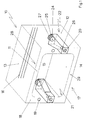
- Figure 1 shows a housing of a television set in perspective.
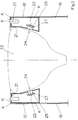
- Figure 2 shows a sectional view through a housing of a television set.
- FIG 1 is a device housing 10 of a television set shown.
- This device housing 10 is formed by the device front surface 11, the two device side surfaces 12, the roof surface 13 and the floor 14 and the rear front 15.
- the rear front 15 is provided with cooling openings 16.
- the cooling openings 16 can also be arranged in the roof surface 13 and in the device side surfaces 12.
- the front face 11 of the device has two openings 19, 20, one above the other, in the two side regions 18 of the front face 11 of the device.
- the openings 19 are provided for receiving mid-range speakers. When using tweeters and mid-range speakers, the openings 19 per side area 18 must be doubled.
- the loudspeaker housings 22 are attached to the rear 21 of the front face 11 of the device in the area of the openings 20, the sides of the loudspeaker housings 22 directly pointing to the front face 11 of the device and the side faces 12 of the device being formed by the front face 11 of the device and the respective side faces 12 of the device.
- the mutually facing surfaces of the two loudspeaker housings 22 run parallel to one another in the front region close to the device front surface 11 and then taper towards one another. This design of the loudspeaker housing 22 was therefore chosen in order to optimally use the space formed for the respective device side surface 12 when the picture tube is inserted, but not shown in this figure.
- any other shape of the loudspeaker housing 22 is also possible, provided that it is ensured that at least one of the housing surfaces of the loudspeaker housing 22 is designed such that it is sufficiently large for the interior of the device indicative outer opening 24 into which the bass speaker can be inserted. 1, these outer openings 24 are arranged on the side of the loudspeaker housing 22 facing the rear front 15 of the device housing 10, in FIG. 2 these outer openings 24 are located on the surface of the loudspeaker housing 22 which lies opposite the picture tube 22.
- the bass reflex tubes 26 are inserted at the openings 20, which - as is particularly emphasized in FIG. 1 - have the same opening cross section as the openings 19 and are guided into the loudspeaker housing 22.
- the bass loudspeakers 25 are inserted into the outer openings 24 of the loudspeaker housing 22, the voice coils 27 lying outside in FIG. 1 and inside the loudspeaker housing 22 in FIG. 2.
- the use of the bass loudspeaker 25 in the outer openings 24 ensures that the sound pressure emitted by the respective bass loudspeaker 25 is partly radiated through the bass reflex tube 26 at the front and partly through the cooling openings 16.
- the loudspeaker housing 22 can be equipped with materials (not shown) for influencing the sound.
- FIG. 2 which shows a section through a device housing 10 of a television set in the area of the loudspeaker housings 22, illustrates that the loudspeaker housings 22 adjacent to the picture tube 23 are partly formed by the front surface 11 and the side surfaces 12 of the device.
- the remaining part of the speaker housing 22 is formed as a molded part and on the edges K with the back 21 of the front face 11 and the Device housing side surfaces 12 glued.
- the molded part can also be fastened to the device front surface 11 and the device side surface 12 in a different manner, for example by screwing or clamping.
- the area of application of the loudspeaker boxes is not limited to the side areas 18 of the front face of the device. Rather, applications are also possible in which the loudspeaker housing 22 is arranged between the roof surface 13 and the picture tube 23 and the floor 14 and the picture tube 23. In the case of mono television sets, the application of the arrangement according to the invention can be restricted to a side area 18 and the head or bottom area 28, 29.
- loudspeaker housings 22 are not at least partially formed by the device housing 10, as shown in the figures, these loudspeaker housings 22 can be inserted and connected very quickly as a compact component in the device housing 10.
- the disadvantage here is the fact that the space between the picture tube 23 and the respective device side surface 12 is reduced by the thickness of the speaker wall pointing towards the device side surface.
Abstract
Description
Die Erfindung befaßt sich mit der Lautsprecheranordnung, insbesondere von Baßlautsprechern in Fernsehgeräten.The invention relates to the loudspeaker arrangement, in particular of bass loudspeakers in television sets.
Herkömmlicherweise sind Lautsprecher in Fernsehgeräten in der Gerätefrontfläche oder in den Geräteseitenflächen integriert. Bei der Integration der Lautsprecher in die Gerätefrontflächen erfordert dies Frontflächenquerschnitte, die im Vergleich zu Fernsehgeräten, deren Lautsprecher in den Geräteseitenflächen eingelassen sind, relativ großdimensioniert sind. Letzteres gilt insbesondere dann, wenn zur verbesserten Klangwiedergabe neben beispielsweise Hoch- und Mitteltonlautsprechern auch Baßlautspecher zur Anwendung kommen sollen. Dies beruht darauf, daß zu einer guten Baßwiedergabe die Baßlautsprecher im Vergleich zu den Hoch- und Mitteltonlautsprechern sowie auch zu Mittelhochtonlautsprechern wesentlich größere Querschnitte erfordern.Speakers are conventionally integrated in television sets in the front of the device or in the side of the device. When integrating the loudspeakers into the front surfaces of the device, this requires front surface cross sections which are relatively large in size in comparison to television sets whose loudspeakers are embedded in the side surfaces of the device. The latter applies in particular if, in addition to, for example, tweeters and midrange speakers, bass speakers are also to be used for improved sound reproduction. This is based on the fact that for a good bass reproduction the bass speakers require much larger cross-sections in comparison to the tweeters and mid-range speakers as well as to the mid-high speakers.
Der Erfindung liegt die Aufgabe zugrunde, eine Baßlautsprecheranordnung für Fernsehgeräte zu schaffen, die bei großdimensionierten Baßlautsprechern und damit dem gewährleisteten guten Klangverhalten keine größeren Öffnungsquerschnitte in der Gerätefrontfläche erfordern, als Hoch- und Mitteltonlautsprecher beziehungsweise Mittelhochtonlautsprecher.The invention has for its object to provide a bass speaker assembly for televisions that do not require larger opening cross-sections in the front face of the device than tweeters and midrange speakers or mid-high speakers in large-dimension bass speakers and thus the guaranteed good sound behavior.
Diese Aufgabe wird dadurch gelöst, daß die Baßlautsprecher in eine zum Geräteinneren hinweisende Außenöffnung des Lautsprechergehäuses eingesetzt sind, so daß ein Teil des vom Baßlautsprecher erzeugten Schalldrucks durch ein Baßreflexrohr frontseitig und der andere Teil des Schalldrucks im Geräteinneren durch die Kühlöffnungen, die in der dem Bildschirm abgewandten Gehäusehälfte angeordnet sind, abgestrahlt wird und zum Diffusschallfeld beiträgt.This object is achieved in that the bass speakers are inserted into an external opening of the speaker housing pointing towards the inside of the device, so that part of the sound pressure generated by the bass speaker through a bass reflex tube on the front and the other part of the sound pressure inside the device through the cooling openings in the screen are arranged facing away from the housing, is emitted and contributes to the diffuse sound field.
Vorteilhafte Aus- und Weiterbildungen der Erfindung sind in den beiden Unteransprüchen ausgeführt.Advantageous further developments of the invention are set out in the two subclaims.
Werden nach Anspruch 2 die Öffungsquerschnitte der Baßreflexrohre kleiner/gleich den Öffnungsquerschnitten für die übrigen Lautsprecher ausgebildet, lassen sich sehr schmale Seitenbereiche bzw. Kopf- oder Bodenbereiche ausbilden, ohne daß deswegen die Klangqualität der Baßwiedergabe gemindert wird. Sind, wie in Anspruch 3 beansprucht, die Außenöffnungen in den Lautsprechergehäusen entweder der Bildröhre oder der Rückwand des Gerätegehäuses zugewandt, zeigen die in diese Außenöffnungen des Lautsprechergehäuses eingesetzten Baßlautsprecher ihr bestes Klangverhalten.If the opening cross sections of the bass reflex tubes are made smaller / equal to the opening cross sections for the other speakers, very narrow side areas or head or bottom areas can be formed without the sound quality of the bass reproduction being reduced as a result. If, as claimed in claim 3, the outer openings in the loudspeaker housings either face the picture tube or the rear wall of the device housing, the bass loudspeakers used in these outer openings of the loudspeaker housing show their best sound behavior.
Wird nach Unteranspruch 4 das jeweilige Lautsprechergehäuse teilweise von der Geräteseitenfläche und der Rückseite der Gerätefrontfläche gebildet, hat dies neben dem Vorteil der Materialersparnis auch den Vorteil, daß nach Wegfall der zur Gehäuseseitenfläche hinweisenden Fläche der Raum zwischen Bildschirm und den Gehäuseseitenflächen besser ausgenutzt wird.If the respective loudspeaker housing is partially formed by the device side surface and the rear of the device front surface according to subclaim 4, this has, in addition to the advantage of material savings, the advantage that the space between the screen and the housing side surfaces is better utilized after the surface facing the housing side surface has been eliminated.
Figur 1 zeigt ein Gehäuse eines Fernsehgeräts in perspektivischer Darstellung.Figure 1 shows a housing of a television set in perspective.
Figur 2 zeigt eine Schnittdarstellung durch ein Gehäuse eines Fernsehgeräts.Figure 2 shows a sectional view through a housing of a television set.
Die Erfindung wird nun anhand der beiden Figuren näher beschrieben. Gleiche Bauteile in den Figuren haben gleiche Bezugszeichen.The invention will now be described with reference to the two figures. The same components in the figures have the same reference numerals.
In Figur 1 ist ein Gerätegehäuse 10 eines Fernsehgerätes dargestellt. Dieses Gerätegehäuse 10 wird von der Gerätefrontfläche 11, den beiden Geräteseitenflächen 12, der Dachfläche 13 und dem Boden 14 sowie der Rückfront 15 gebildet. Die Rückfront 15 ist mit Kühlöffnungen 16 versehen. Es wird darauf hingewiesen, daß in einem anderen, nicht dargestellten Ausführungsbeispiel die Kühlöffnungen 16 auch in der Dachfläche 13 sowie in den Geräteseitenflächen 12 angeordnet sein können. Die Gerätefrontfläche 11 weist neben der Öffnung 17, in die die in dieser Figur nicht dargestellte Bildröhre 23 eingreift, in den beiden Seitenbereichen 18 der Gerätefrontfläche 11 jeweils zwei übereinanderliegende Öffnungen 19, 20 auf. Die Öffnungen 19 sind zur Aufnahme von Mittelhochtonlautsprechern vorgesehen. Bei Einsatz von Hoch- und Mitteltonlautsprechern sind die Öffnungen 19 pro Seitenbereich 18 zu verdoppeln. An der Rückseite 21 der Gerätefrontfläche 11 sind im Bereich der Öffnungen 20 die Lautsprechergehäuse 22 angesetzt, wobei die zur Gehäusefrontfläche 11 und den Geräteseitenflächen 12 unmittelbar hinweisenden Seiten der Lautsprechergehäuse 22 von der Gerätefrontfläche 11 und den jeweiligen Geräteseitenflächen 12 gebildet werden. Die einander zugewandten Flächen der beiden Lautsprechergehäuse 22 verlaufen im vorderen, der Gerätefrontfläche 11 nahen Bereich parallel zueinander und sodann konisch aufeinander zu. Diese Formgebung der Lautsprechergehäuse 22 wurde deshalb gewählt, um den bei eingesetzter - jedoch in dieser Figur nicht dargestellter - Bildröhre den zur jeweiligen Geräteseitenfläche 12 gebildeten Raum optimal zu nutzen. Im übrigen wird darauf hingewiesen, daß auch jede andere Formgebung der Lautsprechergehäuse 22 möglich ist, sofern sichergestellt ist, daß zumindest eine der Gehäuseflächen des Lautsprechergehäuses 22 so beschaffen ist, daß eine ausreichend große, zum Geräteinneren hinweisende Außenöffnung 24 aufnehmen kann, in die der Baßlautsprecher eingesetzt werden kann. Während in Figur 1 diese Außenöffnungen 24 an der der Rückfront 15 des Gerätegehäuses 10 zugewandten Seite des Lautsprechergehäuses 22 angeordnet sind, befinden sich in Figur 2 diese Außenöffnungen 24 an der Fläche des Lautsprechergehäuses 22, die der Bildröhre 22 gegenüberliegt.In Figure 1 is a
Von der Gerätefrontfläche 11 aus sind an den Öffnungen 20, welche - wie Figur 1 besonders hervorhebt - den gleichen Öffnungsquerschnitt wie die Öffnungen 19 aufweisen, die Baßreflexrohre 26 eingesetzt und ins Lautsprechergehäuse 22 geführt. In die Außenöffnungen 24 des Lautsprechergehäuses 22 sind die Baßlautsprecher 25 eingesetzt, wobei in Figur 1 die Schwingspulen 27 außerhalb und in Figur 2 innerhalb des Lautsprechergehäuses 22 liegen. Durch den Einsatz der Baßlautsprecher 25 in den Außenöffnungen 24 wird gewährleistet, daß der vom jeweiligen Baßlautsprecher 25 abgegebene Schalldruck zum Teil durch das Baßreflexrohr 26 frontseitig und zum Teil durch die Kühlöffnungen 16 abgestrahlt wird. Die Lautsprechergehäuse 22 können ebenso wie das Geräteinnere mit nicht dargestellten Materialien zur Klangbeeinflussung ausgestattet sein.From the
Figur 2, welche einen Schnitt durch ein Gerätegehäuse 10 eines Fernsehgeräts im Bereich der Lautsprechergehäuse 22 zeigt, verdeutlicht, daß die der Bildröhre 23 nebengeordneten Lautsprechergehäuse 22 zum Teil von der Gerätefrontfläche 11 und den Geräteseitenflächen 12 gebildet sind. Der übrige Teil der Lautsprechergehäuse 22 ist als Formteil ausgebildet und an den Kanten K mit der Rückseite 21 der Gerätefrontfläche 11 sowie den Gerätegehäuseseitenflächen 12 verklebt. Die Befestigung des Formteils an der Gerätefrontfläche 11 und den Geräteseitenfläche 12 kann auch in anderer Weise realisiert sein, etwa durch Verschrauben oder Verklammern.FIG. 2, which shows a section through a
Letztlich bleibt hervorzuheben, daß der Anwendungsbereich der Lautsprecherboxen nicht nur auf die Seitenbereiche 18 der Gerätefrontfläche beschränkt ist. Vielmehr sind auch Anwendungen möglich, bei denen die Lautsprechergehäuse 22 zwischen der Dachfläche 13 und der Bildröhre 23 sowie dem Boden 14 und der Bildröhre 23 angeordnet sind. Bei Mono-Fernsehgeräten kann die Anwendung der erfindungsgemäßen Anordnung auf einen Seitenbereich 18 sowie den Kopf- oder Bodenbereich 28, 29 beschränkt sein.Ultimately, it should be emphasized that the area of application of the loudspeaker boxes is not limited to the
Werden die Lautsprechergehäuse 22 nicht - wie in den Figuren dargestellt - zumindest teilweise durch das Gerätegehäuse 10 gebildet, lassen sich diese Lautsprechergehäuse 22 sehr schnell als Kompaktbauteil in das Gerätegehäuse 10 einsetzen und verbinden. Nachteilig ist hierbei neben dem höheren Materialaufwand vor allem der Umstand, daß der Zwischenraum zwischen der Bildröhre 23 und der jeweiligen Geräteseitenfläche 12 um die Dicke der zur Geräteseitenfläche hinweisenden Lautsprecherwandung verringert wird.If the
Claims (4)
dadurch gekennzeichnet,
daß die Lautsprechergehäuse (22) eine zum Gerätegehäuseinneren hinweisende Außenöffnung (24) aufweisen, in die der jeweilige Baßlautsprecher (25) eingesetzt ist, so daß ein Teil des vom Baßlautsprecher (25) erzeugten Schalldrucks durch ein Baßreflexrohr (26) frontseitig und der andere Teil des Schalldrucks im Geräteinneren durch die Kühlöffnungen (16) abgestrahlt wird und so zum Diffusschallfeld beiträgt.TV,
characterized by
that the loudspeaker housing (22) has an external opening (24) pointing towards the interior of the device housing have, in which the respective bass speaker (25) is inserted, so that part of the sound pressure generated by the bass speaker (25) through a bass reflex tube (26) on the front and the other part of the sound pressure inside the device through the cooling openings (16) and so on contributes to the diffuse sound field.
dadurch gekennzeichnet,
daß der Öffnungsquerschnitt des Baßreflexrohres (27) in der Gerätefrontfläche (11) </= dem Öffnungsquerschnitt für die Hoch-und Mitteltonlautsprecher bzw. Mittelhochtonlautsprecher ist.Television set according to claim 2,
characterized by
that the opening cross section of the bass reflex tube (27) in the front face of the device (11) is </ = the opening cross section for the high and mid-range loudspeakers or mid-high range loudspeakers.
dadurch gekennzeichnet,
daß die Außenöffnungen (24) in den Lautsprechergehäusen (22) der Bildröhre (23) oder der Rückwand (15) des Gerätegehäuses (10) zugewandt sind.Television set according to one of the preceding claims,
characterized by
that the outer openings (24) in the loudspeaker housings (22) face the picture tube (23) or the rear wall (15) of the device housing (10).
dadurch gekennzeichnet,
daß das jeweilige Lautsprechergehäuse (22) zumindest teilweise vom Gerätegehäuse (10), insbesondere den Geräteseitenflächen (12) und der Rückseite (21) der Gerätefrontfläche (11) gebildet wird.Television set according to one of the preceding claims,
characterized by
that the respective loudspeaker housing (22) is at least partially formed by the device housing (10), in particular the device side surfaces (12) and the rear side (21) of the device front surface (11).
Applications Claiming Priority (2)
| Application Number | Priority Date | Filing Date | Title |
|---|---|---|---|
| DE4022370 | 1990-07-13 | ||
| DE19904022370 DE4022370A1 (en) | 1990-07-13 | 1990-07-13 | INTEGRATED TELEVISION SPEAKER BOX |
Publications (2)
| Publication Number | Publication Date |
|---|---|
| EP0465902A2 true EP0465902A2 (en) | 1992-01-15 |
| EP0465902A3 EP0465902A3 (en) | 1992-04-22 |
Family
ID=6410240
Family Applications (1)
| Application Number | Title | Priority Date | Filing Date |
|---|---|---|---|
| EP19910110339 Withdrawn EP0465902A3 (en) | 1990-07-13 | 1991-06-22 | Integrated television loudspeaker box |
Country Status (2)
| Country | Link |
|---|---|
| EP (1) | EP0465902A3 (en) |
| DE (1) | DE4022370A1 (en) |
Families Citing this family (3)
| Publication number | Priority date | Publication date | Assignee | Title |
|---|---|---|---|---|
| DE9307838U1 (en) * | 1993-05-25 | 1993-07-22 | Nokia (Deutschland) Gmbh, 7530 Pforzheim, De | |
| DE19806509B4 (en) * | 1998-02-17 | 2007-12-13 | Harman Becker Automotive Systems Gmbh | Device for information reproduction |
| CN114390402B (en) * | 2022-01-04 | 2024-04-26 | 杭州老板电器股份有限公司 | Audio injection control method and device for range hood and range hood |
Citations (4)
| Publication number | Priority date | Publication date | Assignee | Title |
|---|---|---|---|---|
| GB624896A (en) * | 1947-02-20 | 1949-06-17 | Henry Ibbotson | Improvements in or relating to television receiving apparatus |
| GB2102243A (en) * | 1981-07-18 | 1983-01-26 | Int Standard Electric Corp | Television receiver for stereophonic sound reproduction |
| EP0117487A1 (en) * | 1983-02-22 | 1984-09-05 | Deutsche Thomson-Brandt GmbH | Television apparatus with an internal bass speaker |
| EP0342117A1 (en) * | 1988-05-06 | 1989-11-15 | Societe Electronique De La Region Pays De Loire | Sound system, in particular a stereophonic one, for television receivers with an integrated large-sized woofer |
Family Cites Families (6)
| Publication number | Priority date | Publication date | Assignee | Title |
|---|---|---|---|---|
| DE7639267U1 (en) * | 1976-12-15 | 1977-05-12 | Graetz Gmbh & Co Ohg, 5990 Altena | TELEVISION RECEIVER HOUSING WITH INTEGRATED SPEAKER BOX |
| DE3405128A1 (en) * | 1984-02-14 | 1985-08-22 | Standard Elektrik Lorenz Ag, 7000 Stuttgart | DEVICE FOR STEREOPHONIC SOUND PLAYBACK IN A TELEVISION RECEIVER |
| DE3819217A1 (en) * | 1988-06-06 | 1989-12-07 | Meggl Friedemann | Loudspeaker system |
| DE3829278A1 (en) * | 1988-08-30 | 1990-03-01 | Telefunken Fernseh & Rundfunk | SPEAKER ARRANGEMENT FOR AN HDTV TELEVISION RECEIVER |
| DE3835539A1 (en) * | 1988-10-19 | 1990-04-26 | Thomson Brandt Gmbh | SPEAKER BOX FOR TELEVISION AND OTHER DEVICES |
| DE3842949A1 (en) * | 1988-12-21 | 1990-06-28 | Grundig Emv | TELEVISION WITH A CASE MADE OF PLASTIC |
-
1990
- 1990-07-13 DE DE19904022370 patent/DE4022370A1/en not_active Withdrawn
-
1991
- 1991-06-22 EP EP19910110339 patent/EP0465902A3/en not_active Withdrawn
Patent Citations (4)
| Publication number | Priority date | Publication date | Assignee | Title |
|---|---|---|---|---|
| GB624896A (en) * | 1947-02-20 | 1949-06-17 | Henry Ibbotson | Improvements in or relating to television receiving apparatus |
| GB2102243A (en) * | 1981-07-18 | 1983-01-26 | Int Standard Electric Corp | Television receiver for stereophonic sound reproduction |
| EP0117487A1 (en) * | 1983-02-22 | 1984-09-05 | Deutsche Thomson-Brandt GmbH | Television apparatus with an internal bass speaker |
| EP0342117A1 (en) * | 1988-05-06 | 1989-11-15 | Societe Electronique De La Region Pays De Loire | Sound system, in particular a stereophonic one, for television receivers with an integrated large-sized woofer |
Also Published As
| Publication number | Publication date |
|---|---|
| EP0465902A3 (en) | 1992-04-22 |
| DE4022370A1 (en) | 1992-01-16 |
Similar Documents
| Publication | Publication Date | Title |
|---|---|---|
| DE4446690B4 (en) | Speaker layout | |
| DE3037496C2 (en) | Loudspeaker system for playback in the mid-range and / or low-frequency range | |
| DE4121408A1 (en) | PLAYBACK FOR MOTOR VEHICLES | |
| DE3317518A1 (en) | SPEAKER BOX WITH INTEGRATED ACOUSTIC BAND PASS FILTER | |
| DE4031742A1 (en) | CALOTH HIGH TONE SPEAKER | |
| DE3933170A1 (en) | METHOD AND DEVICE FOR STEREOPHONE SOUND PLAYBACK | |
| DE19654156A1 (en) | Loudspeaker unit covering wide frequency range | |
| DE3405128A1 (en) | DEVICE FOR STEREOPHONIC SOUND PLAYBACK IN A TELEVISION RECEIVER | |
| DE2839111A1 (en) | SPEAKER SYSTEM | |
| EP2508008A1 (en) | Flat loudspeaker | |
| DE102006059197A1 (en) | earphones | |
| DE2236306A1 (en) | SOUND RADIATION SYSTEM | |
| EP2811756A1 (en) | Loudspeaker | |
| DE3818366A1 (en) | SPEAKER SYSTEM | |
| EP0465902A2 (en) | Integrated television loudspeaker box | |
| DE212013000301U1 (en) | Horn-shaped multipoint excitation loudspeaker box | |
| DE3144545A1 (en) | Loudspeaker system | |
| DE3130234A1 (en) | Loudspeaker enclosure or combination for stereo reproduction | |
| EP0692922B1 (en) | Cabinet for bass-loudspeaker | |
| EP0372186B1 (en) | Loudspeaker boxes for a television set and other apparatuses | |
| EP0575895B1 (en) | Speaker arrangement for television apparatus | |
| DE102015215429A1 (en) | Arrangement for holding a device and device | |
| EP0518041B1 (en) | Ventilated loudspeaker | |
| DE4108409A1 (en) | Acoustic coupler for loudspeaker - uses ring shaped horn structure formed from two circular shells standing back to back | |
| DE10011732B4 (en) | TV cabinet and TV with it |
Legal Events
| Date | Code | Title | Description |
|---|---|---|---|
| PUAI | Public reference made under article 153(3) epc to a published international application that has entered the european phase |
Free format text: ORIGINAL CODE: 0009012 |
|
| AK | Designated contracting states |
Kind code of ref document: A2 Designated state(s): DE ES FR GB IT NL SE |
|
| PUAL | Search report despatched |
Free format text: ORIGINAL CODE: 0009013 |
|
| RAP1 | Party data changed (applicant data changed or rights of an application transferred) |
Owner name: NOKIA (DEUTSCHLAND) GMBH |
|
| AK | Designated contracting states |
Kind code of ref document: A3 Designated state(s): DE ES FR GB IT NL SE |
|
| 17P | Request for examination filed |
Effective date: 19920612 |
|
| 17Q | First examination report despatched |
Effective date: 19940317 |
|
| STAA | Information on the status of an ep patent application or granted ep patent |
Free format text: STATUS: THE APPLICATION IS DEEMED TO BE WITHDRAWN |
|
| 18D | Application deemed to be withdrawn |
Effective date: 19950607 |