EP0518041B1 - Ventilated loudspeaker - Google Patents
Ventilated loudspeaker Download PDFInfo
- Publication number
- EP0518041B1 EP0518041B1 EP92107233A EP92107233A EP0518041B1 EP 0518041 B1 EP0518041 B1 EP 0518041B1 EP 92107233 A EP92107233 A EP 92107233A EP 92107233 A EP92107233 A EP 92107233A EP 0518041 B1 EP0518041 B1 EP 0518041B1
- Authority
- EP
- European Patent Office
- Prior art keywords
- loudspeaker
- flow channels
- mid
- frame
- range
- Prior art date
- Legal status (The legal status is an assumption and is not a legal conclusion. Google has not performed a legal analysis and makes no representation as to the accuracy of the status listed.)
- Expired - Lifetime
Links
- 239000012528 membrane Substances 0.000 claims description 10
- 239000011324 bead Substances 0.000 claims description 2
- 238000009434 installation Methods 0.000 claims description 2
- 239000011810 insulating material Substances 0.000 claims 1
- 238000013016 damping Methods 0.000 description 9
- 239000000463 material Substances 0.000 description 3
- 230000002093 peripheral effect Effects 0.000 description 2
- 230000015572 biosynthetic process Effects 0.000 description 1
- 238000010276 construction Methods 0.000 description 1
- 230000008878 coupling Effects 0.000 description 1
- 238000010168 coupling process Methods 0.000 description 1
- 238000005859 coupling reaction Methods 0.000 description 1
- 238000009826 distribution Methods 0.000 description 1
- 238000009828 non-uniform distribution Methods 0.000 description 1
- 238000009827 uniform distribution Methods 0.000 description 1
Images


Classifications
-
- H—ELECTRICITY
- H04—ELECTRIC COMMUNICATION TECHNIQUE
- H04R—LOUDSPEAKERS, MICROPHONES, GRAMOPHONE PICK-UPS OR LIKE ACOUSTIC ELECTROMECHANICAL TRANSDUCERS; DEAF-AID SETS; PUBLIC ADDRESS SYSTEMS
- H04R1/00—Details of transducers, loudspeakers or microphones
- H04R1/02—Casings; Cabinets ; Supports therefor; Mountings therein
- H04R1/025—Arrangements for fixing loudspeaker transducers, e.g. in a box, furniture
-
- H—ELECTRICITY
- H04—ELECTRIC COMMUNICATION TECHNIQUE
- H04R—LOUDSPEAKERS, MICROPHONES, GRAMOPHONE PICK-UPS OR LIKE ACOUSTIC ELECTROMECHANICAL TRANSDUCERS; DEAF-AID SETS; PUBLIC ADDRESS SYSTEMS
- H04R1/00—Details of transducers, loudspeakers or microphones
- H04R1/20—Arrangements for obtaining desired frequency or directional characteristics
- H04R1/22—Arrangements for obtaining desired frequency or directional characteristics for obtaining desired frequency characteristic only
- H04R1/28—Transducer mountings or enclosures modified by provision of mechanical or acoustic impedances, e.g. resonator, damping means
- H04R1/2869—Reduction of undesired resonances, i.e. standing waves within enclosure, or of undesired vibrations, i.e. of the enclosure itself
- H04R1/2892—Mountings or supports for transducers
- H04R1/2896—Mountings or supports for transducers for loudspeaker transducers
Definitions
- the invention is concerned with the mutual decoupling of several loudspeakers arranged in a housing.
- Loudspeakers of the type specified above have long been known in the prior art. Representative of the training and functioning of loudspeakers, reference is made to the essay in Funkschau 1983, issue 7, page 99 ff.
- a mid-range speaker and a bass speaker are to be used in a speaker cabinet, it is customary to provide the mid-range speaker with a separate volume that is completely decoupled from the woofer volume. This is achieved in that the mid-range speaker is provided with a completely closed housing towards the bass volume.
- This measure must be taken is that without the additional housing realized decoupling of the low-frequency volume from the mid-range volume, the pressure waves of the low-frequency loudspeaker cause deflections of the mid-range loudspeaker. Such deflections lead to distortions in the mid-range. Damage to the mid-range loudspeaker cannot be ruled out due to the deflection of the mid-range loudspeaker due to pressure waves.
- the openings in the loudspeaker basket are filled with a damping means, for example gauze, for damping the low-frequency waves acting on the mid-range loudspeaker. This reduces the influence on the mid-range loudspeaker by the woofer, but not - as with a completely closed housing - not entirely excluded.
- a damping means for example gauze
- mid-range loudspeaker basket of the mid-range loudspeaker design the loudspeaker basket of the mid-range loudspeaker to be completely closed and thus to use the space between the membrane and the loudspeaker basket as "mid-range volume".
- Such mid-range loudspeakers which also form the starting point for the present invention, have a high natural resonance component and are difficult to dampen.
- the invention is therefore based on the object of specifying a mid-range loudspeaker which manages without a separate mid-range volume formed by housing walls, but which has a significantly reduced inherent resonance component.
- the peripheral edge of the loudspeaker basket, with which the loudspeaker is fastened in the opening of the installation wall, is provided with flow channels which connect the space existing between the loudspeaker basket and the membrane to the space in which into which the sound pressure of the speaker is to be emitted.
- a meandering flow channel can have an area B which is provided with damping material.
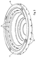
- FIG. 1 shows a mid-high-range loudspeaker 10 which is inserted into the opening 11 of a mounting wall 12 of a box housing.
- the mid-high speaker 10 is essentially conventional.
- the magnet system 13 is firmly attached to one end of the speaker basket 14.
- the membrane 15 is arranged inside the loudspeaker basket 14.
- the upper edge of the diaphragm 15 is connected by means of a bead 16 to the other end of the loudspeaker basket 14 which has a peripheral edge 17.
- the other end of the membrane 15 protrudes with the voice coil 19 arranged on the voice coil support 18 into the air gap 20 of the magnet system 13.
- the centering of the voice coil bobbin 18 in the air gap 20 is performed by a centering membrane 21 in the form of an accordion taken over, which extends between the voice coil bobbin 18 and the inner wall of the speaker basket 14.
- FIGS. 2 and 3 which clearly illustrate this.
- the closedness caused by the closed construction of the loudspeaker basket 14 means that sound waves, which predominate in the space 23 into which the magnet system 13 projects, are unable to influence the diaphragm 15.
- Such sound waves can be sound waves from woofers which are connected to the room 23 and have not been shown in FIG. 1 for reasons of clarity of illustration.
- the loudspeaker 10 In contrast to the conventional design of mid-range loudspeakers 10, the loudspeaker 10 according to the invention has an edge 17 which has flow channels 24 which run inside the edge 17 and the space 25 which extends between the membrane 15, the voice coil former 18 and the loudspeaker basket 14 , connects to the room 26, in which the sound pressure of the speaker 10 is emitted.
- the flow channels 24 are arranged distributed uniformly in the edge 17 of the loudspeaker basket 14. This uniformity of the distribution of the flow channels 24 has the advantage over the non-uniform distribution of the flow channels 24 that the diaphragm 15 cannot tumble during the operation of the loudspeaker 10.
- FIGS. 4a-c show design alternatives for the formation of flow channels 24.
- FIG. 4a shows a very simple embodiment of a flow channel 24. However, it becomes clear in this FIG. 4a that the spaces 25 and 26 are connected to one another via the flow channel 24 and that an unimpeded air exchange between the two spaces 25, 26 is possible.
- Figure 4b shows a flow channel 24 which is meandering. This meandering shape is achieved by a circular ring 27 which has webs 28 of different heights. At the same time, damping is achieved by the meandering design of the flow channel 24.
- damping material 29 is arranged in region B.
- the damping material is a gauze strip.
Description
Die Erfindung befaßt sich mit der gegenseitigen Abkopplung von mehreren in einem Gehäuse angeordneten Lautsprechern.The invention is concerned with the mutual decoupling of several loudspeakers arranged in a housing.
Lautsprecher der oben angegebenen Art sind seit langem im Stand der Technik bekannt. Stellvertretend für die Ausbildung und die Funktionsweise von Lautsprechern sei auf den Aufsatz in der Funkschau 1983, Heft 7, Seite 99 ff, hingewiesen.Loudspeakers of the type specified above have long been known in the prior art. Representative of the training and functioning of loudspeakers, reference is made to the essay in Funkschau 1983, issue 7, page 99 ff.
Sollen beispielsweise ein Mittelton- und ein Basslautsprecher in einem Boxengehäuse eingesetzt werden, so ist es üblich, für den Mitteltonlautsprecher ein eigenes und vom Tieftonlautsprechervolumen völlig abgekoppeltes Volumen vorzusehen. Dies wird dadurch realisiert, daß der Mitteltonlautsprecher zum Bassvolumen hin mit einem völlig geschlossenen Gehäuse versehen ist. Der Grund, warum diese Maßnahme ergriffen werden muß, ist der, daß ohne die durch das zusätzliche Gehäuse realisierte Abkopplung des Tiefton- vom Mitteltonvolumen die Druckwellen des Tieftonlautsprechers Auslenkungen des Mitteltonlautsprechers bewirken. Derartige Auslenkungen führen zu Verzerrungen im Mitteltonbereich. Auch können durch die druckwellenbedingte Auslenkung des Mitteltonlautsprechers Beschädigungen am Mitteltonlautsprecher nicht ausgeschlossen werden.If, for example, a mid-range speaker and a bass speaker are to be used in a speaker cabinet, it is customary to provide the mid-range speaker with a separate volume that is completely decoupled from the woofer volume. This is achieved in that the mid-range speaker is provided with a completely closed housing towards the bass volume. The reason why this measure must be taken is that without the additional housing realized decoupling of the low-frequency volume from the mid-range volume, the pressure waves of the low-frequency loudspeaker cause deflections of the mid-range loudspeaker. Such deflections lead to distortions in the mid-range. Damage to the mid-range loudspeaker cannot be ruled out due to the deflection of the mid-range loudspeaker due to pressure waves.
Hierneben sind Ausbildungen bekannt, die ohne spezielles Mitteltonvolumen auskommen. Gemäß einem dieser Konzepte sind die Öffnungen im Lautsprecherkorb zur Dämpfung der auf den Mitteltonlautsprecher einwirkenden Tieftonwellen mit einem Dämpfungsmittel, beispielsweise Gaze ausgefüllt. Hierdurch wird die Beeinflussung des Mitteltonlautsprechers durch den Tieftonlautsprecher gemindert, jedoch nicht - wie bei einem völlig geschlossenen Gehäuse - gänzlich ausgeschlossen.In addition, training courses are known that do not require a special midtone volume. According to one of these concepts, the openings in the loudspeaker basket are filled with a damping means, for example gauze, for damping the low-frequency waves acting on the mid-range loudspeaker. This reduces the influence on the mid-range loudspeaker by the woofer, but not - as with a completely closed housing - not entirely excluded.
Ein weiteres mitteltonvolumenfreies Konzept besteht darin, den Lautsprecherkorb des Mitteltonlautsprechers vollkommen geschlossen auszubilden und somit den Raum zwischen der Membran und dem Lautsprecherkorb als "Mitteltonvolumen" auszunutzen. Derartige Mitteltonlautsprecher, welche auch gleichzeitig den Ausgangspunkt für die vorliegende Erfindung bilden, haben einen hohen Eigenresonanzanteil und sind schlecht zu bedämpfen.Another concept without mid-range volume is to design the loudspeaker basket of the mid-range loudspeaker to be completely closed and thus to use the space between the membrane and the loudspeaker basket as "mid-range volume". Such mid-range loudspeakers, which also form the starting point for the present invention, have a high natural resonance component and are difficult to dampen.
Daher liegt der Erfindung die Aufgabe zugrunde, einen Mitteltonlautsprecher anzugeben, der ohne separates, durch Gehäusewandungen gebildetes Mitteltonvolumen auskommt, jedoch einen deutlich verminderten Eigenresonanzanteil aufweist.The invention is therefore based on the object of specifying a mid-range loudspeaker which manages without a separate mid-range volume formed by housing walls, but which has a significantly reduced inherent resonance component.
Die Aufgabe wird gemäß Anspruch 1 dadurch gelöst, daß der umlaufende Rand des Lautsprecherkorbes, mit dem der Lautsprecher in der Öffnung der Einbauwand befestigt ist, mit Strömungskanälen versehen ist, die den zwischen dem Lautsprecherkorb und der Membran bestehenden Raum mit dem Raum verbinden, in welchen hinein der Schalldruck des Lautsprechers abgestrahlt werden soll.The object is achieved according to claim 1 in that the peripheral edge of the loudspeaker basket, with which the loudspeaker is fastened in the opening of the installation wall, is provided with flow channels which connect the space existing between the loudspeaker basket and the membrane to the space in which into which the sound pressure of the speaker is to be emitted.
Diese völlige Abkopplung des Mitteltonvolumens vom Tieftonvolumen und die Verkopplung des Raumes zwischen der Membran und dem Lautsprecher mit dem Raum, in welchen hinein der Schalldruch des Mitteltonlautsprechers abgegeben werden soll, bewirkt, daß bei Bewegungen der Membran die Luft durch die Strömungskanäle zwischen den beiden verbundenen Räumen ungehindert hin- und herströmen kann.This complete decoupling of the mid-range volume from the low-frequency volume and the coupling of the space between the diaphragm and the loudspeaker to the space into which the sound pressure of the mid-range loudspeaker is to be emitted, means that when the diaphragm moves, the air flows through the flow channels between the two connected spaces can flow freely back and forth.
Ist gemäß Anspruch 2 die Summe aller Querschnitte der Strömungskanäle der bewegten Luftmenge angepaßt, kann bereits hierdurch eine Bedämpfung erwirkt werden.If, according to claim 2, the sum of all cross-sections of the flow channels is adapted to the amount of air moved, damping can already be achieved in this way.
Weitere Möglichkeiten zur Bedämpfung sind in den Ansprüchen 3 und 4 angegeben. Die dort genannten Maßnahmen können eigenständig oder auch in Kombination mit anderen Maßnahmen ergriffen werden. So kann beispielsweise ein meanderförmig ausgebildeter Strömungskanal einen Bereich B aufweisen, der mit Dämpfungsmaterial versehen ist.Further options for damping are given in claims 3 and 4. The measures mentioned there can be taken independently or in combination with other measures. For example, a meandering flow channel can have an area B which is provided with damping material.
Durch die - in Anspruch 5 angegebene - gleichmäßige Verteilung der Strömungskanäle im Rand des Lautsprechers wird ein Taumeln der Membran während des Betriebs des Lautsprechers weitgehend ausgeschlossen.Due to the uniform distribution of the flow channels in the edge of the loudspeaker, a wobbling of the membrane during the operation of the loudspeaker is largely excluded.
Es zeigen:
- Figur 1
- einen in der Öffnung einer Einbauwand eingesetzten Mitteltonlautsprecher im Schnitt;
- Figur 2
- einen Mitteltonlautsprecher gemäß Figur 1 in Seitenansicht;
- Figur 3
- den in Figur 2 dargestellten Lautsprecherkorb in perspektivischer Ansicht; und
- Figur 4a-c
- drei verschiedene Randausbildungen eines Mittelhochtonlautsprechers.
Wege zum Ausführen der ErfindungShow it:
- Figure 1
- an average mid-range speaker inserted in the opening of a built-in wall;
- Figure 2
- a mid-range speaker according to Figure 1 in side view;
- Figure 3
- the speaker basket shown in Figure 2 in perspective view; and
- Figure 4a-c
- three different edge designs of a mid-high speaker.
Ways of Carrying Out the Invention
Die in Figur 1 gezeigte Anordnung zeigt einen Mittelhochtonlautsprecher 10 der in die Öffnung 11 einer Einbauwand 12 eines Boxengehäuses eingesetzt ist.The arrangement shown in FIG. 1 shows a mid-high-
Der Mittelhochtonlautsprecher 10 ist im wesentlichen herkömmlich ausgebildet. Das Magnetsystem 13 ist an dem einen Ende des Lautsprecherkorbes 14 fest angesetzt. Innerhalb des Lautsprecherkorbes 14 ist die Membran 15 angeordnet. Der obere Rand der Membran 15 ist mittels einer Sicke 16 mit dem anderen, einen umlaufenden Rand 17 aufweisenden Ende des Lautsprecherkorbes 14 verbunden. Das andere Ende der Membran 15 ragt mit der auf dem Schwingspulenträger 18 angeordneten Schwingspule 19 in den Luftspalt 20 des Magnetsystems 13 ein. Die Zentrierung des Schwingspulenträgers 18 im Luftspalt 20 wird von einer ziehharmonikaförmig ausgebildeten Zentriermembran 21 übernommen, die sich zwischen dem Schwingspulenträger 18 und der Innenwand des Lautsprecherkorbes 14 erstreckt.The
Die Mantelfläche 22 des Lautsprecherkorbes 14, welche im vorliegenden Ausführungsbeispiel treppenförmig ausgebildet ist, ist zum Raum 23 völlig durchbruchs- und öffnungsfrei gestaltet. Hierzu sei besonders auf die Figuren 2 und 3 hingewiesen, die dies deutlich veranschaulichen. Die durch die geschlossene Bauweise des Lautsprecherkorbes 14 bewirkte Abgeschlossenheit führt dazu, daß Schallwellen, die in dem Raum 23 vorherrschen, in welchen das Magnetsystem 13 hineinragt, nicht in der Lage sind, auf die Membran 15 Einfluß zu nehmen. Derartige Schallwellen können Schallwellen von Tieftonlautsprechern sein, die mit dem Raum 23 in Verbindung stehen und in Figur 1 aus Gründen der Übersichtlichkeit der Darstellung nicht dargestellt worden sind.The
Abweichend von der herkömmlichen Ausbildung von Mitteltonlautsprechern 10 verfügt der erfindungsgemäße Lautsprecher 10 über einen Rand 17, der über Strömungskanäle 24 verfügt, die innerhalb des Randes 17 verlaufen und den Raum 25, welcher sich zwischen der Membran 15, dem Schwingspulenträger 18 und dem Lautsprecherkorb 14 ausdehnt, mit dem Raum 26 verbindet, in welchem der Schalldruck des Lautsprechers 10 abgestrahlt wird.In contrast to the conventional design of
Obwohl in Figur 1 der Eindruck erweckt wird, daß der zwischen der Membran 15 und dem Lautsprecherkorb 14 liegende Raum 25 durch die Zentriermembran 21 in zwei Kammern unterteilt wird, sei an dieser Stelle ausgeführt, daß die Zentriermembran 21 luftdurchlässig ausgebildet ist und somit beide Kammern als ein Raum 25 angesehen werden können.Although the impression is given in FIG. 1 that the
Anhand der Figuren 2 und 3 läßt sich deutlich entnehmen, daß die Strömungskanäle 24 gleichmäßig im Rand 17 des Lautsprecherkorbes 14 verteilt angeordnet sind. Diese Gleichmäßigkeit der Verteilung der Strömungskanäle 24 hat gegenüber der ungleichmäßigen Verteilung der Strömungskanäle 24 den Vorteil, daß während des Betriebs des Lautsprechers 10 die Membran 15 nicht in Taumelbewegungen geraten kann.It can be clearly seen from FIGS. 2 and 3 that the
In den Figuren 4a-c sind Gestaltungsalternativen für die Ausbildung von Strömungskanälen 24 dargestellt. Figur 4a zeigt ein sehr einfaches Ausführungsbeispiel für ein Strömungskanal 24. Deutlich wird jedoch in dieser Figur 4a, daß die Räume 25 und 26 über den Strömungskanal 24 miteinander in Verbindung stehen und ein ungehinderter Luftaustausch zwischen den beiden Räumen 25, 26 möglich ist.FIGS. 4a-c show design alternatives for the formation of
Figur 4b zeigt einen Strömungskanal 24, der meanderförmig ausgestaltet ist. Diese meanderförmige Gestalt wird durch einen Kreisring 27 erreicht, der unterschiedlich hohe Stege 28 aufweist. Durch die meanderförmige Ausgestaltung des Strömungskanals 24 wird gleichzeitig eine Dämpfung erreicht.Figure 4b shows a
Diese Dämpfung wird bei dem in Figur 4c dargestellten Ausführungsbeispiel dadurch erreicht, daß im Bereich B Dämpfungsmaterial 29 angeordnet ist. Im vorliegenden Ausführungsbeispiel handelt es sich bei dem Dämpfungsmaterial um einen Gazestreifen.In the exemplary embodiment shown in FIG. 4c, this damping is achieved in that damping
Claims (5)
- Loudspeaker, in particular middle-range loudspeaker (10),- having a magnet system (13),- having an approximately conically shaped loudspeaker frame (14), one end of which is joined to the magnet system (13) and the other end of which has a circumferential rim (17), which loudspeaker frame serves to mount the loudspeaker in the opening (11) of the installation wall (12), its circumferential surface (22) being free of perforations and openings, and- having a diaphragm (15) which is inserted into the loudspeaker frame (14), one end of the diaphragm (15) being joined to the rim (17) of the loudspeaker frame (14) by means of a bead (16) and the other end of the membrane (15) entering, along with the moving coil (19) disposed at that point, the air gap (20),characterized in that
the circumferential rim (17) has flow channels (24) which connect the space (25) existing between the loudspeaker frame (14) and the diaphragm (15) to the space (26) into which the acoustic pressure of the loudspeaker (10) is to be radiated. - Loudspeaker according to Claim 1, characterized in that the sum of the cross-sections of all the flow channels (24) is matched in the air volume they have to move.
- Loudspeaker according to Claim 1 or Claim 2, characterized in that the flow channels (24) are of approximately meander-like shape.
- Loudspeaker according to one of Claims 1 to 3, characterized in that each flow channel (24) has a region B which is provided with acoustic insulating material (27).
- Loudspeaker according to one of Claims 1 to 4, characterized in that the flow channels (24) are uniformly distributed in the rim (17) of the loudspeaker frame (14).
Applications Claiming Priority (2)
| Application Number | Priority Date | Filing Date | Title |
|---|---|---|---|
| DE4116342A DE4116342A1 (en) | 1991-05-18 | 1991-05-18 | VENTILATED SPEAKER |
| DE4116342 | 1991-05-18 |
Publications (2)
| Publication Number | Publication Date |
|---|---|
| EP0518041A1 EP0518041A1 (en) | 1992-12-16 |
| EP0518041B1 true EP0518041B1 (en) | 1994-07-27 |
Family
ID=6431969
Family Applications (1)
| Application Number | Title | Priority Date | Filing Date |
|---|---|---|---|
| EP92107233A Expired - Lifetime EP0518041B1 (en) | 1991-05-18 | 1992-04-28 | Ventilated loudspeaker |
Country Status (5)
| Country | Link |
|---|---|
| EP (1) | EP0518041B1 (en) |
| CZ (1) | CZ280864B6 (en) |
| DE (2) | DE4116342A1 (en) |
| HU (1) | HU213437B (en) |
| PL (1) | PL167900B1 (en) |
Family Cites Families (5)
| Publication number | Priority date | Publication date | Assignee | Title |
|---|---|---|---|---|
| DE830354C (en) * | 1948-11-19 | 1952-02-04 | Alexander Schaaf | Loudspeaker for the reproduction of high frequencies with a pressure-relieved membrane |
| DK147490C (en) * | 1981-02-03 | 1985-05-28 | Jamo Hi Fi As | Bass-reflex speaker system |
| WO1984003600A1 (en) * | 1983-03-02 | 1984-09-13 | Brian Douglas Ward | Constant pressure device |
| DE8314251U1 (en) * | 1983-05-13 | 1985-05-09 | Standard Elektrik Lorenz Ag, 7000 Stuttgart | Loudspeaker box with integrated acoustic bandpass filter |
| JP2505047B2 (en) * | 1989-06-20 | 1996-06-05 | パイオニア株式会社 | Speaker system |
-
1991
- 1991-05-18 DE DE4116342A patent/DE4116342A1/en not_active Withdrawn
-
1992
- 1992-04-28 EP EP92107233A patent/EP0518041B1/en not_active Expired - Lifetime
- 1992-04-28 DE DE59200316T patent/DE59200316D1/en not_active Expired - Fee Related
- 1992-05-08 PL PL92294475A patent/PL167900B1/en unknown
- 1992-05-15 HU HU9201605A patent/HU213437B/en not_active IP Right Cessation
- 1992-05-15 CZ CS921482A patent/CZ280864B6/en unknown
Also Published As
| Publication number | Publication date |
|---|---|
| EP0518041A1 (en) | 1992-12-16 |
| HUT63532A (en) | 1993-08-30 |
| DE4116342A1 (en) | 1992-11-19 |
| DE59200316D1 (en) | 1994-09-01 |
| PL294475A1 (en) | 1993-02-22 |
| PL167900B1 (en) | 1995-12-30 |
| HU213437B (en) | 1997-06-30 |
| HU9201605D0 (en) | 1992-08-28 |
| CZ280864B6 (en) | 1996-04-17 |
| CS148292A3 (en) | 1992-12-16 |
Similar Documents
| Publication | Publication Date | Title |
|---|---|---|
| DE3023291C2 (en) | ||
| DE2540680C3 (en) | headphones | |
| DE2755718C2 (en) | Sealed headphones | |
| DE19654156C2 (en) | Speaker unit and speaker system using the speaker unit | |
| DE2536439A1 (en) | SPEAKER SYSTEM | |
| DE2815051A1 (en) | CLOSED HEADPHONES | |
| DE3317518A1 (en) | SPEAKER BOX WITH INTEGRATED ACOUSTIC BAND PASS FILTER | |
| DE69912416T2 (en) | DEVICE WITH A HOUSING THAT CONTAINS A TON CONVERTER AND WITH A CARRIER | |
| DE69736941T2 (en) | Speaker device | |
| DE2461322C3 (en) | Loudspeaker arrangement | |
| EP0518041B1 (en) | Ventilated loudspeaker | |
| DE69908930T2 (en) | TELEPHONE WITH LOW-FREQUENCY ENHANCEMENT MEANS | |
| DE212013000301U1 (en) | Horn-shaped multipoint excitation loudspeaker box | |
| DE3144545A1 (en) | Loudspeaker system | |
| DE69938142T2 (en) | METHOD FOR PLAYBACK AND COLUMN SPEAKER | |
| DE2809052C2 (en) | ||
| DE2739523C2 (en) | ||
| EP0692922B1 (en) | Cabinet for bass-loudspeaker | |
| DE3024777A1 (en) | SPEAKER SYSTEM WITH PLANAR MEMBRANE | |
| DE1762237C3 (en) | Public address system, in particular for low-frequency sound reproduction | |
| DE3447745C2 (en) | ||
| EP1600034B1 (en) | Loudspeaker box | |
| DE2457480C3 (en) | Speaker combination | |
| DE3918654C2 (en) | ||
| DE2703979C3 (en) | Loudspeaker arrangement |
Legal Events
| Date | Code | Title | Description |
|---|---|---|---|
| PUAI | Public reference made under article 153(3) epc to a published international application that has entered the european phase |
Free format text: ORIGINAL CODE: 0009012 |
|
| AK | Designated contracting states |
Kind code of ref document: A1 Designated state(s): BE DE FR GB IT SE |
|
| 17P | Request for examination filed |
Effective date: 19921110 |
|
| 17Q | First examination report despatched |
Effective date: 19931217 |
|
| GRAA | (expected) grant |
Free format text: ORIGINAL CODE: 0009210 |
|
| AK | Designated contracting states |
Kind code of ref document: B1 Designated state(s): BE DE FR GB IT SE |
|
| ITF | It: translation for a ep patent filed |
Owner name: JACOBACCI CASETTA & PERANI S.P.A. |
|
| GBT | Gb: translation of ep patent filed (gb section 77(6)(a)/1977) |
Effective date: 19940728 |
|
| REF | Corresponds to: |
Ref document number: 59200316 Country of ref document: DE Date of ref document: 19940901 |
|
| ET | Fr: translation filed | ||
| EAL | Se: european patent in force in sweden |
Ref document number: 92107233.6 |
|
| PLBE | No opposition filed within time limit |
Free format text: ORIGINAL CODE: 0009261 |
|
| STAA | Information on the status of an ep patent application or granted ep patent |
Free format text: STATUS: NO OPPOSITION FILED WITHIN TIME LIMIT |
|
| 26N | No opposition filed | ||
| PGFP | Annual fee paid to national office [announced via postgrant information from national office to epo] |
Ref country code: FR Payment date: 19970409 Year of fee payment: 6 |
|
| PGFP | Annual fee paid to national office [announced via postgrant information from national office to epo] |
Ref country code: SE Payment date: 19970418 Year of fee payment: 6 |
|
| PGFP | Annual fee paid to national office [announced via postgrant information from national office to epo] |
Ref country code: GB Payment date: 19970421 Year of fee payment: 6 |
|
| PGFP | Annual fee paid to national office [announced via postgrant information from national office to epo] |
Ref country code: BE Payment date: 19970612 Year of fee payment: 6 |
|
| PG25 | Lapsed in a contracting state [announced via postgrant information from national office to epo] |
Ref country code: GB Free format text: LAPSE BECAUSE OF NON-PAYMENT OF DUE FEES Effective date: 19980428 |
|
| PG25 | Lapsed in a contracting state [announced via postgrant information from national office to epo] |
Ref country code: SE Free format text: LAPSE BECAUSE OF NON-PAYMENT OF DUE FEES Effective date: 19980429 |
|
| PG25 | Lapsed in a contracting state [announced via postgrant information from national office to epo] |
Ref country code: FR Free format text: THE PATENT HAS BEEN ANNULLED BY A DECISION OF A NATIONAL AUTHORITY Effective date: 19980430 Ref country code: BE Free format text: LAPSE BECAUSE OF NON-PAYMENT OF DUE FEES Effective date: 19980430 |
|
| PGFP | Annual fee paid to national office [announced via postgrant information from national office to epo] |
Ref country code: DE Payment date: 19980612 Year of fee payment: 7 |
|
| BERE | Be: lapsed |
Owner name: NOKIA (DEUTSCHLAND) G.M.B.H. Effective date: 19980430 |
|
| GBPC | Gb: european patent ceased through non-payment of renewal fee |
Effective date: 19980428 |
|
| EUG | Se: european patent has lapsed |
Ref document number: 92107233.6 |
|
| REG | Reference to a national code |
Ref country code: FR Ref legal event code: ST |
|
| PG25 | Lapsed in a contracting state [announced via postgrant information from national office to epo] |
Ref country code: DE Free format text: LAPSE BECAUSE OF NON-PAYMENT OF DUE FEES Effective date: 20000201 |
|
| PG25 | Lapsed in a contracting state [announced via postgrant information from national office to epo] |
Ref country code: IT Free format text: LAPSE BECAUSE OF NON-PAYMENT OF DUE FEES;WARNING: LAPSES OF ITALIAN PATENTS WITH EFFECTIVE DATE BEFORE 2007 MAY HAVE OCCURRED AT ANY TIME BEFORE 2007. THE CORRECT EFFECTIVE DATE MAY BE DIFFERENT FROM THE ONE RECORDED. Effective date: 20050428 |