EP0464449B1 - Montageverfahren einer Radscheibe an eine Felge und ein so erhaltenes Fahrzeugrad - Google Patents
Montageverfahren einer Radscheibe an eine Felge und ein so erhaltenes Fahrzeugrad Download PDFInfo
- Publication number
- EP0464449B1 EP0464449B1 EP91109929A EP91109929A EP0464449B1 EP 0464449 B1 EP0464449 B1 EP 0464449B1 EP 91109929 A EP91109929 A EP 91109929A EP 91109929 A EP91109929 A EP 91109929A EP 0464449 B1 EP0464449 B1 EP 0464449B1
- Authority
- EP
- European Patent Office
- Prior art keywords
- rim
- disc
- wheel
- weld bead
- axially outer
- Prior art date
- Legal status (The legal status is an assumption and is not a legal conclusion. Google has not performed a legal analysis and makes no representation as to the accuracy of the status listed.)
- Expired - Lifetime
Links
Images


Classifications
-
- B—PERFORMING OPERATIONS; TRANSPORTING
- B60—VEHICLES IN GENERAL
- B60B—VEHICLE WHEELS; CASTORS; AXLES FOR WHEELS OR CASTORS; INCREASING WHEEL ADHESION
- B60B3/00—Disc wheels, i.e. wheels with load-supporting disc body
- B60B3/04—Disc wheels, i.e. wheels with load-supporting disc body with a single disc body not integral with rim, i.e. disc body and rim being manufactured independently and then permanently attached to each other in a second step, e.g. by welding
- B60B3/041—Disc wheels, i.e. wheels with load-supporting disc body with a single disc body not integral with rim, i.e. disc body and rim being manufactured independently and then permanently attached to each other in a second step, e.g. by welding characterised by the attachment of rim to wheel disc
- B60B3/044—Disc wheels, i.e. wheels with load-supporting disc body with a single disc body not integral with rim, i.e. disc body and rim being manufactured independently and then permanently attached to each other in a second step, e.g. by welding characterised by the attachment of rim to wheel disc characterised by cross-sectional details of the attachment, e.g. the profile
-
- B—PERFORMING OPERATIONS; TRANSPORTING
- B21—MECHANICAL METAL-WORKING WITHOUT ESSENTIALLY REMOVING MATERIAL; PUNCHING METAL
- B21D—WORKING OR PROCESSING OF SHEET METAL OR METAL TUBES, RODS OR PROFILES WITHOUT ESSENTIALLY REMOVING MATERIAL; PUNCHING METAL
- B21D53/00—Making other particular articles
- B21D53/26—Making other particular articles wheels or the like
Definitions
- Molded light alloy wheels are enjoying increasing success for passenger vehicles, mainly for aesthetic reasons, and not technical reasons because they are often of comparable weight to sheet metal wheels. The latter retain an important advantage over light alloy wheels in terms of cost price. Despite constant efforts to improve their appearance, they most often add a large-diameter hubcap to cover them entirely or almost entirely, in particular because the connection area between the disc and the rim is unsightly.
- the objective of the present invention is to reconcile the advantages of each of the two categories of wheels indicated.
- the objective of the present invention is therefore to modify the connection of the disc and the rim to improve its appearance.
- the invention provides a method of assembling a disc to a rim in a single piece to form a wheel, consisting in positioning the disc under the axially outer rim seat, in producing a continuous weld bead between the disc and the disc side rim visible after mounting on a hub, characterized in that a finishing operation is carried out by removing material from the weld bead, to ensure visual continuity between the rim and the disc thus assembled, said weld bead being executed so to provide sufficient material.
- a sheet metal wheel obtained by the method according to the invention consisting of a disc and a rim in one piece, the rim having a central mounting groove, and two seats arranged on either side of the groove, each seat being extended at its lateral edge by a rim extending radially outwards, is characterized in that the disc is shaped to come to adapt to the rim at a seat thereof, and in that the axially outer face of the disc, at the peripheral wheel is disposed substantially in the extension of the axially outer face of the rim flange and in that the connection of the disc to the rim is constituted by a continuous weld bead disposed between the disc and the rim on the side of the disc axially outside, and in that the weld bead has undergone a finishing operation by removal of material so that the surface state of the weld bead ensures continuity of for visual me between the disc and the rim.
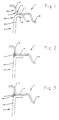
- Figures 1, 2 and 3 show three successive stages and the manufacture of a wheel according to the invention.
- Figures 4, 5 and 6 show three successive stages in the manufacture of another wheel according to the invention.
- Figures 7, 8 and 9 show three successive stages in the manufacture of a third example wheel according to the invention.
- This rim 1 is said to be “in one piece” and therefore comprises a central groove 10 shown partially, for engaging the bead of a tire during mounting, and, on each side, a seat 11 (of which only one is shown) for receiving the bead of said tire when it is mounted on the rim 1.
- the example described relates to wheels for a passenger vehicle: according to the standards in force, the seat 11 is slightly inclined towards inside the rim 1, at an angle of about 5 °.
- the seat 11 is extended, at its lateral edge, by a flange 12, which extends radially outwards.
- This flange 12 is, in the example considered, oriented substantially in a plane perpendicular to the axis of the wheel (axis of rotation not visible in the figures). Between seat 11 and flange 12, there is a connection leave. In other cases, this flange 12 could be inclined, in whole or in part, relative to the axis of the wheel.
- Such a rim 1 is produced by progressive deformation of the sheet. Its radially outer surface, on which the tire is mounted, and its radially inner surface, on which the disc 2 is positioned and fixed, therefore have approximately the same profile, seen in meridian section as in the figures. In particular, we see a boss 14 on the side of the rim that remains visible after mounting the tire. This boss 14 corresponds to the leave 13 for connection between seat 11 and flange 12.
- the disc 2 made of stamped sheet metal, has a central part (not shown) for mounting on a hub, and a peripheral zone 20 extended by a zone which will be called here nesting zone 21 with the rim.
- this connection zone is cylindrical and disposed under the mounting groove 10.
- the mechanical connection between disk 2 and rim 1 is produced by the rivets, by spot welding, or by a weld bead produced at the end of the connection zone, that is to say on the side not visible after mounting on the vehicle, corresponding to the right side on the figures, or by any other equivalent provision.
- the disc 2 is shaped and then positioned with respect to the rim 1 so as to adapt to the rim at a seat of the latter, so that the axially outer face 20A of the disc, at the peripheral zone 20, is disposed substantially in the extension of the axially outer face 12A of the rim 12 of the rim 1.
- these faces 12A and 20A are oriented substantially in a plane perpendicular to the axis of the wheel.
- Figures 3, 6 and 9 show the result of this operation.
- the cord is machined to flatten it, in order to obtain a flat and continuous surface 30 as in FIG. 3. It is also possible to make a groove 31 or a small decorative molding 32, as shown in Figures 6 and 9 respectively.
- the invention makes it possible to compete with the molded wheels from an aesthetic point of view, at an additional manufacturing cost which is very low compared to the difference in cost price between the molded wheels and the sheet metal wheels.
Landscapes
- Engineering & Computer Science (AREA)
- Mechanical Engineering (AREA)
- Butt Welding And Welding Of Specific Article (AREA)
- Automobile Manufacture Line, Endless Track Vehicle, Trailer (AREA)
- Laser Beam Processing (AREA)
- Tyre Moulding (AREA)
Claims (2)
- Verfahren zur Montage einer Scheibe (2) an einer einstückigen Felge (1), um ein Rad zu bilden, welches Verfahren darin besteht, die Scheibe (2) bezüglich der Felge (1) unter dem axial äußeren Sitz (11) der Felge (1) zu positionieren, eine kontinuierliche Schweißnaht (3) zwischen der Scheibe (2) und der Felge (1) auf der nach Montage an einer Nabe sichtbaren Seite der Scheibe herzustellen,
gekennzeichnet durch
eine Endbearbeitung durch Entfernen von Material an der Schweißnaht (3), um eine visuelle Formkontinuität zwischen so zusammengesetzter Felge (1) und Scheibe (2) herzustellen, wobei die Schweißnaht (3) mit ausreichendem Materialauftrag durchgeführt wird. - Blechrad, bestehend aus einer Scheibe (2) und einer einstückigen Felge (1), wobei die Felge (1) eine zentrale Montagenut (10) und zwei auf beiden Seiten der Nut (10) angeordnete Sitze (11) hat, wobei jeder Sitz (11) an seinem seitlichen Rand durch eine Krempe (12) verlängert ist, die sich radial nach außen erstreckt,
dadurch gekennzeichnet,
daß die axial äußere Seite (2A) der Scheibe (2) in Höhe des Randabschnitts (20) im wesentlichen in Verlängerung der axial äußeren Seite (12A) der Krempe der Felge (1) angeordnet ist, und die Verbindung der Scheibe (2) mit der Felge (1) durch eine kontinuierliche Schweißnaht (3) gebildet ist, die zwischen der Scheibe (2) und der Felge (1) auf der axial äußeren Seite der Scheibe (2) gebildet ist, und daß die Schweißnaht (3) eine Endbearbeitung durch Materialabtrag durchlaufen hat, so daß der Zustand der Oberfläche der Schweißnaht (3) die visuelle Formkontinuität zwischen der Scheibe (2) und der Felge (1) sicherstellt.
Applications Claiming Priority (2)
| Application Number | Priority Date | Filing Date | Title |
|---|---|---|---|
| FR9008666A FR2664206A1 (fr) | 1990-07-05 | 1990-07-05 | Procede d'assemblage d'un disque de roue a une jante et roue ainsi obtenue. |
| FR9008666 | 1990-07-05 |
Publications (2)
| Publication Number | Publication Date |
|---|---|
| EP0464449A1 EP0464449A1 (de) | 1992-01-08 |
| EP0464449B1 true EP0464449B1 (de) | 1994-08-31 |
Family
ID=9398489
Family Applications (1)
| Application Number | Title | Priority Date | Filing Date |
|---|---|---|---|
| EP91109929A Expired - Lifetime EP0464449B1 (de) | 1990-07-05 | 1991-06-18 | Montageverfahren einer Radscheibe an eine Felge und ein so erhaltenes Fahrzeugrad |
Country Status (5)
| Country | Link |
|---|---|
| EP (1) | EP0464449B1 (de) |
| AT (1) | ATE110645T1 (de) |
| DE (1) | DE69103695T2 (de) |
| ES (1) | ES2060251T3 (de) |
| FR (1) | FR2664206A1 (de) |
Families Citing this family (5)
| Publication number | Priority date | Publication date | Assignee | Title |
|---|---|---|---|---|
| DE9400171U1 (de) * | 1994-01-07 | 1994-03-03 | Vaw Ver Aluminium Werke Ag | Blechrad |
| DE19542280C2 (de) * | 1995-11-01 | 1997-10-23 | Mannesmann Ag | Zweiteiliges geschweißtes Fahrzeugrad |
| MXPA02012757A (es) * | 2000-06-29 | 2003-05-14 | Michelin Rech Tech | Rueda para vehiculo con montaje bajo asiento.. |
| FR3004145B1 (fr) * | 2013-04-03 | 2016-02-26 | Peugeot Citroen Automobiles Sa | Roue de vehicule, en particulier de vehicule automobile |
| FR3022186B1 (fr) * | 2014-06-16 | 2016-10-14 | Peugeot Citroen Automobiles Sa | Procede de soudage d'une piece en acier sur une piece en aluminium, par descente gravitationnelle d'un bain de soudure |
Family Cites Families (4)
| Publication number | Priority date | Publication date | Assignee | Title |
|---|---|---|---|---|
| GB371220A (en) * | 1930-08-21 | 1932-04-21 | Goodyear Tire & Rubber | Improvements in or relating to vehicle wheels with tyre supporting rims |
| US2083326A (en) * | 1934-10-08 | 1937-06-08 | Budd Wheel Co | Vehicle wheel |
| DE3345638A1 (de) * | 1983-12-16 | 1985-06-20 | Späth GmbH & Co KG, 7760 Radolfzell | Felge fuer kraftfahrzeuge und dergleichen |
| YU44944B (en) * | 1987-04-01 | 1991-04-30 | Markelj Zlatko | Improved process of car wheel repairing |
-
1990
- 1990-07-05 FR FR9008666A patent/FR2664206A1/fr active Pending
-
1991
- 1991-06-18 DE DE69103695T patent/DE69103695T2/de not_active Expired - Fee Related
- 1991-06-18 EP EP91109929A patent/EP0464449B1/de not_active Expired - Lifetime
- 1991-06-18 ES ES91109929T patent/ES2060251T3/es not_active Expired - Lifetime
- 1991-06-18 AT AT91109929T patent/ATE110645T1/de not_active IP Right Cessation
Also Published As
| Publication number | Publication date |
|---|---|
| ES2060251T3 (es) | 1994-11-16 |
| DE69103695T2 (de) | 1995-03-16 |
| DE69103695D1 (de) | 1994-10-06 |
| EP0464449A1 (de) | 1992-01-08 |
| ATE110645T1 (de) | 1994-09-15 |
| FR2664206A1 (fr) | 1992-01-10 |
Similar Documents
| Publication | Publication Date | Title |
|---|---|---|
| EP0579525B1 (de) | Verfahren zur Herstellung einer Fahrradfelge und nach diesem Verfahren hergestellte Felge | |
| EP1904362B1 (de) | Verfahren zur montage einer kraftfahrzeugachse mit aufhängungsarmen und montiertem querträger zwischen den armen und entsprechende achse | |
| EP1451023B1 (de) | Kraftfahrzeugradteller, insbesondere für personenkraftwagen | |
| FR2465601A1 (fr) | Roue de vehicule automobile en deux parties assemblees | |
| EP1453687B1 (de) | Scheibe eines kraftfahrzeugrades, insbesondere für einen personenkraftwagen | |
| EP0464449B1 (de) | Montageverfahren einer Radscheibe an eine Felge und ein so erhaltenes Fahrzeugrad | |
| EP1671811B1 (de) | Leichtrad insbesondere für landwirtschaftliche Maschinen | |
| FR2620389A1 (fr) | Stabilisateur pour vehicules automobiles | |
| EP0799721B1 (de) | Rad für Fahrzeuge | |
| FR2463708A1 (fr) | Boitier d'absorption d'energie, en cas de choc, s'intercalant entre le tube de direction et le volant de vehicules automobiles | |
| EP1341678B1 (de) | Radfelge mit nach aussen geneigten schultern und mit strangpressverfahren hergestellt | |
| EP3720645B1 (de) | Verfahren zum befestigen eines metallbauteils an einem durch biegen und schweissen von blech erhaltenen metallrohr sowie entsprechender achskopf | |
| FR2800697A1 (fr) | Poutre de vehicule automobile integrant un montant de baie et un brancard de pavillon | |
| EP1232880A1 (de) | Gestanzte Radscheibe mit Speichen | |
| WO2004103730A2 (fr) | Nouvelle roue notamment en alliage leger pour vehicule automobile, et procede de fabrication d’une telle roue | |
| FR2851801A1 (fr) | Dispositif de montage d'une structure rotative sur un axe | |
| FR3102971A1 (fr) | Roue de véhicule fabriquée par soudage par faisceaux à haute énergie | |
| FR2605937A1 (fr) | Roue de vehicule equipee d'un pneumatique monte sur la face interieure radiale de la jante | |
| FR2556056A1 (fr) | Moyen d'assemblage de tubes notamment pour la realisation de cadres de bicyclettes | |
| FR2816886A1 (fr) | Procede de fabrication d'une fusee a plateau, et fusee a plateau susceptible d'etre obtenue par mise en oeuvre de ce procede | |
| EP1677962A1 (de) | Herstellungsverfahren für teile aus synthetikmaterial mit ringförmigem, hohlem querschnitt und so hergestelltes teil | |
| BE384013A (de) | ||
| BE369059A (de) | ||
| FR2758292A1 (fr) | Enjoliveur de roue | |
| FR2835206A1 (fr) | Procede de realisation d'une roue pour vehicule terrestre a moteur |
Legal Events
| Date | Code | Title | Description |
|---|---|---|---|
| PUAI | Public reference made under article 153(3) epc to a published international application that has entered the european phase |
Free format text: ORIGINAL CODE: 0009012 |
|
| 17P | Request for examination filed |
Effective date: 19910618 |
|
| AK | Designated contracting states |
Kind code of ref document: A1 Designated state(s): AT BE CH DE DK ES FR GB GR IT LI LU NL SE |
|
| 17Q | First examination report despatched |
Effective date: 19930122 |
|
| GRAA | (expected) grant |
Free format text: ORIGINAL CODE: 0009210 |
|
| AK | Designated contracting states |
Kind code of ref document: B1 Designated state(s): AT BE CH DE DK ES FR GB GR IT LI LU NL SE |
|
| PG25 | Lapsed in a contracting state [announced via postgrant information from national office to epo] |
Ref country code: NL Effective date: 19940831 Ref country code: GR Free format text: LAPSE BECAUSE OF FAILURE TO SUBMIT A TRANSLATION OF THE DESCRIPTION OR TO PAY THE FEE WITHIN THE PRESCRIBED TIME-LIMIT Effective date: 19940831 Ref country code: DK Effective date: 19940831 |
|
| REF | Corresponds to: |
Ref document number: 110645 Country of ref document: AT Date of ref document: 19940915 Kind code of ref document: T |
|
| REF | Corresponds to: |
Ref document number: 69103695 Country of ref document: DE Date of ref document: 19941006 |
|
| ITF | It: translation for a ep patent filed |
Owner name: JACOBACCI CASETTA & PERANI S.P.A. |
|
| GBT | Gb: translation of ep patent filed (gb section 77(6)(a)/1977) |
Effective date: 19941018 |
|
| REG | Reference to a national code |
Ref country code: ES Ref legal event code: FG2A Ref document number: 2060251 Country of ref document: ES Kind code of ref document: T3 |
|
| PG25 | Lapsed in a contracting state [announced via postgrant information from national office to epo] |
Ref country code: SE Effective date: 19941130 |
|
| NLV1 | Nl: lapsed or annulled due to failure to fulfill the requirements of art. 29p and 29m of the patents act | ||
| PG25 | Lapsed in a contracting state [announced via postgrant information from national office to epo] |
Ref country code: LU Free format text: LAPSE BECAUSE OF NON-PAYMENT OF DUE FEES Effective date: 19950630 Ref country code: LI Effective date: 19950630 Ref country code: CH Effective date: 19950630 |
|
| PLBE | No opposition filed within time limit |
Free format text: ORIGINAL CODE: 0009261 |
|
| STAA | Information on the status of an ep patent application or granted ep patent |
Free format text: STATUS: NO OPPOSITION FILED WITHIN TIME LIMIT |
|
| 26N | No opposition filed | ||
| REG | Reference to a national code |
Ref country code: CH Ref legal event code: PL |
|
| PGFP | Annual fee paid to national office [announced via postgrant information from national office to epo] |
Ref country code: AT Payment date: 20010528 Year of fee payment: 11 |
|
| PGFP | Annual fee paid to national office [announced via postgrant information from national office to epo] |
Ref country code: BE Payment date: 20010621 Year of fee payment: 11 |
|
| REG | Reference to a national code |
Ref country code: GB Ref legal event code: IF02 |
|
| PG25 | Lapsed in a contracting state [announced via postgrant information from national office to epo] |
Ref country code: AT Free format text: LAPSE BECAUSE OF NON-PAYMENT OF DUE FEES Effective date: 20020618 |
|
| PG25 | Lapsed in a contracting state [announced via postgrant information from national office to epo] |
Ref country code: BE Free format text: LAPSE BECAUSE OF NON-PAYMENT OF DUE FEES Effective date: 20020630 |
|
| BERE | Be: lapsed |
Owner name: CIE GENERALE DES ETS *MICHELIN - MICHELIN & CIE Effective date: 20020630 |
|
| PGFP | Annual fee paid to national office [announced via postgrant information from national office to epo] |
Ref country code: GB Payment date: 20050606 Year of fee payment: 15 |
|
| PGFP | Annual fee paid to national office [announced via postgrant information from national office to epo] |
Ref country code: FR Payment date: 20050610 Year of fee payment: 15 |
|
| PGFP | Annual fee paid to national office [announced via postgrant information from national office to epo] |
Ref country code: DE Payment date: 20050613 Year of fee payment: 15 |
|
| PGFP | Annual fee paid to national office [announced via postgrant information from national office to epo] |
Ref country code: ES Payment date: 20050615 Year of fee payment: 15 |
|
| PG25 | Lapsed in a contracting state [announced via postgrant information from national office to epo] |
Ref country code: GB Free format text: LAPSE BECAUSE OF NON-PAYMENT OF DUE FEES Effective date: 20060618 |
|
| PG25 | Lapsed in a contracting state [announced via postgrant information from national office to epo] |
Ref country code: ES Free format text: LAPSE BECAUSE OF NON-PAYMENT OF DUE FEES Effective date: 20060619 |
|
| PGFP | Annual fee paid to national office [announced via postgrant information from national office to epo] |
Ref country code: IT Payment date: 20060630 Year of fee payment: 16 |
|
| PG25 | Lapsed in a contracting state [announced via postgrant information from national office to epo] |
Ref country code: DE Free format text: LAPSE BECAUSE OF NON-PAYMENT OF DUE FEES Effective date: 20070103 |
|
| GBPC | Gb: european patent ceased through non-payment of renewal fee |
Effective date: 20060618 |
|
| REG | Reference to a national code |
Ref country code: FR Ref legal event code: ST Effective date: 20070228 |
|
| REG | Reference to a national code |
Ref country code: ES Ref legal event code: FD2A Effective date: 20060619 |
|
| PG25 | Lapsed in a contracting state [announced via postgrant information from national office to epo] |
Ref country code: FR Free format text: LAPSE BECAUSE OF NON-PAYMENT OF DUE FEES Effective date: 20060630 |
|
| PG25 | Lapsed in a contracting state [announced via postgrant information from national office to epo] |
Ref country code: IT Free format text: LAPSE BECAUSE OF NON-PAYMENT OF DUE FEES Effective date: 20070618 |