EP0464352A2 - Schnittstellenarchitektur für untergeordneten Eingangspunkt zur Änderungsverwaltung in einem Rechnernetz - Google Patents
Schnittstellenarchitektur für untergeordneten Eingangspunkt zur Änderungsverwaltung in einem Rechnernetz Download PDFInfo
- Publication number
- EP0464352A2 EP0464352A2 EP91108237A EP91108237A EP0464352A2 EP 0464352 A2 EP0464352 A2 EP 0464352A2 EP 91108237 A EP91108237 A EP 91108237A EP 91108237 A EP91108237 A EP 91108237A EP 0464352 A2 EP0464352 A2 EP 0464352A2
- Authority
- EP
- European Patent Office
- Prior art keywords
- entry point
- sub
- sna
- network
- control
- Prior art date
- Legal status (The legal status is an assumption and is not a legal conclusion. Google has not performed a legal analysis and makes no representation as to the accuracy of the status listed.)
- Withdrawn
Links
- 238000013070 change management Methods 0.000 title claims abstract description 21
- 238000004891 communication Methods 0.000 claims abstract description 31
- 238000000034 method Methods 0.000 claims description 14
- 238000012545 processing Methods 0.000 claims description 12
- 238000009826 distribution Methods 0.000 claims description 11
- 230000004044 response Effects 0.000 claims description 9
- 230000008859 change Effects 0.000 claims description 4
- 238000007726 management method Methods 0.000 abstract description 7
- 238000004519 manufacturing process Methods 0.000 description 6
- 230000008901 benefit Effects 0.000 description 5
- 238000012546 transfer Methods 0.000 description 5
- 238000010586 diagram Methods 0.000 description 4
- 238000009434 installation Methods 0.000 description 3
- 230000004913 activation Effects 0.000 description 1
- 230000005540 biological transmission Effects 0.000 description 1
- 238000011161 development Methods 0.000 description 1
- 230000018109 developmental process Effects 0.000 description 1
- 230000000694 effects Effects 0.000 description 1
- 238000005516 engineering process Methods 0.000 description 1
- 230000007246 mechanism Effects 0.000 description 1
- 238000012986 modification Methods 0.000 description 1
- 230000004048 modification Effects 0.000 description 1
- 238000005192 partition Methods 0.000 description 1
- 238000013439 planning Methods 0.000 description 1
- 230000008569 process Effects 0.000 description 1
- 238000000638 solvent extraction Methods 0.000 description 1
- 238000003860 storage Methods 0.000 description 1
- 238000012795 verification Methods 0.000 description 1
Images







Classifications
-
- H—ELECTRICITY
- H04—ELECTRIC COMMUNICATION TECHNIQUE
- H04L—TRANSMISSION OF DIGITAL INFORMATION, e.g. TELEGRAPHIC COMMUNICATION
- H04L41/00—Arrangements for maintenance, administration or management of data switching networks, e.g. of packet switching networks
- H04L41/08—Configuration management of networks or network elements
- H04L41/0803—Configuration setting
- H04L41/0813—Configuration setting characterised by the conditions triggering a change of settings
- H04L41/082—Configuration setting characterised by the conditions triggering a change of settings the condition being updates or upgrades of network functionality
Definitions
- This invention relates generally to communications with distributed nodes in a computer network, and more specifically with change management in a computer network.
- One of the main objectives of change management in a computer network is to control the installation and updates to microcode and software application programs at multiple nodes from a central site through telecommunications lines which interconnect them to each other.
- Typical change management tasks include microcode engineering change and microcode fix distribution; configuration/customization data retrieval, manipulation and distribution; microcode engineering change installation, activation and removal controls; and status reporting for each function.
- the central site processor is usually larger and more powerful than the processors at the remote nodes. Skilled data processing personnel are located at the central site, while the remote nodes usually run unattended. When changes have to be made, it is more practical to have them broadcast from the central site to the various distributed sites. Thus, the remote nodes are able to work independently from the host computer at the central site, while at the same time remaining connected to the host computer for file transfer and access to other applications.
- SNA system network architecture
- a remote node called an entry point sends network management data about itself and the resources it controls to a central site called a focal point.
- Appropriate change management commands are issued from the focal point to the remote nodes.
- This change management in SNA is well documented in the prior art. For example, see the following: “Managing Changes in SNA Networks", IBM Systems Journal, Vol. 28, No. 2, pp. 260-273 (1989); “SNA Network Management Directions", IBM Systems Journal, Vol. 27, No. 1, pp. 3-14 (1988); and “System-Independent File Management and Distribution Services", IBM Systems Journal, Vol. 28, No. 2, pp. 241-259 (1989).
- a previous conventional entry point implementation for SNA was the IBM 3174 communications controller. which implemented a complete SNA solution using SNA/DS, SNA/MA and SNA/FS at the 3174 entry point. However, this previous implementation did not include any sub-entry points.
- a related object is to have such a single entry point connected to a central site focal point node with only one telephone line.
- Another object of the invention is to create an interface architecture between entry points and sub-entry points which allows widespread network data distribution and processing without creating excessive numbers of entry point nodes.
- a related object is to minimize the resources that are normally required in an entry point by off-loading portions of the SNA entry point functions to one or more sub-entry points.
- An additional object of the invention is to provide flexibility for future enhancements of the architecture.
- a related object is to make the identifiers passed to a sub-entry point a subset of the actual identifiers received by the entry point, and conversely make the response identifiers passed from a sub-entry point back to an entry point a subset of the actual identifier transmitted back to a focal point.
- Still another object is to provide an interface with a sub-entry point which remains unchanged without regard to the type of application receiving the data objects, and without regard to the configuration of the target computer systems on the network.
- the invention provides a protocol that leaves the SNA/DS (distribution services) function with an entry point, but partitions the SNA/MS (management services) and the SNA/FS (file services) functions between the entry point and a sub-entry point.
- An application such as VM/DSNX (virtual machine/distributed systems node executive) is provided at the entry point which would handle all change management data and commands that come down over a LU 6.2 conversation from NetView DM (distribution manager).
- VM/DSNX virtual machine/distributed systems node executive
- Such a conversation or session involves communications between a focal point node and one or more entry point nodes.
- DSNX After performing the SNA/DS functions of getting the data or command to the node, DSNX would recognize when the data or command pertained to microcode (which DSNX does not know how to handle) and would off-load it via the new interface architecture to a target system service processor or I/O device acting as the application at the sub-entry point. Such application would then perform the majority of the SNA/MS and SNA/FS functions. After the MS and FS processing is completed at the sub-entry point, a communication is sent back to DSNX over the new interface architecture and DSNX would then perform the SNA/DS function of communicating the results back to NetView DM at the focal point node.
- the sub-entry point architecture of the present invention operates in an existing network architecture environment such as SNA.
- canonical names are global names used to identify the various data objects which constitute the changes transmitted from a central site focal point node to an entry point node of a target system.
- a group of data objects is called corequisite because they are installed, removed and accepted together.
- corequisite data objects must always be in the same state at any given point in time.
- the data objects can be any logical group of files, the most typical data objects of the presently preferred embodiment of the invention is a microcode engineering change.
- NDM NetView Distribution Manager
- DSNX Another software product such as DSNX runs at the entry point node and works in partnership with NDM to distribute software and microcode changes from the central site to remote target systems.
- the DSNX software product does its work in a manner transparent to system users. Since DSNX is designed to execute in a system with an unattended operator console, the central site has total authority for managing and controlling resources.
- SNA/DS is a connectionless service that uses the transport layer of SNA to perform the actual transfer of data through LU 6.2 sessions. Individual data items flowing on these sessions are known as SNA/DS objects, which include large objects such as load modules and small objects such as commands.
- SNA/MS provides change management capabilities for planning, scheduling and tracking changes from a central site focal point node to entry point nodes.
- SNA/FS works with SNA/DS to move files from one location to another.
- SNA/FS defines the file-fetching and storing services that are provided across the network, plus a naming scheme that provides the unique canonical global names for individual files across the networks.
- MCODE identifies a functional microcode category containing the base operating microcode for a target system, and typically includes so-called microcode patches or fixes which would apply to multiple target systems in the network.
- MCUST identifies a customization microcode category containing parameters for the specific operating system and/or a specific configuration of a target system in the network. Data objects in this category are created to tailor the operation of MCODE to the particular environment of the target system.
- SNA/MS can be considered to own the MCODE and MCUST canonical names with the global naming convention provide by SNA/FS, but it is SNA/FS and SNA/DS together that provide the data transfer mechanism for change management in the network using LU 6.2 conversations.
- in the preferred embodiment provides two storage spaces for each type of microcode data object, so that a microcode data object in a production state P in a target system can coexist with a related microcode data object in one of the other states of empty E, unlabeled U, trial T, or backup B. If there is not a required microcode object resident in a production state on the target system, then the system is inoperative.
- the various functions found in the SNA network architecture are used to manipulate microcode data objects in the target system.
- the INSTALL function it is done either at a P level or at a T level. If the INSTALL is an "install without send”, then a previously sent data object is made either a P or T level. If the INSTALL is an "install and send”, then a data object that is sent with the install command is made either a P or T level. Where the INSTALL is done as P (production), the previous production level becomes the backup B or is removed. If the INSTALL is done as T (trial), the previous production level remains as production P.
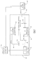
- a NDM 30 would communicate with a DSNX application 32 through line 34, and with a service processor SP application 36 through line 38, and with an I/O platform 40 through line 42.
- a single line 46 is required for transmitting the GDS (general data stream) back and forth between the NDM 30 and the single distributed system 44.
- the modified DSNX application 32' acts as an entry point from the point of view of the network, but in fact it downloads a significant portion of its entry point function to each application through an interface architecture 48. It is important to note that the interface architecture 48 is the same even though the applications 36' and 40' will receive different data objects through the entry point 32'. Thus, multiple applications are able to receive change management data objects over the network through a single entry point which can service one or more sub-entry points.
- a focal point 50 has the usual three SNA facilities provided by the SNA architecture. More specifically, an SNA/DS component 52 uses a communication protocol such as an LU (logical unit type) 6.2 facility 54 in order to exchange data through a SNA/DS network 56 with another LU 6.2 facility 58 and its associated SNA/DS component 60 located at a conventional entry point 61.
- a SNA/FS server 62 in the focal point 50 has a corresponding component 64 at the entry point, while a SNA/MS agent 66 in the focal point 50 has its corresponding component 68 at the entry point.
- the invention provides a unique entry point 70 which is in fact a hybrid.
- the SNA/DS network 56 it appears to be a conventional entry point, having the usual LU 6.2 facility 72 as well as an SNA/DS component 74 for exchanging data with the focal point 50.
- such hybrid entry point 70 has only a partial SNA/FS server 76 and a partial SNA/MS agent 78, with the rest of the required entry point functions handled at sub-entry points 80, 82 each having a partial SNA/FS server and/or partial SNA/MS agent facility 84.
- the invention uses existing SNA protocols for distribution services (DS), file services (FS) and management services (MS) in connection with new protocols used in the interface between a hybrid entry point and multiple sub-entry points.
- DS distribution services
- FS file services
- MS management services
- the result is the off-loading of work from an entry point to a sub-entry point, thereby allowing a sub-entry point to have the same benefits that accrue to a conventional entry point without the need for the full resource and capability required for a conventional entry point.
- partitioning the hybrid entry point's SNA/MS and SNA/FS functions between the hybrid entry point and a sub-entry point there is less resource and capability required at the hybrid entry point.
- an application running at a sub-entry point contains the intelligence and resources needed to handle most of the SNA/MS and SNA/FS functions, while the hybrid entry point handles only the SNA/DS functions and a minimal portion of the SNA/MS and SNA/FS functions.
- any SNA functions not handled at the hybrid entry point are off-loaded to the sub-entry point for processing.
- some additional identifiers are used to facilitate the handshaking and dialog between a hybrid entry point and its sub-entry points, as discussed in more detail below.
- DSNX As the catcher at a hybrid entry point for handling all change management data and commands that come down during a communications session such as LU 6.2 from a control program such as NetView DM (NDM).
- NDM NetView DM
- Other software/hardware facilities can be used to achieve the shared SNA function between a hybrid entry point and its connected sub-entry points, all within the spirit of the invention.
- a communication is sent back through the interface architecture 86 to the hybrid entry point, and a facility such as DSNX would perform the SNA/DS function of communicating the results back up to NDM at the focal point node 50.
- the new sub-entry point interface architecture does not affect the focal point.
- the same focal point resource and communication to an entry point is required whether it is talking to a convention entry point 61 having no sub-entry points or to a hybrid entry point 70 which has sub-entry points 80, 82.
- the focal point always talks directly to the entry point agent, and the focal point does not know whether or not this is a hybrid entry point which is off-loading work to sub-entry point agents.
- sub-entry point applications are not limited to processing microcode. They can be designed to handle almost any kind of object that can be or needs to be handled by an application other than one running at the entry point. It is also important to understand that the new interface architecture is generic enough to be used between any two applications running in an entry point and a sub-entry point.
- a network is shown with a focal point 88 connected through a network to a single remote system 90.
- the remote target system 90 includes a hybrid entry point 92 connected through an SP communication path 94 to a sub-entry point 96 (a service processor), and through a different CPIC (common programming interface communication) communication path 98 to another sub-entry point 100 (an I/O platform).
- a hybrid entry point 102 which provides an APPC (advanced program-to-program communication) communication path 104 to sub-entry point 96. It is noted that the DSNX catcher in hybrid entry point 92 is different from the site server catcher at hybrid entry point 102.
- the same interface architecture 86 is used to provide for intercommunications between an entry point and a sub-entry point. So the new interface architecture is independent of the type of communications path used between an entry point. and its sub-entry points. In other words, we do not rely on the communications path to control the transfer of data.
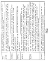
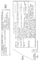
- Figs. 8 and 9 show how an input GDS received by a hybrid entry point is processed, with a subset of the actual input passed to the sub-entry point.
- new interface identifiers 104 are provided to enhance the intercommunications and handshaking between a hybrid entry point and its sub-entry points.
- the catcher at the hybrid entry point is DSNX
- the sub-entry point is a service processor (SP) for a distributed computer system.
- SP service processor
- the processing for an ACCEPT command proceeds as follows.
- the SNA/DS layer provides asynchronous movement of data from one user to one or more other users. This service is provided for distributive service units interconnected by an LU 6.2 conversation. The SP cannot handle LU 6.2 due to lack of resource. Therefore, in this exemplary embodiment, DSNX processes the entire DS layer of an input GDS (generalized data stream).
- the SNA/MS layer provides a change management command. This layer is for the most part handled by the SP.
- the SNA/FS layer provides data object handling instructions but does not deal with the actual command handling. This layer is processed by both DSNX and the SP. For instance in the example shown in Fig. 8, the SP would verify that the "stored canonical name" identifying the data object to accept, does exist. However, the "server request prefix" is verified by DSNX who, acting as the agent, knows that a "decode” instruction is the only valid value for this command.
- Fig. 8 shows how an input GDS for the ACCEPT command would look to DSNX
- Fig. 9 shows how the same ACCEPT command looks to the SP.
- the GDS contains lengths, identifiers and data in a hierarchical fashion as defined by the existing SNA architectures. In the example of Figs. 8 and 9, only major identifiers are shown, and some "child" identifiers have been left off to simplify the example.
- the SP When the processing of the GDS for the ACCEPT command is completed, the SP will provide a subset of the entire output GDA back to DSNX so it can be incorporated in the final GDS report prepared by DSNX for transmission back to the focal point.
- the new identifiers 104 provide additional function to facilitate the processing of the GDS by the SP at the sub-entry point.
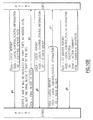
- One such function is the handshaking method for transferring data and for controlling the processing. This handshaking method allows for abort/cancel of transfer data, such as shown in Fig. 11 where an error was found in connection with an INSTALL command. This handshaking method also handles a more complicated transaction such as the SEND command as shown in Fig. 10.
- Another such function is a data control method for the SEND and SEND_AND_INSTALL commands. This data control method allow DSNX to perform command parameter verifications before actually sending the data to the SP.
- Another such function is obtaining network information from the DS layer. Thus, network information is provided in the "network identifiers" vector 106 as indicated in Fig. 9.
- the invention is not limited to the specific interface architecture developed as part of this invention, but to any architected interface which allows a hybrid entry point to offload part of the function to multiple sub-entry points. Nevertheless, it is believed that the hierarchy of new identifiers, as shown on Fig. 12, provide a preferred list of additional function which serve to implement the benefits of the present invention.
Landscapes
- Engineering & Computer Science (AREA)
- Computer Networks & Wireless Communication (AREA)
- Signal Processing (AREA)
- Computer And Data Communications (AREA)
- Multi Processors (AREA)
Applications Claiming Priority (2)
| Application Number | Priority Date | Filing Date | Title |
|---|---|---|---|
| US54360390A | 1990-06-25 | 1990-06-25 | |
| US543603 | 1990-06-25 |
Publications (2)
| Publication Number | Publication Date |
|---|---|
| EP0464352A2 true EP0464352A2 (de) | 1992-01-08 |
| EP0464352A3 EP0464352A3 (en) | 1994-11-17 |
Family
ID=24168736
Family Applications (1)
| Application Number | Title | Priority Date | Filing Date |
|---|---|---|---|
| EP19910108237 Withdrawn EP0464352A3 (en) | 1990-06-25 | 1991-05-22 | Sub-entry point interface architecture for change management in a computer network |
Country Status (3)
| Country | Link |
|---|---|
| US (1) | US6314462B1 (de) |
| EP (1) | EP0464352A3 (de) |
| JP (1) | JP2558020B2 (de) |
Cited By (3)
| Publication number | Priority date | Publication date | Assignee | Title |
|---|---|---|---|---|
| US5625775A (en) * | 1994-06-13 | 1997-04-29 | International Business Machines Corporation | Modem communication interface in a data processing system |
| FR2815155A1 (fr) * | 2000-10-09 | 2002-04-12 | Jacques Rivaillier | Principe et procede pour marquer, identifier et securiser les fichiers informatiques, les documents, les sous, les composes chimiques et appareillages de mise en oeuvre |
| WO2003043000A1 (fr) * | 2001-10-10 | 2003-05-22 | Jacques Rivaillier | Procede pour marquer, identifier et securiser les fichiers informatiques, les documents, les sons et les composes chimiques |
Families Citing this family (6)
| Publication number | Priority date | Publication date | Assignee | Title |
|---|---|---|---|---|
| WO2001046804A1 (en) * | 1999-08-16 | 2001-06-28 | Z-Force Corporation | System of reusable software parts for implementing concurrency and hardware access, and methods of use |
| US7506034B2 (en) * | 2000-03-03 | 2009-03-17 | Intel Corporation | Methods and apparatus for off loading content servers through direct file transfer from a storage center to an end-user |
| US6952737B1 (en) * | 2000-03-03 | 2005-10-04 | Intel Corporation | Method and apparatus for accessing remote storage in a distributed storage cluster architecture |
| US7428540B1 (en) | 2000-03-03 | 2008-09-23 | Intel Corporation | Network storage system |
| US7774325B2 (en) * | 2002-10-17 | 2010-08-10 | Intel Corporation | Distributed network attached storage system |
| US7634559B2 (en) * | 2003-09-11 | 2009-12-15 | Standard Chartered (Ct) Plc | System and method for analyzing network software application changes |
Family Cites Families (4)
| Publication number | Priority date | Publication date | Assignee | Title |
|---|---|---|---|---|
| JPH0756636B2 (ja) * | 1985-12-11 | 1995-06-14 | 株式会社日立製作所 | データ処理方法 |
| JPS63292257A (ja) * | 1987-05-11 | 1988-11-29 | インタ−ナショナル・ビジネス・マシ−ンズ・コ−ポレ−ション | 複数の端末局へのデ−タまたはプログラムのロ−デイング方法 |
| US5084816A (en) * | 1987-11-25 | 1992-01-28 | Bell Communications Research, Inc. | Real time fault tolerant transaction processing system |
| US5089954A (en) * | 1988-08-08 | 1992-02-18 | Bell Communications Research, Inc. | Method for handling conversational transactions in a distributed processing environment |
-
1991
- 1991-05-22 EP EP19910108237 patent/EP0464352A3/en not_active Withdrawn
- 1991-05-24 JP JP3120401A patent/JP2558020B2/ja not_active Expired - Fee Related
-
1997
- 1997-08-13 US US08/910,858 patent/US6314462B1/en not_active Expired - Fee Related
Cited By (3)
| Publication number | Priority date | Publication date | Assignee | Title |
|---|---|---|---|---|
| US5625775A (en) * | 1994-06-13 | 1997-04-29 | International Business Machines Corporation | Modem communication interface in a data processing system |
| FR2815155A1 (fr) * | 2000-10-09 | 2002-04-12 | Jacques Rivaillier | Principe et procede pour marquer, identifier et securiser les fichiers informatiques, les documents, les sous, les composes chimiques et appareillages de mise en oeuvre |
| WO2003043000A1 (fr) * | 2001-10-10 | 2003-05-22 | Jacques Rivaillier | Procede pour marquer, identifier et securiser les fichiers informatiques, les documents, les sons et les composes chimiques |
Also Published As
| Publication number | Publication date |
|---|---|
| JP2558020B2 (ja) | 1996-11-27 |
| JPH076138A (ja) | 1995-01-10 |
| US6314462B1 (en) | 2001-11-06 |
| EP0464352A3 (en) | 1994-11-17 |
Similar Documents
| Publication | Publication Date | Title |
|---|---|---|
| EP0006216B1 (de) | System zur Verarbeitung digitaler Daten | |
| US8788565B2 (en) | Dynamic and distributed queueing and processing system | |
| US5005122A (en) | Arrangement with cooperating management server node and network service node | |
| AU711393B2 (en) | A method and apparatus for client managed flow control on a limited memory computer system | |
| US5608894A (en) | Execution control system | |
| EP0312739B1 (de) | Vorrichtung und Verfahren zur Verbindung von einer Anwendung einer Zugriffseinrichtung für transparente Dienste mit einer entfernt aufgestellten Quelle | |
| US5987502A (en) | Workload management in an asynchronous client/server computer system | |
| EP1230597B1 (de) | Kommunikationsarchitektur für eine verteilte rechnerumgebung | |
| WO1997019411A1 (en) | Registry communications middleware | |
| HK1005347B (en) | An integrated plant environment system having a program-to-program communication server and method | |
| HK1005347A1 (en) | An integrated plant environment system having a program-to-program communication server and method | |
| US6119173A (en) | System and method for communications and process management in a distributed telecommunications switch | |
| US6314462B1 (en) | Sub-entry point interface architecture for change management in a computer network | |
| US20030088661A1 (en) | Method for constructing distributed software components | |
| JP2002108838A (ja) | エージェント実行装置およびエージェント実行方法 | |
| JPH05158850A (ja) | アプリケーション・プログラム間における情報交換システム及び方法 | |
| US8037160B2 (en) | Method and device arrangement for managing a user application/device management server/client device environment | |
| KR20050067413A (ko) | 서비스 통합 시스템을 위한 방법 및 장치 | |
| US6678742B1 (en) | Object-oriented computer system and computer-readable storage medium which stores program | |
| JP2000029847A (ja) | エージェントシステム、情報処理方法及び情報処理用ソフトウェアを記録した記録媒体 | |
| KR102227204B1 (ko) | 분산처리를 적용한 실시간 작업흐름관리 시스템 | |
| CN114884948A (zh) | 一种数据处理系统 | |
| JP3455603B2 (ja) | 通信システム及び非同期通信のイベント制御方法 | |
| Wheeler | Voyager architecture best practices | |
| JPH06274424A (ja) | パケット網に接続可能な情報処理機器 |
Legal Events
| Date | Code | Title | Description |
|---|---|---|---|
| PUAI | Public reference made under article 153(3) epc to a published international application that has entered the european phase |
Free format text: ORIGINAL CODE: 0009012 |
|
| AK | Designated contracting states |
Kind code of ref document: A2 Designated state(s): DE FR GB |
|
| 17P | Request for examination filed |
Effective date: 19911219 |
|
| PUAL | Search report despatched |
Free format text: ORIGINAL CODE: 0009013 |
|
| AK | Designated contracting states |
Kind code of ref document: A3 Designated state(s): DE FR GB |
|
| STAA | Information on the status of an ep patent application or granted ep patent |
Free format text: STATUS: THE APPLICATION HAS BEEN WITHDRAWN |
|
| 18W | Application withdrawn |
Withdrawal date: 19960716 |