EP0463757B1 - Siège pour passager réglable - Google Patents
Siège pour passager réglable Download PDFInfo
- Publication number
- EP0463757B1 EP0463757B1 EP91305156A EP91305156A EP0463757B1 EP 0463757 B1 EP0463757 B1 EP 0463757B1 EP 91305156 A EP91305156 A EP 91305156A EP 91305156 A EP91305156 A EP 91305156A EP 0463757 B1 EP0463757 B1 EP 0463757B1
- Authority
- EP
- European Patent Office
- Prior art keywords
- rail
- plunger
- seating
- cam follower
- lever
- Prior art date
- Legal status (The legal status is an assumption and is not a legal conclusion. Google has not performed a legal analysis and makes no representation as to the accuracy of the status listed.)
- Expired - Lifetime
Links
- 230000033001 locomotion Effects 0.000 claims description 24
- 238000006073 displacement reaction Methods 0.000 claims description 4
- 230000008878 coupling Effects 0.000 claims description 3
- 238000010168 coupling process Methods 0.000 claims description 3
- 238000005859 coupling reaction Methods 0.000 claims description 3
- 230000015572 biosynthetic process Effects 0.000 claims 2
- 210000001364 upper extremity Anatomy 0.000 description 8
- 230000010006 flight Effects 0.000 description 3
- 238000010276 construction Methods 0.000 description 1
- 238000009434 installation Methods 0.000 description 1
- 238000000034 method Methods 0.000 description 1
Images


Classifications
-
- B—PERFORMING OPERATIONS; TRANSPORTING
- B60—VEHICLES IN GENERAL
- B60N—SEATS SPECIALLY ADAPTED FOR VEHICLES; VEHICLE PASSENGER ACCOMMODATION NOT OTHERWISE PROVIDED FOR
- B60N2/00—Seats specially adapted for vehicles; Arrangement or mounting of seats in vehicles
- B60N2/24—Seats specially adapted for vehicles; Arrangement or mounting of seats in vehicles for particular purposes or particular vehicles
- B60N2/242—Bus seats
-
- B—PERFORMING OPERATIONS; TRANSPORTING
- B64—AIRCRAFT; AVIATION; COSMONAUTICS
- B64D—EQUIPMENT FOR FITTING IN OR TO AIRCRAFT; FLIGHT SUITS; PARACHUTES; ARRANGEMENT OR MOUNTING OF POWER PLANTS OR PROPULSION TRANSMISSIONS IN AIRCRAFT
- B64D11/00—Passenger or crew accommodation; Flight-deck installations not otherwise provided for
- B64D11/06—Arrangements of seats, or adaptations or details specially adapted for aircraft seats
- B64D11/0696—Means for fastening seats to floors, e.g. to floor rails
Definitions
- This invention relates to adjustable passenger seating arrangement for vehicles, particularly aircraft, of the type comprising a floor-mounted seat rail adapted to extend longitudinally through at least a portion of a passenger carrying compartment and at least three seating units mounted on said seat rail; each seating unit comprising a number of seats; the seat rail including a series of equally spaced interconnected openings along its length for fixedly engaging and retaining the seating units at any selected lengthwise location; at least one of the seating units includes seat adjustment means comprising a plunger for engaging in said rail mounted on a leg of said seating unit for vertical movement between a rail-engaging position in which it engages with the rail to restrain fore and aft movement and a release position in which it permits fore and aft movement of the seating unit, a foot for engaging in said rail so as to resist both fore and aft movement and vertical movement, and a lever pivotally mounted on the foot.
- An arrangement of this type is disclosed in EP-A-0215495.
- the seating unit can be secured in any one of a
- the present invention aims to provide a seating system having means for moving a seat structure in the fore and aft direction between two predetermined positions, without the need to select the required position from a multiplicity of closely adjacent possible positions.
- the lever has a cam follower engaging in vertically extending guide means secured to the seating unit, and coupling means responsive to displacement of the cam follower is adapted to move the plunger to its release position when the cam follower moves from the bottom of the guide means and to return the plunger to its engaged position when the cam follower returns to the bottom of the guide means.
- the cam follower is positionable at the bottom of the guide means either when the seating unit is in a first position in which the lever projects forwardly from the foot or when the seating unit is in a second position in which the lever projects rearwardly from the foot.
- the distance between these two positions is arranged to be a multiple of the spacing between the openings in the rail so that the plunger can move into its engaged position when the seating unit is in either of these two positions.
- the lever may be provided with manually operable means, for example a detachable lever for causing pivotal movement relative to the plunger.
- Figure 1 shows a portion of an aircraft passenger cabin having a floor 10, a ceiling 12 and three two-seat seating units 14, 16 and 18.
- the seating unit 16 has two side frames, each comprising a front leg 20, and a rear leg 22, the two frames being interconnected by a transverse member 24.
- Each of the side frames is aligned with a respective seat rail mounted in the floor 10.
- the construction of each seat rail and the manner of attachment of the seat units thereto is well known and is described, for example, in US-A-4856738.
- each seat rail 30 includes a longitudinal extending guideway slot 32. Throughout the length of the rail 30, equally spaced holes 34 extend vertically between the guideway slot and the seat rail upper surface 36, and longitudinal slots 38 interconnect the vertical holes 34.
- the slot 38 and the guideway slot 32 are configured to conform substantially to the shoulder portion 40 of an attachment stud 42 which protrudes from each back leg 22 of the seating unit 16, and the holes 34 are of clearance diameter to accommodate the stud shoulder 40.
- a similar stud projects from each front leg.
- the seat rail further includes side flanges 44 for seating floor panels 46 and a vertical flange 48 for attachment to a structural member 50 of the aircraft.
- the holes 34 are equally spaced at one inch pitch and the studs on each seat unit are appropriately spaced to ensure conformity with the rail.
- To install and positively engage the seat on the rail it is positioned at its desired fore and aft location such that the studs 42 locate in the corresponding holes 34, stud face 52 seating on the lower surface 54 of the guideway slot 32. Once positioned, the seat is moved forwards or rearwards as required until the shoulder surface 56 engages under the lip 58, that is at an intermediate position between two adjacent holes 34, resulting in positive engagement of the seat as indicated in Figure 11.
- this method of connecting seats to floor rails is well known and does not form part of the present invention.
- Figure 4 shows the stud 42 on the bottom of the leg 20 in engagement with the rail 30.
- a plunger 60 which is vertically movable relative to the leg 22 between an engaged positions (illustrated) and a release position.
- the engaged position it engages in the hole 34 immediately in front of the stud 42 so as to block movement of the stud 42 along the rail 30.
- the release position the plunger 60 is lifted clear of the rail 30, thereby freeing the stud 42 to slide.
- the plunger 60 is coupled by a bell crank lever 62 to a slider 64 which is mounted on a frame member 66 of the seating unit 16, the frame member 66 extending between the bottom of the rear leg 22 and the bottom of the corresponding front leg 20.
- a screw 68 projects through a slot 70 in the slider 64 and engages in the frame member 66 so as to permit this sliding movement.
- the bell crank 62 is mounted on a pivot pin 72 at the rear end of the member 66.
- a second stud 80 also engages in the rail.
- the stud 80 is connected to a bracket 82 which has a plunger 84, similar to the plunger 60 in that it is vertically movable relative to the bracket 82.
- the plunger 84 is spring-biassed into its engaged position, as illustrated in Figure 4 and can be displaced upwardly by means (not shown) to permit complete removal of the seating unit 16 from the aircraft. In normal use, once installed, the plunger 84 is permanently left in its engaged position.
- a lever 86 has one end pivotally coupled to the bracket 82. At its other end, the lever 86 carries a cam follower stud 88 which engages in a slot 90 in a vertical member 92 extending between the base member 66 and the leg 20. In its upper edge, the slider 64 has an open ended slot 96 which receives the cam follower stud 88 and the upper end of which is inclined rearwardly.
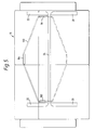
- the lever 86 has a socket 98 which detachably receives a handle 100. As can be seen from Figure 5, the handle 100 extends across the seat so as to engage with a similar lever 102 associated with the leg 22 on the other side, and has a central hand grip 104.
- the handle 100 When it is desired to move the seat 16 from the position shown in solid lines in Figure 1 to the position shown in dotted lines, the handle 100 is moved in a clockwise direction about the pivot point of the lever 86 on the bracket 82, raising the cam follower stud 88. As the stud 88 disengages from the slot 96 in the slider 64, it displaces the latter to the left, as viewed in Figure 4, so that the bell crank lever 62 raises the plunger 60 out of engagement with the rail 30.
- the backrest of the seat 16 can be inclined almost to the horizontal, so that it lies on the seat cushion of the seat 18, and there is much more leg room between the seat 16 and the seat 14. Consequently, although the seat 18 cannot be occupied, the occupant of the seat 16 can be charged a higher fare in view of the more comfortable sleeping position provided by the invention.
- lever 100 When it is desired to return the aircraft to its full-capacity daytime condition, the lever 100 is pivoted back to the position illustrated in Figure 4.
- the lever 100 is detachable. Preferably, it is removed when the aircraft is in use so as to leave unobstructed baggage storage space under the seats.
- the bell crank lever 62 may be replaced by a cam system.
- FIGS 7 and 8 illustrate another embodiment of the invention comprising a seating unit having two side frames, each comprising a front leg 110, a rear leg 112 and a diagonal brace 114 interconnecting the top of the rear leg 112 and the bottom of the front leg 110.
- the two side frames are interconnected by a first transverse member 116 at the top of the front legs 110 and a rear transverse 118 at the top of the rear legs 112.
- each of the side frames is aligned with a respective seat rail mounted in the aircraft floor, as illustrated in Figures 1 to 3.
- the bottom of the rear leg 112 carries two studs 118 and 120 which are similar to the stud 42 of Figure 1 and which are spaced apart from one another by a distance equal to the spacing between the holes 34 in the seat rails 30 (see Figure 3).
- a T-shaped skid pad 122 is secured to the stems of the studs 118 and 120 so that its stem projects into the slot 32 in the seat rail 30 and its cross-bar rests on the rail upper surface 36.
- the bottom of the front leg 110 carries a similar stud 124.
- a similar T-shaped skid pad 126 is slidably mounted on the shank of the stud 124 and biassed downwardly by Bellville washers 128.
- the bottoms of the front leg 110 and rear leg 112 are interconnected by a frame member 130, similar to the frame member 66 of Figures 4 to 6.
- a slider 132 similar to the slider 64, is mounted in slide guides 134 and 136 which are secured to the frame member 130.
- the slide guide 136 in the aisle-side frame carries a plunger 138 which is spring biassed into a hole in the slider 132 so as to lock the latter in position, as will be explained hereinafter.
- the rear end of the slider 32 is pivotally coupled to one arm of a bell-crank lever 140, which is journalled on a pivot pin 142 mounted on the frame member 130 and which has its other arm pivotally coupled to a plunger 144 which is dimensioned to engage in one of the holes 34 of the rail 30 in a similar manner to the plunger 60 of Figures 4 to 6.
- a further pair of studs 150 and 152 also engage with the rail 30.
- the studs 150 and 152 are mounted on a bracket 154 which also carries a plunger 156 which is vertically movable relative to the bracket 154 into and out of engagement with the rail to permit complete removal of the seating unit from the aircraft.
- the plunger 156 is permanently secured in its engaged position by a clamping screw 157.
- the arrangement is thus similar to that of the plunger 84 of Figures 4 to 6.
- a lever 158 On each side frame, a lever 158, similar to the lever 86 of Figures 4 to 6, has one end pivotally coupled to the bracket 154. At its other end, the lever 158 carries a cam follower stud 160 which engages in a slot 162 in a vertical member 164 extending between the frame member 130 and the diagonal brace 114.
- the front end of the slider 132 has an open-ended slot 166 in its upper edge (similar to the slot 96 of Figures 4 to 6) which receives the cam follower stud 88.
- Angular movement of the levers 158 between the position shown in Figure 7 and the position shown in Figure 8 moves the seat unit between a forward position, corresponding to the position of the seat 16 shown in solid lines in Figure 1, to a rearward position similar to the position of the seat unit 16 shown in dotted lines in Figure 1.
- the means for effecting angular movement of the levers 158 differs from that illustrated in Figures 4 to 6.
- the two levers 158 are interconnected at their lower ends by a torque rod 170 which extends across the bottom of the seat under the aircraft floor carpet.
- the torque rod 170 is secured fast with the levers 158 and is journalled in the brackets 156.
- the torque rod 170 At its end facing the aircraft aisle, the torque rod 170 has flat surfaces 172 which can be engaged by a detachable tool to effect the necessary angular movement.
- the spring loaded plunger 138 it is necessary to raise the spring loaded plunger 138 so as to disengage its bottom end from the recess in the slider 132.
Landscapes
- Engineering & Computer Science (AREA)
- Aviation & Aerospace Engineering (AREA)
- Transportation (AREA)
- Mechanical Engineering (AREA)
- Seats For Vehicles (AREA)
Claims (7)
- Siège pour passager réglable, destiné à être utilisé dans un véhicule de transport de passagers, comprenant un rail de siège (20) monté sur le plancher, adapté de façon à s'étendre longitudinalement dans au moins une partie du compartiment des passagers et au moins trois ensembles de siège (14, 16, 18) montés sur ledit rail de siège (30); chaque ensemble de siège comprenant un certain nombre de sièges; le rail de siège (30) comprenant sur sa longueur une série d'ouvertures (34) interconnectées, espacées de façon égale, destinées à entrer en prise et à maintenir rigidement les ensembles de siège (14, 16, 18) en tout emplacement sélectionné sur la longueur; au moins l'un des ensembles de siège (14, 16, 18) comprend un moyen de réglage de siège comportant un piston (60, 144) destiné à venir en prise dans ledit rail (30) monté sur un jambage (22, 112) dudit ensemble de siège, afin de pouvoir se déplacer verticalement entre une position engagée en prise avec le rail, dans laquelle il vient en prise du rail (30) afin d'empêcher tout déplacement avant-arrière et une position de libération, dans laquelle il permet le déplacement avant-arrière de l'ensemble de siège (16), un pied (80, 82, 84, 150, 152, 154, 156) destiné à entrer en prise dans ledit rail (30), de manière à résister à la fois à un déplacement avant-arrière et à un déplacement vertical, et un levier (86, 158) monté pivotant sur le pied (80, 82, 84, 150, 152, 154, 156), caractérisé en ce que le levier (86, 158) présente un suiveur de came (88, 160) s'engageant en prise dans un moyen de guidage (90, 162) s'étendant verticalement, fixé à l'ensemble de siège (16), et un moyen de couplage (64, 132) sensible au déplacement du suiveur de came (88, 160) est adapté de façon à déplacer le piston (60, 144) vers sa position de libération lorsque le suiveur de came (88, 160) se déplace depuis le fond du moyen de guidage (90, 162) et à ramener le piston (60, 144) vers sa position engagée en prise, lorsque le suiveur de came (88, 160) retourne vers le fond du moyen de guidage (90, 162).
- Siège réglable selon la revendication 1, dans lequel le suiveur de came (88, 160) peut être disposé au fond du moyen de guidage (90, 162), soit lorsque l'ensemble de siège (16) se situe dans une première position, dans laquelle le levier (86, 158) fait saillie vers l'avant depuis le pied, soit lorsque l'ensemble de siège (16) se situe dans une deuxième position, dans laquelle le levier (86, 158) fait saillie vers l'arrière depuis le pied, la distance entre ces deux positions étant un multiple de l'espacement entre les ouvertures (34) ménagées dans le rail (30), de manière que le piston (60, 144) puisse se déplacer vers sa position engagée lorsque l'ensemble de siège (16) se situe dans l'une de ces deux positions.
- Siège réglable selon la revendication 2, dans lequel le levier (86, 158) est pourvu de moyens (100, 172) pouvant être actionnés manuellement, afin de provoquer un mouvement pivotant par rapport au piston (60, 144).
- Siège réglable selon la revendication 3, dans lequel le moyen pouvant être actionné manuellement comprend un levier amovible (100).
- Siège réglable selon l'une quelconque des revendications précédentes, dans lequel le moyen de couplage sensible au déplacement du suiveur de came (88, 160) comprend un coulisseau (64, 132) déplaçable horizontalement, présentant une formation de came (96, 166) à une extrémité et un moyen (62, 140) relié au piston (60, 144) à son autre extrémité.
- Siège réglable selon la revendication 5, dans lequel ledit moyen relié au piston (60, 144) comprend un levier coudé (62, 140).
- Siège réglable selon la revendication 5, dans lequel ladite formation de came comprend une fente à extrémité ouverte (96, 166), le suiveur de came (88, 160) étant adapté de façon à provoquer un déplacement dudit coulisseau (64, 132) durant un déplacement initial verts le haut du suiveur de came (88, 160), depuis le fond du moyen de guidage (90, 162) et à sortir de ladite fente à extrémité ouverte (96, 166) durant un déplacement subséquent vers le haut, pendant lequel l'entrée en prise du suiveur de came (88, 160) avec le moyen de guidage (90, 162) provoque un déplacement de l'ensemble de siège (16) le long de la voie (30).
Applications Claiming Priority (2)
| Application Number | Priority Date | Filing Date | Title |
|---|---|---|---|
| GB9013717 | 1990-06-20 | ||
| GB909013717A GB9013717D0 (en) | 1990-06-20 | 1990-06-20 | Adjustable passenger seating arrangement |
Publications (3)
| Publication Number | Publication Date |
|---|---|
| EP0463757A2 EP0463757A2 (fr) | 1992-01-02 |
| EP0463757A3 EP0463757A3 (en) | 1992-09-16 |
| EP0463757B1 true EP0463757B1 (fr) | 1994-11-02 |
Family
ID=10677896
Family Applications (1)
| Application Number | Title | Priority Date | Filing Date |
|---|---|---|---|
| EP91305156A Expired - Lifetime EP0463757B1 (fr) | 1990-06-20 | 1991-06-07 | Siège pour passager réglable |
Country Status (4)
| Country | Link |
|---|---|
| US (1) | US5183313A (fr) |
| EP (1) | EP0463757B1 (fr) |
| DE (1) | DE69104913T2 (fr) |
| GB (1) | GB9013717D0 (fr) |
Cited By (1)
| Publication number | Priority date | Publication date | Assignee | Title |
|---|---|---|---|---|
| DE19547095A1 (de) * | 1995-12-16 | 1997-06-19 | Waggonfabrik Talbot Gmbh & Co | Variable Befestigungsanordnung für Elemente einer Innenausstattung |
Families Citing this family (33)
| Publication number | Priority date | Publication date | Assignee | Title |
|---|---|---|---|---|
| DE4431248C1 (de) * | 1994-09-02 | 1995-08-17 | Daimler Benz Ag | Ausbaubarer Rücksitz für Kraftfahrzeuge |
| GB9425078D0 (en) | 1994-12-13 | 1995-02-08 | British Airways Plc | A seating unit |
| GB2314012B (en) * | 1996-06-13 | 1999-01-13 | Michael Angelo Callard | A removable seat |
| GB2341088B (en) * | 1996-07-10 | 2000-05-03 | Safety Systems Ltd Nmi | A carriage slidably and removably mounted on a track |
| GB9618659D0 (en) * | 1996-09-06 | 1996-10-16 | Univ Manchester Metropolitan | Seating system |
| US5913559A (en) * | 1997-03-19 | 1999-06-22 | Ferno-Washington, Inc. | Fastening track, cot transport vehicle adapted to secure the fastening track, and cot fastening system incorporating same |
| US5871318A (en) * | 1997-11-12 | 1999-02-16 | Be Aerospace, Inc. | Quick-release track fastener |
| GB2347619B (en) * | 1999-03-10 | 2002-11-13 | Nmi Safety Systems Ltd | Improvements in or relating to a seat support |
| EP2272711B2 (fr) | 2001-08-09 | 2015-07-01 | Virgin Atlantic Airways Limited | Système de sièges et unité d'accueil de passagers pour véhicule |
| US6913317B2 (en) * | 2002-06-25 | 2005-07-05 | Telescope Casual Furniture, Inc. | Adjustable swivel rocker |
| US20050106267A1 (en) | 2003-10-20 | 2005-05-19 | Framework Therapeutics, Llc | Zeolite molecular sieves for the removal of toxins |
| US6902365B1 (en) | 2004-02-13 | 2005-06-07 | B E Aerospace, Inc. | Quick-release track fastener |
| FR2866315B1 (fr) * | 2004-02-13 | 2007-04-20 | Airbus France | Rail de siege pour cabine d'aeronef et procede de fabrication d'un tel rail |
| US7029215B2 (en) * | 2004-02-13 | 2006-04-18 | Be Aerospace, Inc. | Dual track fitting |
| US7393167B2 (en) * | 2005-05-17 | 2008-07-01 | Be Aerospace, Inc. | Load-limiting and energy-dissipating mount for vehicle seating |
| DE102005049187A1 (de) * | 2005-10-14 | 2007-04-19 | Recaro Aircraft Seating Gmbh & Co. Kg | Sitzbefestigungsvorrichtung |
| DE102005054890B4 (de) | 2005-11-17 | 2014-08-21 | Airbus Operations Gmbh | Flugzeugrumpfstruktur mit einer Passagierkabine und einer Befestigungsstruktur zur Fixierung von Inneneinrichtungskomponenten in der Passagierkabine |
| CA2634914C (fr) | 2005-12-23 | 2014-04-08 | British Airways Plc | Siege de passager d'aeronef |
| EP1978845B1 (fr) * | 2006-01-30 | 2015-08-12 | BE Aerospace, Inc. | Fixation anti-cliquetis à une glissière |
| FR2948632B1 (fr) * | 2009-07-28 | 2011-08-26 | Attax | Systeme d'accrochage d'un siege d'aeronef |
| FR2969232B1 (fr) * | 2010-12-21 | 2013-01-04 | Sagem Defense Securite | Organe d'attache d'un bati a une glissiere et bati equipe d'un tel organe d'attache |
| US9714862B2 (en) | 2011-10-07 | 2017-07-25 | Bombardier Inc. | Aircraft seat |
| DE102012012686B4 (de) * | 2012-06-27 | 2014-12-11 | Airbus Defence and Space GmbH | Luftfahrzeug mit einer Anzahl Reihen von in Fahrzeuglängsrichtung hinter einander angeordneter Sitzanordnungen mit längsverschiebbaren Sitzreihen, Sitzanordnung und deren Verwendung |
| US20150145300A1 (en) * | 2013-11-27 | 2015-05-28 | B/E Aerospace, Inc. | Method and apparatus for adjusting the spacing of vehicle seats based on the size of the seat occupant |
| EP2923946B1 (fr) | 2014-03-28 | 2018-05-30 | Airbus Operations GmbH | Agencement de siège passager pour véhicule |
| US9919803B2 (en) | 2014-04-04 | 2018-03-20 | B/E Aerospace, Inc. | Aircraft seat base frame |
| US9573688B2 (en) * | 2014-04-04 | 2017-02-21 | B/E Aerospace, Inc. | Aircraft seat base frame |
| WO2016049356A1 (fr) * | 2014-09-25 | 2016-03-31 | Bombardier Inc. | Siège d'aéronef |
| DE102016110057A1 (de) * | 2016-05-31 | 2017-11-30 | Airbus Operations Gmbh | Passagiersitzsystem für eine Kabine eines Transportmittels |
| US10737601B2 (en) * | 2016-07-18 | 2020-08-11 | Safran Seats Usa Llc | Seat beam clamp |
| EP3323725B1 (fr) * | 2016-11-16 | 2020-08-12 | Airbus Operations GmbH | Kit de siège d'aéronef, agencement de cabine et de siège d'aéronef avec différents types d'adaptateurs de rail de siège |
| US11427328B2 (en) | 2019-03-29 | 2022-08-30 | The Boeing Company | Seat indexing systems and methods |
| US10967760B2 (en) * | 2019-04-04 | 2021-04-06 | Volvo Car Corporation | Lightweight c-ring crossmember and bracket assembly for a vehicle |
Family Cites Families (10)
| Publication number | Priority date | Publication date | Assignee | Title |
|---|---|---|---|---|
| US1735518A (en) * | 1927-01-03 | 1929-11-12 | Paralock Company | Vehicle seat |
| US3620171A (en) * | 1969-12-04 | 1971-11-16 | Ancra Corp | Rattleproof tie-down assembly |
| US3605637A (en) * | 1970-09-02 | 1971-09-20 | Ancra Corp | Anchor fitting for securing loads to a retainer track |
| US4114947A (en) * | 1977-11-18 | 1978-09-19 | Chas. Olson & Sons | Detachable seat mounting for buses |
| US4277043A (en) * | 1979-05-25 | 1981-07-07 | Koehler-Dayton, Inc. | Locking assembly for aircraft seat |
| FR2458462A1 (fr) * | 1979-06-06 | 1981-01-02 | Tissmetal Lionel Dupont | Dispositif de variation du pas des sieges dans les avions commerciaux |
| US4396175A (en) * | 1980-12-08 | 1983-08-02 | Uop Inc. | Track fitting |
| US4936527A (en) * | 1985-09-12 | 1990-06-26 | The Boeing Company | Movable seating system for aircraft |
| US4723732A (en) * | 1985-09-12 | 1988-02-09 | The Boeing Company | Movable seating system for aircraft |
| GB8705393D0 (en) * | 1987-03-07 | 1987-04-08 | British Aerospace | Seating arrangement for aircraft |
-
1990
- 1990-06-20 GB GB909013717A patent/GB9013717D0/en active Pending
-
1991
- 1991-06-07 DE DE69104913T patent/DE69104913T2/de not_active Expired - Fee Related
- 1991-06-07 EP EP91305156A patent/EP0463757B1/fr not_active Expired - Lifetime
- 1991-06-10 US US07/713,112 patent/US5183313A/en not_active Expired - Lifetime
Cited By (2)
| Publication number | Priority date | Publication date | Assignee | Title |
|---|---|---|---|---|
| DE19547095A1 (de) * | 1995-12-16 | 1997-06-19 | Waggonfabrik Talbot Gmbh & Co | Variable Befestigungsanordnung für Elemente einer Innenausstattung |
| DE19547095C2 (de) * | 1995-12-16 | 2003-06-26 | Talbot Gmbh & Co Kg | Variable Befestigungsanordnung für Elemente einer Innenausstattung |
Also Published As
| Publication number | Publication date |
|---|---|
| GB9013717D0 (en) | 1990-08-08 |
| DE69104913T2 (de) | 1995-03-23 |
| EP0463757A3 (en) | 1992-09-16 |
| US5183313A (en) | 1993-02-02 |
| DE69104913D1 (de) | 1994-12-08 |
| EP0463757A2 (fr) | 1992-01-02 |
Similar Documents
| Publication | Publication Date | Title |
|---|---|---|
| EP0463757B1 (fr) | Siège pour passager réglable | |
| EP0530923B1 (fr) | Installation de sièges pour avion | |
| EP0825060B1 (fr) | Siège de véhicule | |
| US5425516A (en) | Aircraft passenger accomodation system | |
| EP1116654B1 (fr) | Siège de passagers transformable en couchette | |
| US4512609A (en) | Arrangement in a vehicle seat | |
| US5145232A (en) | Seat for vehicles, particularly motor cars | |
| US10583926B2 (en) | Aircraft seat | |
| US6669295B2 (en) | Passenger seat with low profile seat back recline locking assembly | |
| US6644738B2 (en) | Aircraft passenger seat frame construction | |
| US4394047A (en) | Seat back mounting system | |
| EP0282244B1 (fr) | Réglage de la disposition des sièges d'un avion | |
| EP0294086B1 (fr) | Sièges réglables en largeur pour véhicules de transport | |
| AU671382B2 (en) | Armrest arrangements in convertible aircraft passenger seating | |
| US20030075962A1 (en) | Vehicle seat, especially for aircraft | |
| EP0530920A1 (fr) | Installation de sièges pour avion | |
| US20030094840A1 (en) | Locking collar for passenger seat back recline assembly | |
| US20030094542A1 (en) | Passenger seat, passenger seat leg module and method | |
| GB2273088A (en) | Aircraft cabin divider | |
| US5288134A (en) | Seat assembly with integrated seat cushion and seat track frame | |
| DE69925978T2 (de) | Vorrichtung zur Bereitstellung eines Privatsphärenschutzes und eine Unterstützung für Passagiere in der Kabine eines Verkehrsflugzeugs | |
| US3880466A (en) | Forward-folding arm rest for vehicular seating | |
| WO1995029843A1 (fr) | Accoudoirs de rangees transformables en deux ou trois sieges pour passagers d'avion | |
| US5383704A (en) | Intermediate armrest for a row of seats | |
| US4601455A (en) | Combination memory and safety stops for seats |
Legal Events
| Date | Code | Title | Description |
|---|---|---|---|
| PUAI | Public reference made under article 153(3) epc to a published international application that has entered the european phase |
Free format text: ORIGINAL CODE: 0009012 |
|
| AK | Designated contracting states |
Kind code of ref document: A2 Designated state(s): DE FR GB IT |
|
| PUAL | Search report despatched |
Free format text: ORIGINAL CODE: 0009013 |
|
| AK | Designated contracting states |
Kind code of ref document: A3 Designated state(s): DE FR GB IT |
|
| 17P | Request for examination filed |
Effective date: 19921103 |
|
| 17Q | First examination report despatched |
Effective date: 19940117 |
|
| GRAA | (expected) grant |
Free format text: ORIGINAL CODE: 0009210 |
|
| AK | Designated contracting states |
Kind code of ref document: B1 Designated state(s): DE FR GB IT |
|
| ITF | It: translation for a ep patent filed | ||
| REF | Corresponds to: |
Ref document number: 69104913 Country of ref document: DE Date of ref document: 19941208 |
|
| ET | Fr: translation filed | ||
| PLBE | No opposition filed within time limit |
Free format text: ORIGINAL CODE: 0009261 |
|
| STAA | Information on the status of an ep patent application or granted ep patent |
Free format text: STATUS: NO OPPOSITION FILED WITHIN TIME LIMIT |
|
| 26N | No opposition filed | ||
| REG | Reference to a national code |
Ref country code: GB Ref legal event code: IF02 |
|
| PGFP | Annual fee paid to national office [announced via postgrant information from national office to epo] |
Ref country code: GB Payment date: 20050520 Year of fee payment: 15 |
|
| PGFP | Annual fee paid to national office [announced via postgrant information from national office to epo] |
Ref country code: FR Payment date: 20050523 Year of fee payment: 15 |
|
| PGFP | Annual fee paid to national office [announced via postgrant information from national office to epo] |
Ref country code: DE Payment date: 20050822 Year of fee payment: 15 |
|
| PG25 | Lapsed in a contracting state [announced via postgrant information from national office to epo] |
Ref country code: GB Free format text: LAPSE BECAUSE OF NON-PAYMENT OF DUE FEES Effective date: 20060607 |
|
| PGFP | Annual fee paid to national office [announced via postgrant information from national office to epo] |
Ref country code: IT Payment date: 20060630 Year of fee payment: 16 |
|
| PG25 | Lapsed in a contracting state [announced via postgrant information from national office to epo] |
Ref country code: DE Free format text: LAPSE BECAUSE OF NON-PAYMENT OF DUE FEES Effective date: 20070103 |
|
| GBPC | Gb: european patent ceased through non-payment of renewal fee |
Effective date: 20060607 |
|
| REG | Reference to a national code |
Ref country code: FR Ref legal event code: ST Effective date: 20070228 |
|
| PG25 | Lapsed in a contracting state [announced via postgrant information from national office to epo] |
Ref country code: FR Free format text: LAPSE BECAUSE OF NON-PAYMENT OF DUE FEES Effective date: 20060630 |
|
| PG25 | Lapsed in a contracting state [announced via postgrant information from national office to epo] |
Ref country code: IT Free format text: LAPSE BECAUSE OF NON-PAYMENT OF DUE FEES Effective date: 20070607 |