EP0463744A2 - Antivol pour roues de véhicules automobiles - Google Patents
Antivol pour roues de véhicules automobiles Download PDFInfo
- Publication number
- EP0463744A2 EP0463744A2 EP91304908A EP91304908A EP0463744A2 EP 0463744 A2 EP0463744 A2 EP 0463744A2 EP 91304908 A EP91304908 A EP 91304908A EP 91304908 A EP91304908 A EP 91304908A EP 0463744 A2 EP0463744 A2 EP 0463744A2
- Authority
- EP
- European Patent Office
- Prior art keywords
- key
- casing
- lock cylinder
- annular
- theft device
- Prior art date
- Legal status (The legal status is an assumption and is not a legal conclusion. Google has not performed a legal analysis and makes no representation as to the accuracy of the status listed.)
- Granted
Links
Images
Classifications
-
- E—FIXED CONSTRUCTIONS
- E05—LOCKS; KEYS; WINDOW OR DOOR FITTINGS; SAFES
- E05B—LOCKS; ACCESSORIES THEREFOR; HANDCUFFS
- E05B9/00—Lock casings or latch-mechanism casings ; Fastening locks or fasteners or parts thereof to the wing
- E05B9/08—Fastening locks or fasteners or parts thereof, e.g. the casings of latch-bolt locks or cylinder locks to the wing
- E05B9/084—Fastening of lock cylinders, plugs or cores
- E05B9/086—Fastening of rotors, plugs or cores to an outer stator
Definitions
- the invention relates to an anti-theft device for motor vehicle wheels.
- An anti-theft device for motor vehicle wheels comprising a casing covering the polygonal head of a wheel nut or bolt in which there is rotatably arranged a lock cylinder of which the tumblers projecting beyond the surface of the lock cylinder and entering annular grooves on the internal wall of the polygonal head in the anti-theft position can be adjusted into a position retracted from the annular grooves by insertion of the key is known from DE 30 17 630 A1.
- the key has a projection which lies in the plane of the key channel and passes behind an annular shoulder at the end face of the casing when the key is inserted and turned from the basic position, this casing trapping the key against withdrawal and forming a transverse slot for the passage of the projection.
- the annular shoulder on the end face of the casing is formed by a spring washer which is clipped in an annular groove of the casing and forms the transverse slot for the passage of the projection.
- This spring washer is also used to surround the larger diameter collar of the lock cylinder and to prevent it from being withdrawn from the casing.
- the present invention provides an anti-theft device for motor vehicle wheels which device comprises a casing covering the polygonal head of a wheel nut or bolt in which there is rotatably arranged a lock cylinder the tumblers of which project beyond the surface of the lock cylinder and enter annular grooves on the internal wall of the polygonal head in the anti-theft position, and can be adjusted into a position retracted from the annular grooves by insertion of the key, the key having a projection which lies in the plane of the key channel and passes behind an annular shoulder at the end face of the casing when the key is inserted and turned from the basic position, this casing trapping the key against withdrawal and forming a transverse slot for the passage of the projection, characterised in that at least one projecting catch is shaped on the lock cylinder and passes behind the annular shoulder covering an annular groove of the casing into which the projection of the key projects.
- the projecting catch is preferably guided through the transverse slot into its engagement position, and is more preferably formed by two fork-shaped wings which are radial to the lock cylinder and after being inserted through the transverse slot are spread apart in the circumferential direction owing to their elastic restoring force into the engagement position of the shoulder and project into the annular groove.
- This construction results in an anti-theft device for motor vehicle wheels which can be produced at low cost and is simple to manage. No additional components are required for holding the lock cylinder when inserted in the casing. However, the rotatability of the lock cylinder relative to the casing is ensured.
- the transverse slot of the annular shoulder on the end face of the casing serves not only for the passage of the key projection but also for the guidance of at least one projecting catch moulded to the lock cylinder. After the projecting catch has passed through the transverse slot, which takes place as the casing and lock cylinder are assembled, the projecting catch passes behind the annular shoulder into the annular groove covered thereby.
- a backward shift of the lock cylinder is no longer possible, creating an irreversible connection between the casing and the lock cylinder in the axial direction, this connection nevertheless allowing relative rotation of the two parts.
- the position in which the key channel is not aligned with the transverse slot of the annular shoulder can arise when the casing is placed onto the polygonal head of a wheel nut or bolt and the key is removed.
- the lock cylinder can then be turned by the key tip such that orientation of the key channel coincides with the transverse slot, in which position the projection can travel through the transverse slot during continued insertion of the key in order to engage with the annular shoulder after a certain closing turn.
- the projecting catch comprises two fork-shaped wings extending radially to the lock cylinder.
- the wings can, to a certain extent, yield during insertion and, after travelling through the slot, are spread apart in the circumferential direction owing to their elastic restoring force into the engagement position of the shoulder and project into the annular groove and remain therein.
- the ramps of the wings provide assistance so that, as the wings are inserted through the transverse slot, they are continuously squeezed together. Deformation of the wings is therefore substantially avoided. It is particularly advisable to provide two diametrically opposed pairs of wings orientated transversely to the key channel and two appropriately opposing slots on the end face of the casing.
- the outwardly spring-loaded tumblers can enter the spaces between the saw-teeth, i.e. the annular grooves, to secure the axial situation of the lock cylinder with the casing, this position still allowing rotation of the casing.
- the casing embraces the polygonal head, it is not possible to apply a spanner etc. It can only be applied after appropriate removal of the casing.
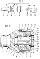
- Figure 1 shows a wheel bolt, a casing containing the lock cylinder and the associated key side by side.
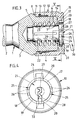
- Figure 2 is a greatly enlarged view of a longitudinal central section through the assembled device.
- Figure 3 is a view corresponding to Figure 2 but with the key inserted into the key channel of the lock cylinder, the tumblers being pulled back into a release position relative to the annular grooves of the wheel bolt.
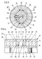
- Figure 4 shows a front view of the casing corresponding to the position in Figure 2 but with the key indicated in dot dash lines.
- Figure 5 shows the section along the line V-V in Figure 3, with the difference from this figure that the lock cylinder is rotated through about 90° by the key.
- Figure 6 is a greatly enlarged view of the section along the line VI-VI, illustrating the engagement position of two fork-shaped wings forming a projecting catch.
- the anti-theft device for motor vehicle wheels has a wheel bolt 1 of which the threaded shank 2 passes into a clamping zone 3.
- a hexagonal polygonal head 4 is attached thereto. From the free face end of the polygonal head 4 there is provided a blind bore 5 in which five parallel, equally spaced annular grooves 6 are formed. These annular grooves are preceded by annular zones with saw-tooth cross sections such that the saw-tooth slope flanks 7 expanding toward the face end of the polygonal head extend at an angle of about 45°.
- An annular collar 8 extends between the polygonal head 4 and the clamping zone 3.
- the adjacent polygonal head 4 is provided with rounded corners 9.
- a casing 10 serves to cover and to protect the polygonal head 4. It is equipped, on the application side, with a rim 11 which can rest on the annular collar 8 when the casing is applied.
- the rim 11 is followed by a stepped internal annular groove 12 for receiving a sealing ring 13.
- the sealing ring 13 positively surrounds the polygonal head such that the sealing ring 13 remains stationary as the casing 10 rotates.
- the above-mentioned internal annular groove 12 is formed in a bore 14 of the casing 10, the bore being sufficiently large to receive the polygonal head 4 which, with its rounded corners 9, also rotatably supports the casing 10.
- the bore 14 extends to a casing base 15 at the end face of the casing 10.
- the bore 14 is followed directly stepwise by a smaller diameter bore portion 16 which, in turn, passes into a larger diameter annular groove 17.
- This annular groove 17 ends at a short distance in front of the end face of the casing 10 and passes into a smaller diameter bore portion 18 which is, however, larger in diameter than the bore portion 16.
- An annular shoulder 19 preceding the annular groove 17 is formed in this way.
- Two diametrally opposed transverse slots 20 which leave a passage to the annular groove 17 are located in the shoulder 19.
- the casing base 15 is used to mount a lock cylinder 21.
- the lock cylinder has a smaller cross section cylindrical portion 22, the external diameter of which corresponds to the internal diameter of the bore portion 16, and which is rotatably mounted therein.
- Plate-like tumblers 23 directed transverse to the longitudinal axis of the lock cylinder are guided in the cylindrical portion 22 and are arranged with equal spacing, and in an equal number, to the annular grooves 6 of the wheel bolt 1.
- Springs (not illustrated) outwardly load the tumblers 23 so that the tumblers 23 dip with one end into the annular grooves 6 when the casing 10 is applied to the wheel bolt 1 in accordance with Figure 2. Consequently, the casing 10 cannot be removed from the polygonal head 4 of the wheel bolt 1, but can only be rotated relative to the polygonal head.
- Figure 2 also shows that the outer ends of the tumblers 23 are closer to the centre line of the wheel bolt than the beginning of the saw-tooth slope flanks 7.
- the larger cross section collar 24 which is adapted to the diameter of the bore portion 18, is rotatably mounted therein and is adjacent to the smaller cross section portion 22 also serves to support the lock cylinder 21.
- two diametrally opposed projecting catches 25 are shaped thereon.
- Each of these projecting catches 25 is formed by two fork-shaped wings 26 which are radial to the lock cylinder and extend at the level of the annular groove 17 of the casing base 15.
- the two wings 26 form a pair of wings.
- the outer rear regions of the wings 26 are constructed as ramps 27.
- the width of this pair of wings is greater than the width of the transverse slots 20.
- Figure 6 also shows that the ramps 27 are spaced more closely at the run-on end than the width of the transverse slots 20
- a longitudinal key channel 28 for receiving the key shank 29 of a key 30 is located in the lock cylinder 21.
- Lock notches 31 cut to different depths are worked in the key shank 29.
- a projection 33 which is arranged between key shank 29 and key handle 32 extends behind the last lock notch 31, the projection 33 projecting radially beyond the collar 24 and dipping into the annular groove 17 when the key 30 is inserted into the key channel 28 of the lock cylinder 21.
- the key 30 should be introduced into the key channel 28 of the lock cylinder 21 for this purpose.
- the lock cylinder 21 should be rotated with the key tip so that the key channel 28 is aligned with one of the transverse slots 20. Only then can the key 30 be completely inserted with retraction of the tumblers 23 into the position illustrated in Figure 3.
- the casing 10 can now be gripped by hand and be removed. However, it is also possible to remove it merely by using the key 30.
- the lock cylinder 21 should be rotated so that the projection 33 of the key 30 engages behind the annular shoulder 19 at the end face of the casing 10.
- the casing 10 is not entrained as the sealing ring 13 produces greater friction between polygonal head 4 and casing 10.
- the casing 10 can be removed from the polygonal head 4 via the projection 33 of the key 30 loading the shoulder 19 of the casing 10.
- the casing 10 can be applied to the wheel bolt 1 either with a key inserted or without a key. If the key is not inserted, the radially outwardly spring-loaded tumblers 23 load the saw-tooth slope flanks 7 representing the ramps with an inwardly directed displacement of the tumblers 23 during the application movement. When the movement for applying the casing 10 is completed, the tumblers 23 are aligned with the annular grooves 6 of the wheel bolt 1 following the saw-tooth slope flanks 7 and, with spring loading, can advance into the position according to Figure 2, producing the security position which allows rotation of the casing 10 but not removal thereof.
Applications Claiming Priority (2)
| Application Number | Priority Date | Filing Date | Title |
|---|---|---|---|
| DE4020067 | 1990-06-23 | ||
| DE4020067A DE4020067A1 (de) | 1990-06-23 | 1990-06-23 | Vorrichtung zur diebstahlsicherung von kraftfahrzeugraedern |
Publications (3)
| Publication Number | Publication Date |
|---|---|
| EP0463744A2 true EP0463744A2 (fr) | 1992-01-02 |
| EP0463744A3 EP0463744A3 (en) | 1992-02-05 |
| EP0463744B1 EP0463744B1 (fr) | 1995-07-12 |
Family
ID=6408955
Family Applications (1)
| Application Number | Title | Priority Date | Filing Date |
|---|---|---|---|
| EP91304908A Expired - Lifetime EP0463744B1 (fr) | 1990-06-23 | 1991-05-30 | Antivol pour roues de véhicules automobiles |
Country Status (4)
| Country | Link |
|---|---|
| EP (1) | EP0463744B1 (fr) |
| AT (1) | ATE125018T1 (fr) |
| DE (2) | DE4020067A1 (fr) |
| ES (1) | ES2074228T3 (fr) |
Cited By (10)
| Publication number | Priority date | Publication date | Assignee | Title |
|---|---|---|---|---|
| EP0713946A2 (fr) * | 1994-11-26 | 1996-05-29 | Julius Niederdrenk Kg | Serrure de meuble ou fermeture |
| EP0795662A1 (fr) * | 1996-03-15 | 1997-09-17 | Valeo Securite Habitacle | Verrou rotatif pour un véhicule automobile muni d'une bague à baionette pour le blocage de son rotor |
| FR2784330A1 (fr) * | 1998-10-13 | 2000-04-14 | Peugeot | Dispositif de protection antivol pour une roue de vehicule automobile |
| GB2349170A (en) * | 1999-04-16 | 2000-10-25 | Tri Mark Corp | Latch system operator having a retainer mounted on a main body by means of interengaging shoulders |
| WO2003064869A1 (fr) * | 2002-01-28 | 2003-08-07 | AB J.E. Bergströms Mekaniska Verkstad | Accessoire de deverrouillage pour un dispositif de verrouillage destine a un boulon de roue |
| DE10107398C2 (de) * | 2001-02-14 | 2003-11-13 | Jul Niederdrenk Gmbh & Co Kg | Bausatz für Möbelschlösser oder Möbeloliven mit einem Adaptergehäuse zur Aufnahme für unterschiedliche Schließsysteme |
| EP1593563A1 (fr) * | 2004-05-08 | 2005-11-09 | BPW FAHRZEUGTECHNIK GmbH & CO. KG | Dispositif anti-vol pour véhicules automobiles avec une jante ayant des trous |
| CN101936323A (zh) * | 2010-09-17 | 2011-01-05 | 浙江吉利汽车研究院有限公司 | 一种汽车防盗螺母 |
| CN103899631A (zh) * | 2013-10-14 | 2014-07-02 | 芜湖市顺昌汽车配件有限公司 | 一种用于汽车轮胎的防盗螺栓以及与其配合的专用套筒 |
| CN108457972A (zh) * | 2018-03-21 | 2018-08-28 | 辽宁电能发展股份有限公司 | 一种户外变压器安装螺栓防盗装置 |
Citations (5)
| Publication number | Priority date | Publication date | Assignee | Title |
|---|---|---|---|---|
| FR1504002A (fr) * | 1966-10-14 | 1967-12-01 | Rhone Isere | Agencement mécanique pour assurer la liaison de pièces, notamment pour serrures desécurité à clé plate |
| DE3017630A1 (de) * | 1980-05-08 | 1981-11-12 | DOM-Sicherheitstechnik GmbH & Co KG, 5040 Brühl | Vorrichtung zur diebstahlsicherung von kraftfahrzeugraedern |
| EP0258491A1 (fr) * | 1986-08-23 | 1988-03-09 | HUWIL-Werke GmbH Möbelschloss- u. Beschlagfabriken | Système de fixation d'un cylindre pour fermeture |
| FR2614921A1 (fr) * | 1987-05-04 | 1988-11-10 | Fichet Bauche | Dispositif de securite a l'arrachement et a l'enfoncement d'une piece emmanchee dans une autre piece, et ensemble formant serrure de surete equipe de ce dispositif |
| DE8911765U1 (fr) * | 1989-10-03 | 1991-01-31 | Ramsauer, Dieter, 5620 Velbert, De |
-
1990
- 1990-06-23 DE DE4020067A patent/DE4020067A1/de not_active Withdrawn
-
1991
- 1991-05-30 AT AT91304908T patent/ATE125018T1/de not_active IP Right Cessation
- 1991-05-30 ES ES91304908T patent/ES2074228T3/es not_active Expired - Lifetime
- 1991-05-30 DE DE69111144T patent/DE69111144T2/de not_active Expired - Fee Related
- 1991-05-30 EP EP91304908A patent/EP0463744B1/fr not_active Expired - Lifetime
Patent Citations (5)
| Publication number | Priority date | Publication date | Assignee | Title |
|---|---|---|---|---|
| FR1504002A (fr) * | 1966-10-14 | 1967-12-01 | Rhone Isere | Agencement mécanique pour assurer la liaison de pièces, notamment pour serrures desécurité à clé plate |
| DE3017630A1 (de) * | 1980-05-08 | 1981-11-12 | DOM-Sicherheitstechnik GmbH & Co KG, 5040 Brühl | Vorrichtung zur diebstahlsicherung von kraftfahrzeugraedern |
| EP0258491A1 (fr) * | 1986-08-23 | 1988-03-09 | HUWIL-Werke GmbH Möbelschloss- u. Beschlagfabriken | Système de fixation d'un cylindre pour fermeture |
| FR2614921A1 (fr) * | 1987-05-04 | 1988-11-10 | Fichet Bauche | Dispositif de securite a l'arrachement et a l'enfoncement d'une piece emmanchee dans une autre piece, et ensemble formant serrure de surete equipe de ce dispositif |
| DE8911765U1 (fr) * | 1989-10-03 | 1991-01-31 | Ramsauer, Dieter, 5620 Velbert, De |
Cited By (17)
| Publication number | Priority date | Publication date | Assignee | Title |
|---|---|---|---|---|
| DE4442125C1 (de) * | 1994-11-26 | 1996-07-11 | Niederdrenk Julius Kg | Möbelschloß oder Verschluß |
| EP0713946A3 (fr) * | 1994-11-26 | 1996-10-30 | Niederdrenk Julius Kg | Serrure de meuble ou fermeture |
| EP0713946A2 (fr) * | 1994-11-26 | 1996-05-29 | Julius Niederdrenk Kg | Serrure de meuble ou fermeture |
| EP0795662A1 (fr) * | 1996-03-15 | 1997-09-17 | Valeo Securite Habitacle | Verrou rotatif pour un véhicule automobile muni d'une bague à baionette pour le blocage de son rotor |
| FR2746133A1 (fr) * | 1996-03-15 | 1997-09-19 | Valeo Securite Habitacle | Verrou rotatif pour un vehicule automobile muni d'une bague a baionnette pour le blocage de son rotor |
| FR2784330A1 (fr) * | 1998-10-13 | 2000-04-14 | Peugeot | Dispositif de protection antivol pour une roue de vehicule automobile |
| EP0994263A1 (fr) * | 1998-10-13 | 2000-04-19 | Automobiles Peugeot | Dispositif de protection antivol pour une roue de véhicule automobile |
| GB2349170A (en) * | 1999-04-16 | 2000-10-25 | Tri Mark Corp | Latch system operator having a retainer mounted on a main body by means of interengaging shoulders |
| GB2349170B (en) * | 1999-04-16 | 2003-10-22 | Tri Mark Corp | Operator for a latch system |
| DE10107398C2 (de) * | 2001-02-14 | 2003-11-13 | Jul Niederdrenk Gmbh & Co Kg | Bausatz für Möbelschlösser oder Möbeloliven mit einem Adaptergehäuse zur Aufnahme für unterschiedliche Schließsysteme |
| WO2003064869A1 (fr) * | 2002-01-28 | 2003-08-07 | AB J.E. Bergströms Mekaniska Verkstad | Accessoire de deverrouillage pour un dispositif de verrouillage destine a un boulon de roue |
| EP1593563A1 (fr) * | 2004-05-08 | 2005-11-09 | BPW FAHRZEUGTECHNIK GmbH & CO. KG | Dispositif anti-vol pour véhicules automobiles avec une jante ayant des trous |
| CN101936323A (zh) * | 2010-09-17 | 2011-01-05 | 浙江吉利汽车研究院有限公司 | 一种汽车防盗螺母 |
| CN101936323B (zh) * | 2010-09-17 | 2012-07-18 | 浙江吉利汽车研究院有限公司 | 一种汽车防盗螺母 |
| CN103899631A (zh) * | 2013-10-14 | 2014-07-02 | 芜湖市顺昌汽车配件有限公司 | 一种用于汽车轮胎的防盗螺栓以及与其配合的专用套筒 |
| CN108457972A (zh) * | 2018-03-21 | 2018-08-28 | 辽宁电能发展股份有限公司 | 一种户外变压器安装螺栓防盗装置 |
| CN108457972B (zh) * | 2018-03-21 | 2023-08-18 | 辽宁电能发展股份有限公司 | 一种户外变压器安装螺栓防盗装置 |
Also Published As
| Publication number | Publication date |
|---|---|
| DE69111144T2 (de) | 1995-12-14 |
| EP0463744B1 (fr) | 1995-07-12 |
| DE4020067A1 (de) | 1992-01-02 |
| ATE125018T1 (de) | 1995-07-15 |
| ES2074228T3 (es) | 1995-09-01 |
| DE69111144D1 (de) | 1995-08-17 |
| EP0463744A3 (en) | 1992-02-05 |
Similar Documents
| Publication | Publication Date | Title |
|---|---|---|
| EP0463744B1 (fr) | Antivol pour roues de véhicules automobiles | |
| US5267458A (en) | Car lock multiple locking purposes | |
| US4747279A (en) | Automobile security device for locking a floor-mounted gearshift lever | |
| EP0153267B1 (fr) | Outil d'extraction d'un filet hélicoidal | |
| US5052201A (en) | Automobile steering wheel lock | |
| US4888967A (en) | Bicycle lock | |
| US5749610A (en) | Bolt seal assembly and tool therefor | |
| WO1993018258A1 (fr) | Dispositif anti-vol pour motocyclettes | |
| EP0595306A1 (fr) | Capuchon pour dispositifs de fixation | |
| GB2230500A (en) | Automobile steering lock | |
| US5233741A (en) | Pusher tool for removing a hub shaft | |
| US5832753A (en) | Lock assembly | |
| KR0148026B1 (ko) | 조향핸들 체결용 자동차 도난방지 장치 | |
| DE19616234A1 (de) | Vorrichtung für die Befestigung einer Nabe auf einer Welle, insbesondere einer Lenkradnabe auf einer Lenksäule | |
| CA1044875A (fr) | Outil de depose d'un verrou d'automobile | |
| DE19848733B4 (de) | Vorrichtung zur Notentriegelung einer Sicherheitseinrichtung für ein Kraftfahrzeug mit einem Automatik-Getriebe | |
| EP3628507B1 (fr) | Dispositif de verrouillage antivol pour la roue d'un véhicule | |
| US5893291A (en) | Crimping tool | |
| US4353673A (en) | Wall anchor | |
| US5212973A (en) | Motor vehicle theft deterrent device | |
| US6019014A (en) | Means for anchoring an elongate member | |
| US4021903A (en) | Method and tool for removing lock cylinder assemblies | |
| US1801977A (en) | Tire lock | |
| US4626046A (en) | Tank tread assemblies with track-linking mechanism | |
| DE2828104A1 (de) | Felge fuer kraftfahrzeuge mit einer diebstahlsicherung |
Legal Events
| Date | Code | Title | Description |
|---|---|---|---|
| PUAI | Public reference made under article 153(3) epc to a published international application that has entered the european phase |
Free format text: ORIGINAL CODE: 0009012 |
|
| PUAL | Search report despatched |
Free format text: ORIGINAL CODE: 0009013 |
|
| AK | Designated contracting states |
Kind code of ref document: A2 Designated state(s): AT BE CH DE ES FR GB IT LI LU NL SE |
|
| AK | Designated contracting states |
Kind code of ref document: A3 Designated state(s): AT BE CH DE ES FR GB IT LI LU NL SE |
|
| 17P | Request for examination filed |
Effective date: 19920613 |
|
| 17Q | First examination report despatched |
Effective date: 19930917 |
|
| GRAA | (expected) grant |
Free format text: ORIGINAL CODE: 0009210 |
|
| AK | Designated contracting states |
Kind code of ref document: B1 Designated state(s): AT BE CH DE ES FR GB IT LI LU NL SE |
|
| REF | Corresponds to: |
Ref document number: 125018 Country of ref document: AT Date of ref document: 19950715 Kind code of ref document: T |
|
| REF | Corresponds to: |
Ref document number: 69111144 Country of ref document: DE Date of ref document: 19950817 |
|
| ET | Fr: translation filed | ||
| REG | Reference to a national code |
Ref country code: ES Ref legal event code: FG2A Ref document number: 2074228 Country of ref document: ES Kind code of ref document: T3 |
|
| ITF | It: translation for a ep patent filed |
Owner name: UFFICIO BREVETTI RICCARDI & C. |
|
| PGFP | Annual fee paid to national office [announced via postgrant information from national office to epo] |
Ref country code: LU Payment date: 19960401 Year of fee payment: 6 |
|
| PGFP | Annual fee paid to national office [announced via postgrant information from national office to epo] |
Ref country code: FR Payment date: 19960415 Year of fee payment: 6 |
|
| PGFP | Annual fee paid to national office [announced via postgrant information from national office to epo] |
Ref country code: NL Payment date: 19960417 Year of fee payment: 6 Ref country code: GB Payment date: 19960417 Year of fee payment: 6 |
|
| PGFP | Annual fee paid to national office [announced via postgrant information from national office to epo] |
Ref country code: AT Payment date: 19960419 Year of fee payment: 6 |
|
| PGFP | Annual fee paid to national office [announced via postgrant information from national office to epo] |
Ref country code: DE Payment date: 19960423 Year of fee payment: 6 |
|
| PGFP | Annual fee paid to national office [announced via postgrant information from national office to epo] |
Ref country code: CH Payment date: 19960429 Year of fee payment: 6 |
|
| PGFP | Annual fee paid to national office [announced via postgrant information from national office to epo] |
Ref country code: BE Payment date: 19960430 Year of fee payment: 6 |
|
| PGFP | Annual fee paid to national office [announced via postgrant information from national office to epo] |
Ref country code: SE Payment date: 19960502 Year of fee payment: 6 |
|
| PGFP | Annual fee paid to national office [announced via postgrant information from national office to epo] |
Ref country code: ES Payment date: 19960514 Year of fee payment: 6 |
|
| PLBE | No opposition filed within time limit |
Free format text: ORIGINAL CODE: 0009261 |
|
| STAA | Information on the status of an ep patent application or granted ep patent |
Free format text: STATUS: NO OPPOSITION FILED WITHIN TIME LIMIT |
|
| 26N | No opposition filed | ||
| PG25 | Lapsed in a contracting state [announced via postgrant information from national office to epo] |
Ref country code: LU Free format text: LAPSE BECAUSE OF NON-PAYMENT OF DUE FEES Effective date: 19970530 Ref country code: GB Effective date: 19970530 Ref country code: AT Effective date: 19970530 |
|
| PG25 | Lapsed in a contracting state [announced via postgrant information from national office to epo] |
Ref country code: SE Effective date: 19970531 Ref country code: LI Free format text: LAPSE BECAUSE OF NON-PAYMENT OF DUE FEES Effective date: 19970531 Ref country code: ES Free format text: LAPSE BECAUSE OF NON-PAYMENT OF DUE FEES Effective date: 19970531 Ref country code: CH Free format text: LAPSE BECAUSE OF NON-PAYMENT OF DUE FEES Effective date: 19970531 Ref country code: BE Effective date: 19970531 |
|
| BERE | Be: lapsed |
Owner name: DOM-SICHERHEITSTECHNIK G.M.B.H. & CO. K.G. Effective date: 19970531 |
|
| PG25 | Lapsed in a contracting state [announced via postgrant information from national office to epo] |
Ref country code: NL Effective date: 19971201 |
|
| REG | Reference to a national code |
Ref country code: CH Ref legal event code: PL |
|
| GBPC | Gb: european patent ceased through non-payment of renewal fee |
Effective date: 19970530 |
|
| PG25 | Lapsed in a contracting state [announced via postgrant information from national office to epo] |
Ref country code: FR Free format text: LAPSE BECAUSE OF NON-PAYMENT OF DUE FEES Effective date: 19980130 |
|
| EUG | Se: european patent has lapsed |
Ref document number: 91304908.6 |
|
| NLV4 | Nl: lapsed or anulled due to non-payment of the annual fee |
Effective date: 19971201 |
|
| PG25 | Lapsed in a contracting state [announced via postgrant information from national office to epo] |
Ref country code: DE Free format text: LAPSE BECAUSE OF NON-PAYMENT OF DUE FEES Effective date: 19980203 |
|
| REG | Reference to a national code |
Ref country code: FR Ref legal event code: ST |
|
| REG | Reference to a national code |
Ref country code: ES Ref legal event code: FD2A Effective date: 19990405 |
|
| PG25 | Lapsed in a contracting state [announced via postgrant information from national office to epo] |
Ref country code: IT Free format text: LAPSE BECAUSE OF NON-PAYMENT OF DUE FEES;WARNING: LAPSES OF ITALIAN PATENTS WITH EFFECTIVE DATE BEFORE 2007 MAY HAVE OCCURRED AT ANY TIME BEFORE 2007. THE CORRECT EFFECTIVE DATE MAY BE DIFFERENT FROM THE ONE RECORDED. Effective date: 20050530 |