EP0462515A2 - Ofen zum Vorreduzieren von Eisenerzen für eine Schmelzreduktionsanlage - Google Patents
Ofen zum Vorreduzieren von Eisenerzen für eine Schmelzreduktionsanlage Download PDFInfo
- Publication number
- EP0462515A2 EP0462515A2 EP91109752A EP91109752A EP0462515A2 EP 0462515 A2 EP0462515 A2 EP 0462515A2 EP 91109752 A EP91109752 A EP 91109752A EP 91109752 A EP91109752 A EP 91109752A EP 0462515 A2 EP0462515 A2 EP 0462515A2
- Authority
- EP
- European Patent Office
- Prior art keywords
- prereduction
- distributor
- chamber
- metal plate
- pipes
- Prior art date
- Legal status (The legal status is an assumption and is not a legal conclusion. Google has not performed a legal analysis and makes no representation as to the accuracy of the status listed.)
- Granted
Links
Images


Classifications
-
- C—CHEMISTRY; METALLURGY
- C21—METALLURGY OF IRON
- C21B—MANUFACTURE OF IRON OR STEEL
- C21B13/00—Making spongy iron or liquid steel, by direct processes
- C21B13/0033—In fluidised bed furnaces or apparatus containing a dispersion of the material
-
- C—CHEMISTRY; METALLURGY
- C21—METALLURGY OF IRON
- C21B—MANUFACTURE OF IRON OR STEEL
- C21B13/00—Making spongy iron or liquid steel, by direct processes
-
- B—PERFORMING OPERATIONS; TRANSPORTING
- B01—PHYSICAL OR CHEMICAL PROCESSES OR APPARATUS IN GENERAL
- B01J—CHEMICAL OR PHYSICAL PROCESSES, e.g. CATALYSIS OR COLLOID CHEMISTRY; THEIR RELEVANT APPARATUS
- B01J8/00—Chemical or physical processes in general, conducted in the presence of fluids and solid particles; Apparatus for such processes
- B01J8/18—Chemical or physical processes in general, conducted in the presence of fluids and solid particles; Apparatus for such processes with fluidised particles
- B01J8/1818—Feeding of the fluidising gas
- B01J8/1827—Feeding of the fluidising gas the fluidising gas being a reactant
-
- B—PERFORMING OPERATIONS; TRANSPORTING
- B01—PHYSICAL OR CHEMICAL PROCESSES OR APPARATUS IN GENERAL
- B01J—CHEMICAL OR PHYSICAL PROCESSES, e.g. CATALYSIS OR COLLOID CHEMISTRY; THEIR RELEVANT APPARATUS
- B01J8/00—Chemical or physical processes in general, conducted in the presence of fluids and solid particles; Apparatus for such processes
- B01J8/18—Chemical or physical processes in general, conducted in the presence of fluids and solid particles; Apparatus for such processes with fluidised particles
- B01J8/1836—Heating and cooling the reactor
-
- B—PERFORMING OPERATIONS; TRANSPORTING
- B01—PHYSICAL OR CHEMICAL PROCESSES OR APPARATUS IN GENERAL
- B01J—CHEMICAL OR PHYSICAL PROCESSES, e.g. CATALYSIS OR COLLOID CHEMISTRY; THEIR RELEVANT APPARATUS
- B01J8/00—Chemical or physical processes in general, conducted in the presence of fluids and solid particles; Apparatus for such processes
- B01J8/18—Chemical or physical processes in general, conducted in the presence of fluids and solid particles; Apparatus for such processes with fluidised particles
- B01J8/24—Chemical or physical processes in general, conducted in the presence of fluids and solid particles; Apparatus for such processes with fluidised particles according to "fluidised-bed" technique
- B01J8/44—Fluidisation grids
-
- C—CHEMISTRY; METALLURGY
- C21—METALLURGY OF IRON
- C21B—MANUFACTURE OF IRON OR STEEL
- C21B11/00—Making pig-iron other than in blast furnaces
- C21B11/02—Making pig-iron other than in blast furnaces in low shaft furnaces or shaft furnaces
-
- C—CHEMISTRY; METALLURGY
- C21—METALLURGY OF IRON
- C21B—MANUFACTURE OF IRON OR STEEL
- C21B13/00—Making spongy iron or liquid steel, by direct processes
- C21B13/14—Multi-stage processes processes carried out in different vessels or furnaces
-
- B—PERFORMING OPERATIONS; TRANSPORTING
- B01—PHYSICAL OR CHEMICAL PROCESSES OR APPARATUS IN GENERAL
- B01J—CHEMICAL OR PHYSICAL PROCESSES, e.g. CATALYSIS OR COLLOID CHEMISTRY; THEIR RELEVANT APPARATUS
- B01J2208/00—Processes carried out in the presence of solid particles; Reactors therefor
- B01J2208/00008—Controlling the process
- B01J2208/00017—Controlling the temperature
- B01J2208/00106—Controlling the temperature by indirect heat exchange
- B01J2208/00168—Controlling the temperature by indirect heat exchange with heat exchange elements outside the bed of solid particles
- B01J2208/00194—Tubes
-
- B—PERFORMING OPERATIONS; TRANSPORTING
- B01—PHYSICAL OR CHEMICAL PROCESSES OR APPARATUS IN GENERAL
- B01J—CHEMICAL OR PHYSICAL PROCESSES, e.g. CATALYSIS OR COLLOID CHEMISTRY; THEIR RELEVANT APPARATUS
- B01J2208/00—Processes carried out in the presence of solid particles; Reactors therefor
- B01J2208/00008—Controlling the process
- B01J2208/00017—Controlling the temperature
- B01J2208/00106—Controlling the temperature by indirect heat exchange
- B01J2208/00168—Controlling the temperature by indirect heat exchange with heat exchange elements outside the bed of solid particles
- B01J2208/00212—Plates; Jackets; Cylinders
-
- B—PERFORMING OPERATIONS; TRANSPORTING
- B01—PHYSICAL OR CHEMICAL PROCESSES OR APPARATUS IN GENERAL
- B01J—CHEMICAL OR PHYSICAL PROCESSES, e.g. CATALYSIS OR COLLOID CHEMISTRY; THEIR RELEVANT APPARATUS
- B01J2208/00—Processes carried out in the presence of solid particles; Reactors therefor
- B01J2208/00008—Controlling the process
- B01J2208/00017—Controlling the temperature
- B01J2208/00327—Controlling the temperature by direct heat exchange
- B01J2208/00336—Controlling the temperature by direct heat exchange adding a temperature modifying medium to the reactants
- B01J2208/00353—Non-cryogenic fluids
- B01J2208/00371—Non-cryogenic fluids gaseous
-
- B—PERFORMING OPERATIONS; TRANSPORTING
- B01—PHYSICAL OR CHEMICAL PROCESSES OR APPARATUS IN GENERAL
- B01J—CHEMICAL OR PHYSICAL PROCESSES, e.g. CATALYSIS OR COLLOID CHEMISTRY; THEIR RELEVANT APPARATUS
- B01J2208/00—Processes carried out in the presence of solid particles; Reactors therefor
- B01J2208/00008—Controlling the process
- B01J2208/00017—Controlling the temperature
- B01J2208/00477—Controlling the temperature by thermal insulation means
- B01J2208/00495—Controlling the temperature by thermal insulation means using insulating materials or refractories
Definitions
- This invention relates to a prereduction furnace of a smelting reduction facility of iron ore.
- a smelting reduction facility of iron ore is composed of a smelting reduction furnace and a fluidized bed type prereduction furnace.
- the exhaust gas generated from the smelting reduction furnace is used to fluidize and reduce iron ores in the fluidized bed in the prereduction furnace.
- the fluidized bed is preferably of a bubbling type that has almost reached technical finality and can prevent the degradation of ore due to preheating and reduction.
- the prereduction furnace has a distributor therein.
- the distributor has many nozzles for injecting gas. Iron ores are charged into a prereduction chamber formed above the distributor.
- Reducing gas from the smelting reduction furnace is introduced into a blowing chamber below the distributor.
- the reducing gas is blown out into the prereduction chamber above the distributor through the nozzles of the distributor.
- the reducing gas blown into the prereduction chamber forms a fluidized bed, in which prereduction and preheating of iron ore take place.
- the adhesion of dust contained in the reducing gas to the distributor presents a big problem.
- the exhaust gas generated from the smelting reduction furnace contains large amounts of dust.
- the fine particle dust of 10 microns and smaller in the gas cannot be removed by a cyclone or other dust collectors in most cases.
- the reducing gas containing fine particle dust is introduced into the prereduction furnace without removal of fine-grain dust.
- the dust, containing Na, K and other alkaline compounds and S in large quantities, is adherent in the reducing gas at temperatures above 900°C. Owing this adhesion property, the dust introduced into the prereduction furnace adheres to the bottom of distributor and the inside of nozzle.
- the dust tends to adhere firmly to the inside of nozzle because the reducing gas introduced into the blowing chamber is contracted when passing through the nozzle, resulting in a flow velocity of gas as high as about 100m/sec in the nozzle.
- the adherent dust builds up gradually, preventing the smooth flow of reducing gas and the formation of a proper fluidized bed.
- An object of the present invention is to provide a prereduction furnace that effectively prevents the adhesion of dust to the distributor.
- this invention provides a prereduction furnace of smelting reduction facility comprising; a fluidizing prereduction chamber installed in the upper part of the prereduction furnace wherein iron ores are fed and prereduced; a gas blowing chamber installed in the lower part of the prereduction furnace wherein a reducing gas is fed; a distributor for separating said fluidizing prereduction chamber from the blowing chamber; a discharge pipe for discharging the prereduced ore from the fluidizing prereduction chamber; and the distributor including; a body of refractory material; a metal plate installed on the bottom of the body; nozzles passing through the body and the metal plate; metallic pipes inserted in the nozzles; and cooling pipes connected to the metal plate.
- the distributor may include a body of refractory material, a metal plate installed at the bottom of the body, nozzles passing through the body and the metal plate, metallic pipes inserted in the nozzles, cooling pipes connected to the metal plate, a metallic box installed below the metal plate that has passages for flowing a gas , said metallic box having nozzles following said nozzles.
- the distributor may include a body of refractory material, a metal plate installed on the bottom of the body, nozzles passing through the body and the metal plate, first metallic pipes inserted in the nozzles, cooling pipes connected to the metal plate, a bottom plate spac ed from the metal plate thereunder, and second metallic pipes connected to the lower ends of first metallic pipes, whose lower ends lead to the lower surface of the bottom plate, said metal plate, said bottom plate and said second metallic pipes defining a chamber surrounded by them.
- the distributor may include a body of refractory material, a metal plate installed at the bottom of the body, nozzles passing through the body and the metal plate, first metallic pipes inserted in the nozzles, cooling pipes connected to the metal plate, a bottom plate fixed below the metal plate, second metallic pipes connected to the lower ends of first metallic pipes, whose lower ends lead to the lower surface of the bottom plate.
- the distributor may include a rigid thick plate having passages for flowing a cooling fluid therein, said thick plate having first nozzles opening in the vertical direction, and a refractory layer installed on top of the thick plate, said refractory layer having second nozzles whose diameter expands upward.
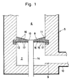
- Figures 1 to 3 show one preferred embodiment of this invention.
- Reference numeral 5 denotes a body of prereduction furnace
- 8 denotes a distributor partitioning the inside of furnace.
- the upper part of furnace above the distributor 8 constitutes a prereduction chamber 6, and the lower part below the distributor a gas blowing chamber 7.
- the blowing chamber 7 is equipped with a gas blowing inlet 9, to which is connected a gas supply pipe 10 that leads from the smelting reduction furnace.
- the distributor 8 has many vertical nozzles 15.
- the distributor 8 comprises a body 11 made of a refractory material, a metal plate 12 installed on the bottom of body 11, metallic pipes 16 inserted in the nozzles 15, and cooling pipes 17 installed along the bottom of the body 11 for flowing a cooling fluid .
- the metal plate 12 is fixedly secured to the body 11 of a refractory material so as to cover the entire bottom of the body 11. Holes are made in the metal plate 12 at the positions where the nozzles are formed.
- the metallic pipes 16 are inserted in the nozzles 15.
- the bottom end of metallic pipe 16 is joined to the peripheral of the hole made in the metal plate 12 by welding or other means.
- a plurality of cooling pipes 17 are arranged in parallel with each other along the bottom of the body 11.
- FIG. 3 is a plan view of metal plate 12 and cooling pipes 17 composing the distributor.
- the cooling pipes 17 arranged in parallel with each other are connected to headers 26 and 27 at each end.
- the headers 26 and 27 are connected to an intake pipe 28 and a discharge pipe for a cooling fluid, respectively.
- Reference numeral 30 denotes the nozzle hole made in metal plate 12.
- the cooling pipes 17 are preferably arranged at both sides of the nozzles 15 as shown in this preferred embodiment.
- In the center of the distributor is located an ore discharging hole 13, to which a discharge pipe 14 is connected.
- This invention can be applied to not only a distributor with an upper surface conically sloping down toward the center as shown in Fig.1 but also a distributor with a level upper surface.
- the sectional form and planar arrangement of cooling pipes are not limited to the above preferred embodiment, but the cooling pipes can be configured in an appropriate form.
- FIG 4 shows a distributor in which the cooling pipes are disposed in such a manner that they do not protrude from the bottom of metal plate.
- Most part of each cooling pipe 17 composing the distributor 8a is embedded in the body 11, and the bottom of cooling pipe 17 is flush with the bottom surface of metal plate 12.
- Other configurations are the same as those shown in Fig.1, and like reference numerals designate like or corresponding parts in these two figures.
- the arrangement of cooling pipes 17 is not limited to the embodiment shown in Fig.4.
- the bottom of cooling pipe 17 may be joined to the upper surface of metal plate 12, or it may be joined via connecting members.
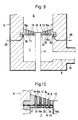
- Figure 5 shows a preferred embodiment in which the ore discharging hole 13 is located at the side of the distributor 8b.
- the distributor 8b is constructed so that its upper surface slopes downward toward the ore discharging hole 13.
- Other configurations are the same as those shown in Fig.4, and like reference numerals designate like or corresponding parts in these two figures.
- the cooling pipes 17 and the metal plate 12 can be constructed as shown in Fig.1; that is, the cooling pipes 17 can be disposed so that their upper halves are embedded in the body 11.
- FIGs 6 and 7 show a preferred embodiment in which purging pipes are installed below the distributor.
- the configuration of distributor is the same as that shown in Fig.1.
- two purging pipes 18 are installed in a horizontally movable manner so that the ore discharging pipe is interposed between them.
- the furnace body 5 has sleeves 20 passing through its side wall.
- the gas injection pipe 18 can be moved into and out of the blowing chamber 7 through the sleeve 20.
- driving mechanisms 21 are installed outside the furnace body.
- the driving mechanism 21 is, for example, made up of a reciprocating chain that is locked to a protrusion on the furnace outside.
- the reciprocating movement of chain allows the purging pipe 18 to move into and out of the blowing chamber 7 through the sleeve 20.
- a gas blowing pipe 22 To the rear end of purging pipe 18 extending from the furnace is connected a gas blowing pipe 22, to which a gas supply pipe 24 is connected from a gas source 23.
- a valve 25 is installed midway in the gas supply pipe 24.
- the purging pipe 18 may be so constructed as to be rotated around its axis by a driving mechanism not shown in the figure.
- These purging pipes can be installed in the furnace having the distributor shown in Fig.4 or 5.
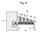
- cooling pipes 17 instead of the cooling pipes 17, other cooling pipes may be embedded in the body 11 at positions above the cooling pipes 17. As shown in Fig.8, the cooling pipes may be directly joined to the metallic pipes 16, or connected to the metallic pipes 16 or the metal plate 12 via connecting members.
- a cooling fluid is allowed to flow in the cooling pipes 17 composing the distributor 8, 8a, or 8b.
- the cooling fluid used for this furnace is water or nitrogen gas. A liquid like water is preferable.
- the cooling fluid cools down the metal plate 12 connected to the cooling pipes 17.
- the metallic pipes 16 inserted in the nozzles are cooled via the metal plate 12.
- the cooling down of metal plate 12 and in turn the metallic pipes 16 will reduce the temperature of the bottom of distributor and the inside of each nozzle. As a result, any dust in the reducing gas adhering to the bottom of distributor and the inside of nozzle will rapidly solidify, so that it can be easily removed.
- the top of distributor 8 is not cooled.
- the dust can be easily removed by injecting a gas from the purging pipes 18.
- the purging pipes 18 are normally withdrawn to the outside of furnace.
- gas is injected toward the bottom of distributor 8 through the gas injection outlets 19, the purging pipes are advanced into the blowing chamber 7 by means of the driving mechanisms 21.
- the conventional distributor made of only a refractory material has a thickness of about 700mm.
- the distributor according to this invention has the metal plate 12 and cooling pipes 17 as strength members.
- the distributor also has high strength because it is cooled. For these reasons, the thickness of distributor can be reduced to about 200mm. Therefore, the area where the reducing gas passing through the nozzle 15 comes into contact with the inside of nozzle is far smaller than with the conventional distributor of refractory material only, so that the decrease in temperature of reducing gas in passing through the nozzle hardly presents any problem.
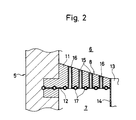
- Figures 9 to 12 show the preferred embodiment 2 of this invention.
- Reference numeral 5 denotes a body of prereduction furnace
- 8 denotes a distributor partitioning the inside of the furnace.
- the upper part of furnace above the distributor 8 constitutes a prereduction chamber 6, and the lower part below the distributor a gas blowing chamber 7.
- the blowing chamber 7 is equipped with a gas blowing inlet 9, to which is connected a gas supply pipe 10 that leads from the smelting reduction furnace.
- the distributor 8 has many vertical nozzles 15.
- the distributor 8 comprises a body 11 made of a refractory material, a metal plate 12 installed on the bottom of body 11, metallic pipes 16 inserted in the nozzles 15, cooling pipes 17 installed along the bottom of the body 11 for flowing a cooling fluid, and a metallic box 31 installed below the metal plate 12 that has passages for cooling the gas therein.
- the metal plate 12 is fixedly secured to the body 11 of a refractory material so as to cover the entire bottom of the body 11. Holes are made in the metal plate 12 at the positions where the nozzles are formed.
- the metallic pipes 16 are inserted in the nozzles 15a.
- the bottom end of metallic pipe 16 is joined to the peripheral of the hole made in the metal plate 12 by welding or other means.
- a plurality of cooling pipes 17 are arranged in parallel with each other along the bottom of the body 11.
- the cooling pipes 17 are joined to the metal plate 12 lengswise by welding or other means.
- the upper half of each cooling pipe 17 is embedded in the body 11. Therefore, the metal plate 12 is joined to the horizontal sides of cooling pipe 17.
- Figure 11 is a plan view of metal plate 12 and cooling pipes 17 composing the distributor.
- the cooling pipes 17 arranged in parallel with each other are connected to headers 26 and 27 at each end.
- the headers 26 and 27 are connected to an intake pipe 28 and a discharge pipe for a cooling fluid, respectively.
- Reference numeral 30 denotes the nozzle hole made in metal plate 12.
- the cooling pipes 17 are preferably arranged at both sides of the nozzles 15a as shown in this preferred embodiment.
- the metallic box 31 is made of a casting or other metals.
- the metallic box 31 is installed throughout below the metal plate 12 so that the bottom of metallic box defines the bottom of distributor.
- the metallic box 31 has passages 32 therein. Nozzles 15b leading to the metallic pipes 16 are disposed vertically in walls 33 partitioning the passages 32.
- the metallic box 31 has an intake port 34 and a discharge port 35 leading to the passages 32 to introduce and discharge a cooling gas. To the intake port 34 and the discharge port 35 are connected a gas supply pipe 38 and a discharge pipe 39, respectively.
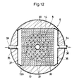
- FIG. 12 is a horizontal sectional view showing a typical inner construction of metallic box.
- the metallic box 31 has many passages arranged in parallel with each other therein.
- the passages 32 are connected to headers 36 and 37 at each end.
- the headers 36 and 37 have the intake port 34 and the discharge port 35 to introduce and discharge a cooling gas, respectively.
- To the intake port 34 is connected the gas supply pipe 38, and to the discharge port the discharge pipe 39.
- the nozzles 15b In the wall 33 partitioning the passages 32 are disposed the nozzles 15b.
- an ore discharging hole 13 In the center of the distributor 8 is located an ore discharging hole 13, to which an ore discharging pipe 14 is connected.
- This invention can be applied to not only a distributor with an upper surface conically sloping down toward the center as shown in Fig.9 but also a distributor with a level upper surface.
- the sectional form and planar arrangement of cooling pipes are not limited to the above preferred embodiment, but the cooling pipes can be configured in an appropriate form.
- Figure 13 shows a distributor in which the cooling pipes are disposed differently. Most part of each cooling pipe 17 composing the distributor 8a is embedded in the body 11, and the bottom of cooling pipe 17 is flush with the bottom surface of metal plate 12.
- Other configurations are the same as those shown in Fig.9, like reference numerals designating like or corresponding parts in these two figures for omitting the explanation.
- cooling pipes 17 may be joined to the upper surface of metal plate 12.
- the cooling pipes 17 may be completely embedded in the body 11 and connected to the metal plate 12 via connecting members.
- the cooling pipe 17 is preferably joined to the metal plate 12 throughout its length, but may be partially joined via connecting members.
- Figure 14 shows a preferred embodiment in which the ore discharging hole 13 is located at the side of the distributor 8b.
- the distributor 8b is constructed so that its upper surface slopes downward toward the ore discharging hole 13.
- Other configurations are the same as those shown in Fig.13, like reference numerals designating like or corresponding parts in these two figures for omitting the explanation.
- the cooling pipes 17 and the metal plate 12 can be constructed as shown in Fig.9; that is, the cooling pipes 17 can be disposed so that their upper halves are embedded in the body 11.
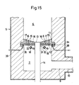
- FIGs 15 and 16 show a preferred embodiment in which purging pipes are installed below the distributor.
- the configuration of distributor is the same as that shown in Fig.9.
- two purging pipes 18 are installed in a horizontally movable manner so that the ore discharge pipe is interposed between them.
- Each of the purging pipes 18 has a plurality of gas injection outlets 19 facing the bottom of distributor.
- the furnace body 5 has sleeves 20 passing through its side wall.
- the purging pipe 18 can be moved into and out of the blowing chamber 7 through the sleeve 20.
- driving mechanisms 21 are installed outside the furnace body.
- the driving mechanism 21 is, for example, made up of a reciprocating chain that is locked to a protrusion on the furnace outside.
- the purging pipe 18 may be so constructed as to be rotated around its axis by a driving mechanism not shown in the figure. These purging pipes can be installed in the furnace having the distributor shown in Fig.13 or 14.
- cooling pipes 17 in addition to the cooling pipes 17, other cooling pipes may be embedded in the body 11 at positions above the cooling pipes 17.
- the cooling pipes may be directly joined to the metallic pipes 16, or may be connected to the metallic pipes 16 or the metal plate 12 via connecting members.
- a cooling fluid like water is allowed to flow in the cooling pipes 17 composing the distributor 8, 8a, or 8b.
- the cooling fluid cools down the metal plate 12 connected to the cooling pipes 17.
- the metallic pipes 16 inserted in the nozzles are cooled via the metal plate 12.
- Any adherent dust in the reducing gas adhering to the inside of metallic pipe 16 rapidly solidify, so that it can be easily removed.
- a cooling gas like nitrogen gas is allowed to flow. This cooling gas slowly cools down the bottom surface of metallic box 31 constituting the bottom of distributor. Any dust adhering to the bottom of distributor can be easily peeled off even by such slow cooling because of its small adhesive force.
- the slow cooling of distributor bottom prevents the decrease in temperature of reducing gas in contact with the bottom of distributor.
- the top of distributor 8 is not cooled. This is because any dust adhering to the top of distributor 8 and the outlet of nozzle 15 is readily removed by the violent movement of fluidized ore particles. Here is, therefore, almost no adhesion of dust commonly found on the bottom of distributor and the inside of nozzle. No cooling of distributor top prevents the decrease in temperature in the fluidized bed due tothe heat dissipation from the distributor top.
- the dust can be easily removed by injecting gas from the purging pipes 18.
- the purging pipes 18 are normally withdrawn to the outside of furnace and are advanced into the blowing chamber 7 by means of the driving mechanism 21 as appropriate.
- the conventional distributor made of only a refractory material has a thickness of about 700mm.
- the distributor according to this invention has the metal plate 12, cooling pipes 17, and metallic box 31 as strength members.
- the distributor also has high strength because the metal plate 12, cooling pipes 17, and metallic box 31 are cooled. For these reasons, the thickness of distributor can be reduced to about 200mm. Therefore, the area where the reducing gas passing through the nozzle 15 comes into contact with the inside of nozzle is far smaller than with the conventional distributor of refractory material only, so that the decrease in temperature of reducing gas in passing through the nozzle hardly presents any problem.
- the installation of metallic box 31 reduces a difference in temperature between the area near the joint with the cooling pipe 17 and the area near the joint with the metallic pipe 16 on the metal plate 12, which prevents heat cracking of metal plate 12.
- the cooling gas in the metallic box 31 prevents the area of metal plate near the cooling pipe 17 from being excessively cooled by the heavy cooling due to the cooling pipe 17. This reduces a difference in temperature between the area near the cooling pipe 17 and the area near the joint with the metallic pipe 16 on the metal plate 12, preventing heat cracking of metal plate 12 due to an excessive difference in temperature.
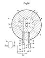
- FIG. 17 to 19 show the preferred embodiment 3 of this invention.
- Reference numeral 105 denotes a body of prereduction furnace, and 108 denotes a distributor partitioning the inside of the furnace.
- the upper part of furnace above the distributor 108 constitutes a prereduction chamber 106, and the lower part below the distributor a blowing chamber 107.
- the blowing chamber 107 is equipped with a gas blowing inlet 109, to which is connected a gas supply pipe 110 that leads from the smelting reduction furnace.
- the distributor 108 has many vertical nozzles 115a.
- the distributor 108 comprises a body 111 made of a refractory material, a metal plate 112 installed on the bottom of body 111, metallic pipes 116 inserted in the nozzles 115a, cooling pipes 117 installed along the bottom of the body 111 for flowing a cooling fluid , a bottom plate 131 spaced suitably from the metal plate 112 thereunder, and metallic pipes 132 installed at the lower ends of metallic pipes 116 for defining nozzles 115b between the metal plate 112 and the bottom plate 131.
- the nozzle 115b leads to the nozzle 115a.
- the metal plate 112 is fixedly secured to the body 111 of a refractory material so as to cover the entire bottom of the body 111. Holes are made in the metal plate 112 at the positions where the nozzles are formed.
- the metallic pipes 116 are inserted in the nozzles 115a.
- the bottom end of metallic pipe 116 is joined to the peripheral of the hole made in the metal plate 112 by welding or other means.
- a plurality of cooling pipes 117 are arranged in parallel with each other along the bottom of the body 111.
- the cooling pipes 117 are joined to the metal plate 112 lengswise by welding or other means. In this preferred embodiment, the upper half of each cooling pipe 117 is embedded in the body 111. Therefore, the metal plate 112 is joined to the horizontal sides of cooling pipe 117.
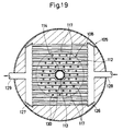
- Figure 19 is a plan view of metal plate 112 and cooling pipes 117 composing the distributor.
- the cooling pipes 117 arranged in parallel with each other are connected to headers 126 and 127 at each end.
- the headers 126 and 127 are connected to an intake pipe 128 and a discharge pipe for a cooling fluid, respectively.
- Reference numeral 130 denotes the nozzle hole made in metal plate 112.
- the cooling pipes 117 are preferably arranged at both sides of the nozzles 115a as shown in this preferred embodiment.
- the bottom plate 131 constitutes the bottom of distributor.
- the bottom plate 131 is spaced suitably from the metal plate 112 thereunder.
- a chamber 134 is formed between the metal plate 112 and the bottom plate 131.
- a plate-shaped or rod-shaped connecting member 133 is installed between the cooling pipe 117 and the bottom plate 131.
- the metallic pipe 132 is installed at the lower end of metallic pipe 116.
- the lower end of metallic pipe 132 is open at the lower surface of bottom plate 131.
- the nozzle 115b following the nozzle 115a is formed between the metal plate 112 and the bottom plate 131.
- the metallic pipe 132 is composed of a metallic pipe integral with the metallic pipe 116.
- a connecting member 133 as described above is installed as necessary between the bottom plate 131 and the metal plate 112 or between the bottom plate 131 and the cooling pipe 117 for heat transfer.
- connecting members 133 may be installed between the metal plate 112 and the bottom plate 131, for example, as shown in Fig.20.
- the connecting members can be installed in any form as necessary. In some cases, the distributor may be constructed without the connecting members.
- This invention can be applied to not only a distributor with an upper surface conically sloping down toward the center as shown in Fig.17 but also a distributor with a level upper surface.
- the sectional form and planar arrangement of cooling pipes 117 are not limited to the above preferred embodiment, but the cooling pipes can be configured in an appropriate form.
- Figure 21 shows a distributor in which the cooling pipes are disposed differently. Most part of each cooling pipe 117 composing the distributor 108a is embedded in the body 111, and the bottom of cooling pipe 117 is flush with the bottom surface of metal plate 112.
- Other configurations are the same as those shown in Fig.17, like reference numerals designating like or corresponding parts in these two figures for omitting the explanation.
- cooling pipes 117 may be joined to the upper surface of metal plate 112.
- the cooling pipes 117 may be completely embedded in the body 111 and connected to the metal plate 112 via connecting members.
- the cooling pipe 117 is preferably joined to the metal plate 12 throughout its length, but may be partially joined via connecting members.
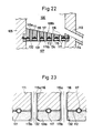
- Figure 22 shows a preferred embodiment in which the ore discharging hole 113 is located at the side of the distributor 108b.
- the distributor 108b is constructed so that its upper surface slopes downward toward the ore discharging hole 113.
- Other configurations are the same as those shown in Fig.21, like reference numerals designating like or corresponding parts in these two figures for omitting the explanation.
- the cooling pipes 117 and the metal plate 112 can be constructed as shown in Fig.17; that is, the cooling pipes 117 can be disposed so that their upper halves are embedded in the body 111.
- Figure 23 shows the preferred embodiment in which the bottom plate is brought into direct contact with the metal plate 112.
- the bottom plate 131a is made of a thick metal plate like a casting.
- the metallic pipe 132 is disposed at the lower end of the metallic pipe 116 and passes through the bottom plate 131a.
- the nozzle 115b follows the nozzle 115a.
- the material of the bottom plate 131a is preferably a metal because of better heat transfer.
- the bottom plate 131a may be sometimes of refractory material.
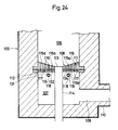
- Figures 24 and 25 show a preferred embodiment in which purging pipes are installed below the distributor.
- the configuration of distributor is the same as that shown in Fig.17. Below the distributor, two purging pipes 118 are installed in a horizontally movable manner so that the ore discharge pipe is interposed between them.
- Each of the purging pipes 118 has a plurality of gas injection outlets 119 facing the bottom of distributor.
- the furnace body 105 has sleeves 120 passing through its side wall.
- the purging pipe 118 can be moved into and out of the blowing chamber 107 through the sleeve 120.
- driving mechanisms 121 are installed outside the furnace body.
- the driving mechanism 121 is, for example, made up of a reciprocating chain that is locked to a protrusion on the furnace outside. Therefore, the reciprocating movement of chain allows the purging pipe 118 to move into and out of the blowing chamber 107 through the sleeve 120.
- To the rear end of purging pipe 118 extending from the furnace is connected a gas blowing pipe 122, to which a gas supply pipe 124 is connected from a gas source 123.
- a valve 125 is installed midway in the gas supply pipe 124.
- the purging pipe 118 may be so constructed as to be rotated around its axis by a driving mechanism not shown in the figure. These purging pipes can be installed in the furnace having the distributor shown in Fig.21 or 22.
- cooling pipes 117 in addition to the cooling pipes 117, other cooling pipes may be embedded in the body 111 at positions above the cooling pipes 117.
- the cooling pipes may be directly joined to the metallic pipes 116, or may be connected to the metallic pipes 116 or the metal plate 112 via connecting members 134.
- Figures 26 and 27 show other embodiments.
- the cooling pipes 135 are embedded in the body 111 above the cooling pipes117.
- the cooling pipe 135 is connected to the metallicpipe 116 by the connecting member 134 of a metal plate or the like.
- a cooling fluid like water is allowed to flow in the cooling pipes 117 composing the distributor 108, 108a, or 108b.
- the cooling fluid cools down the metal plate 112 connected to the cooling pipes 117.
- the metallic pipes 116 and 132 inserted in the nozzles are cooled via the metal plate 112. Any adherent dust in the reducing gas adhering to the inside of metallic pipe 116 will rapidly solidify, so that it can be easily removed.
- the lower surface of bottom plate 131 constituting the distributor bottom is slowly cooled by the cooling fluid in the cooling pipes 117 via the chamber 134 formed between the metal plate 112 and the bottomplate 131, the metallic pipes 132 installed between the metal pipe 112 and the bottom plate 131, and the connecting members 133.
- the lower surface of the bottom plate 131 constituting the distributor bottom is slowly cooled by the cooling fluid in the cooling pipes 117 via the bottom plate 131a. Any dust adhering to the bottom of distributor can be easily peeled off even by such slow cooling because of its small adhesive force.
- the slow cooling of distributor bottom prevents the decrease in temperature of reducing gas in contact with the bottom of distributor.
- the top of distributor 108 is not cooled. This is because any dust adhering to the top of distributor 108 and the outlet of nozzle 115 is readily removed by the violent movement of fluidized ore particles. Here is, therefore, almost no adhesion of dust commonly found on the bottom of distributor and the inside of nozzle. No cooling of distributor top prevents the decrease in temperature in the fluidized bed due to the heat dissipation from the distributor top.
- the dust can be easily removed by injecting gas from the purging pipes 118.
- the purging pipes 118 are normally withdrawn to the outside of furnace and are advanced into the blowing chamber 107 by means of the driving mechanism 121 as appropriate.
- the conventional distributor made of only a refractory material has a thickness of about 700mm.
- the distributor according to this invention has the metal plate 112 , cooling pipes 117, and bottom plates 131 and 131a as strength members.
- the distributor also has high strength because the metal plate 112, cooling pipes 117, and bottom plates 131 and 131a are cooled.
- the thickness of distributor can be reduced to about 200mm. Therefore, the area where the reducing gas passing through the nozzle 115 comes into contact with the inside of nozzle is far smaller than with the conventional distributor of refractory material only, so that the decrease in temperature of reducing gas in passing through the nozzle hardly presents any problem.
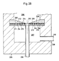
- Figures 28 and 29 show the preferred embodiment 4 of this invention.
- Reference numeral 205 denotes a body of prereduction furnace, and 208 denotes a distributor partitioning the inside of the furnace.
- the upper part of furnace above the distributor 208 constitutes a prereduction chamber 206, and the lower part below the distributor a blowing chamber 207.
- the blowing chamber 207 is equipped with a gas blowing inlet 209, to which is connected a gas supply pipe 210 that leads from the smelting reduction furnace.
- the distributor 208 comprises a thick plate 211 of high rigidity with passages 214 for a cooling fluid formed therein and a refractory layer 212 placed above the thick plate 211.
- the thick plate is made of a casting or other metallic or ceramic materials of high rigidity.
- the passage 214 has a groove on the top of thick plate 211, and the upper end of groove is closed by a plate.
- the distributor 208 has many vertical nozzles. Each nozzle is composed of the nozzle 213 in the thick plate 211 and the nozzle 330 in the refractory layer 212. The nozzle 213 connects to the nozzle 330. The nozzle 330 has a diameter increasing upward. The inside angle ⁇ of nozzle 330 expanding upward is designed so that fluidized ore particles enter the inside of nozzle. Generally, the angle ⁇ is preferably about 10 to 45 degrees.
- the thick plate 211 has an intake port and a discharge port for a cooling fluid (not shown) which lead to the passages 214. In the center of the distributor 208 is located an ore discharging hole 215, to which an ore discharge pipe 216 is connected.
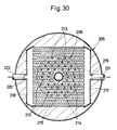
- the thick plate 211 composing the distributor 208 is usually made of a casting or the like, and the inner construction of thick plate 211 is not particularly limited.
- Figure 30 shows the inner construction of thick plate 211.
- many passages 214 are arranged in parallel with each other.
- Each end of passage 214 is connected to headers 217 and 218.
- the headers 217 and 218 have an intake port 219 and a discharge port 220 for a cooling fluid, respectively.
- To the intake port 219 and the discharge port 220 are connected a supply pipe 221 and a discharge pipe 222 for a cooling fluid, respectively.
- the nozzles 213 are arranged between the passages 214.
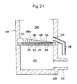
- FIG. 31 shows a preferred embodiment in which the ore discharging hole 215 is located at the side of the distributor 208a.
- the distributor 208a is constructed so that its upper surface slopes downward toward the ore discharging hole 215.
- Other configurations are the same as those shown in Fig.28, like reference numerals designating like or corresponding parts in these two figures for omitting the explanation.
- Figures 32 and 33 show a preferred embodiment in which purging pipes are installed below the distributor.
- the configuration of distributor is the same as that shown in Fig.28.
- the furnace body 205 has sleeves 225 passing through its side wall.
- the purging pipe 223 can be moved into and out of the blowing chamber 207 through the sleeve 225.
- driving mechanisms 226 are installed outside the furnace body.
- the driving mechanism 226 is, for example, made up of a reciprocating chain that is locked to a protrusion on the furnace outside.
- the purging pipe 223 may be so constructed as to be rotated around its axis by a driving mechanism not shown in the figure. These purging pipes can be installed in the furnace having the distributor shown in Fig.31.
- the thick plate 211 of distributor has an advantage of being easier to manufacture than the distributor consisting of a combination of pipes and plates because it is made of single plate. Since the distributor is subject to very high temperatures, the distributor consisting of a combination of pipes and plates has difficulties in designing their joints and in manufacturing.
- a cooling fluid like water introduced into the thick plate 211 of distributor 208 or 208a flows through a plurality of passages 214 and then is discharged through the discharge port.
- the cooling fluid decreases the temperature of the bottom of distributor and the inside of nozzle 213. Any adherent dust in the reducing gas adhering to the bottom of distributor and the inside of nozzle 213 will rapidly solidify, so that it can be easily removed.
- the refractory layer 212 composing the upper part of distributor 208 or 208a prevents the decrease in temperature in the fluidized bed due to the heat dissipation from the distributor top. In addition, it properly prevents the wear of distributor top due to the contact with fluidized ore particles.
- the cooling action of cooling fluid hardly reach the inside of nozzle 330 in the refractory layer 212. However, the upward increase in inside diameter of nozzle 330 allows ore particles to enter the nozzle 330 and to flow in it, so that the adhesion of dust is prevented by the flow of ore particles.
- the dust can be easily removed by injecting gas from the purging pipes 223.
- the purging pipes 223 are normally withdrawn to the outside of furnace and are advanced into the blowing chamber 207 by means of the driving mechanism 226 as appropriate.
- the conventional distributor made of only a refractory material has a thickness of about 700mm.
- the distributor according to this invention has high strength because its thick plate 211 is made of a metal or other rigid materials and is cooled. For this reason, the thickness of distributor can be reduced to about 200mm. Therefore, the area where the reducing gas passing through the nozzle 213 comes into contact with the inside of nozzle is far smaller than with the conventional distributor of refractory material only, so that the decrease in temperature of reducing gas in passing through the nozzle hardly presents any problem.
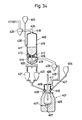
- FIG 34 is a schematic view of a smelting reduction facility according to this invention.
- the smelting reduction facility comprises a smelting reduction furnace 401 of a converter type, a prereduction furnace 402 for prereducing iron ore of a main raw material supplied to the smelting reduction furnace 401, a reservoir 403 of main raw material, and a reservoir 404 of auxiliary materials.
- the smelting reduction furnace 401 comprises a furnace body 405 of a converter type, a lance 406 vertically inserted into the furnace body 405 through the throat of furnace body 405, a stirring gas blowing inlets 407 installed in the bottom and side walls of furnace body 405, a chute 409 installed in a hood 408 covering the throat for supplying main raw material, a chute 410 for supplying auxiliary materials, and a gas discharge outlet 411.
- the prereduction furnace 402 comprises a distributor 412 having many nozzles 413 installed at the lower position of the furnace, a blowing chamber 414 formed below the distributor 412, and a prereduction chamber 415 formed above the distributor 412 in the furnace.
- the blowing chamber 414 has a gas blowing inlet 416
- the prereduction chamber 415 has a chute 417 for supplying raw material and a gas discharge outlet 418.
- An ore discharging hole is installed in the center of the distributor, and to the ore discharging hole is connected an ore discharging pipe 419 for discharging the iron ore that has been prereduced.
- the ore discharging pipe 419 passing through the bottom wall of prereduction furnace 402, extends downward and is connected to the chute 409 of smelting reduction furnace 401 through an L-shaped valve 420 and two intermediate reservoirs 421.
- a dust collecting cyclone 423 is installed midway in the gas supply pipe 422.
- a gas discharge pipe 424 is connected to the gas discharge outlet 418 of the prereduction furnace 402, and a dust collecting cyclone 425 is installed midway in the gas discharge pipe 424.
- the reservoir 403 of main raw material is connected to the chute 417 for supplying raw material to the prereduction furnace 402 by a duct 426, while the reservoir 404 of auxiliary materials is connected to the chute 410 for supplying auxiliary materials to the smelting reduction furnace 401.
Landscapes
- Chemical & Material Sciences (AREA)
- Engineering & Computer Science (AREA)
- Organic Chemistry (AREA)
- Combustion & Propulsion (AREA)
- Metallurgy (AREA)
- Materials Engineering (AREA)
- Manufacturing & Machinery (AREA)
- Chemical Kinetics & Catalysis (AREA)
- Dispersion Chemistry (AREA)
- Manufacture Of Iron (AREA)
- Vertical, Hearth, Or Arc Furnaces (AREA)
- Furnace Charging Or Discharging (AREA)
- Crucibles And Fluidized-Bed Furnaces (AREA)
- Furnace Details (AREA)
- Manufacture And Refinement Of Metals (AREA)
Applications Claiming Priority (8)
| Application Number | Priority Date | Filing Date | Title |
|---|---|---|---|
| JP158157/90 | 1990-06-16 | ||
| JP158156/90 | 1990-06-16 | ||
| JP15815790A JPH07103413B2 (ja) | 1990-06-16 | 1990-06-16 | 鉄鉱石の溶融還元設備における予備還元炉 |
| JP15815890A JPH07103414B2 (ja) | 1990-06-16 | 1990-06-16 | 鉄鉱石の溶融還元設備における予備還元炉 |
| JP15815690A JPH07103412B2 (ja) | 1990-06-16 | 1990-06-16 | 鉄鉱石の溶融還元設備における予備還元炉 |
| JP158158/90 | 1990-06-16 | ||
| JP169190/90 | 1990-06-27 | ||
| JP2169190A JPH0826381B2 (ja) | 1990-06-27 | 1990-06-27 | 鉄鉱石の溶融還元設備における予備還元炉 |
Publications (3)
| Publication Number | Publication Date |
|---|---|
| EP0462515A2 true EP0462515A2 (de) | 1991-12-27 |
| EP0462515A3 EP0462515A3 (en) | 1992-03-11 |
| EP0462515B1 EP0462515B1 (de) | 1995-12-20 |
Family
ID=27473526
Family Applications (1)
| Application Number | Title | Priority Date | Filing Date |
|---|---|---|---|
| EP91109752A Expired - Lifetime EP0462515B1 (de) | 1990-06-16 | 1991-06-14 | Ofen zum Vorreduzieren von Eisenerzen für eine Schmelzreduktionsanlage |
Country Status (9)
| Country | Link |
|---|---|
| US (1) | US5129630A (de) |
| EP (1) | EP0462515B1 (de) |
| KR (1) | KR930005064B1 (de) |
| AT (1) | ATE131880T1 (de) |
| AU (1) | AU632944B2 (de) |
| BR (1) | BR9102462A (de) |
| CA (1) | CA2044638C (de) |
| DE (1) | DE69115572T2 (de) |
| ES (1) | ES2084060T3 (de) |
Cited By (3)
| Publication number | Priority date | Publication date | Assignee | Title |
|---|---|---|---|---|
| WO2000012206A1 (de) * | 1998-08-26 | 2000-03-09 | Voest-Alpine Industrieanlagenbau Gmbh | Reaktorgefäss zum behandeln eines fluidisierbaren materials |
| WO2013011082A1 (de) * | 2011-07-19 | 2013-01-24 | H S Reformer Gmbh | Düsenboden mit wärmerohren |
| WO2014009504A3 (en) * | 2012-07-12 | 2014-04-17 | Siliken Chemicals, Sl | Cooled gas distribution plate, thermal bridge breaking system, and related methods |
Families Citing this family (3)
| Publication number | Priority date | Publication date | Assignee | Title |
|---|---|---|---|---|
| AT400447B (de) * | 1994-03-04 | 1995-12-27 | Voest Alpine Ind Anlagen | Verfahren und anlage zum chargieren von erz |
| US6224649B1 (en) | 1998-07-06 | 2001-05-01 | Hylsa, S.A. De C.V. | Method and apparatus for reducing iron-oxides-particles having a broad range of sizes |
| CN101845529B (zh) * | 2010-06-02 | 2011-12-07 | 首钢总公司 | 一种熔融还原炼铁用预热还原炉 |
Family Cites Families (8)
| Publication number | Priority date | Publication date | Assignee | Title |
|---|---|---|---|---|
| US3016624A (en) * | 1959-01-02 | 1962-01-16 | Foster Wheeler Corp | Gas distribution baffle |
| US3553847A (en) * | 1968-09-09 | 1971-01-12 | Fuller Co | Fluidized bed reactor |
| SE438729B (sv) * | 1980-03-21 | 1985-04-29 | Asea Ab | Anordning vid botten av en fluidiserbar bedd |
| GB2073041B (en) * | 1980-04-03 | 1983-11-23 | Coal Industry Patents Ltd | Fluidised bed distributor plates |
| DE3025924A1 (de) * | 1980-07-09 | 1982-02-04 | Dieter 5060 Bergisch Gladbach Popp | Fluessigkeitsgekuehlter stuetzboden fuer eine wirbelschichttrockner |
| AU596758B2 (en) * | 1987-11-13 | 1990-05-10 | Jp Steel Plantech Co. | Metal-making apparatus involving the smelting reduction of metallic oxides |
| AU636199B2 (en) * | 1990-02-27 | 1993-04-22 | Jfe Steel Corporation | Prereduction furnace of a smelting reduction facility of iron ore |
| JP2536217B2 (ja) * | 1990-02-27 | 1996-09-18 | 日本鋼管株式会社 | 溶融還元設備における予備還元炉の分散盤下面に付着したダストの除去装置 |
-
1991
- 1991-06-05 US US07/710,678 patent/US5129630A/en not_active Expired - Fee Related
- 1991-06-12 AU AU78406/91A patent/AU632944B2/en not_active Ceased
- 1991-06-13 KR KR1019910009756A patent/KR930005064B1/ko not_active Expired - Fee Related
- 1991-06-14 ES ES91109752T patent/ES2084060T3/es not_active Expired - Lifetime
- 1991-06-14 CA CA002044638A patent/CA2044638C/en not_active Expired - Fee Related
- 1991-06-14 AT AT91109752T patent/ATE131880T1/de not_active IP Right Cessation
- 1991-06-14 EP EP91109752A patent/EP0462515B1/de not_active Expired - Lifetime
- 1991-06-14 BR BR919102462A patent/BR9102462A/pt not_active IP Right Cessation
- 1991-06-14 DE DE69115572T patent/DE69115572T2/de not_active Expired - Fee Related
Cited By (4)
| Publication number | Priority date | Publication date | Assignee | Title |
|---|---|---|---|---|
| WO2000012206A1 (de) * | 1998-08-26 | 2000-03-09 | Voest-Alpine Industrieanlagenbau Gmbh | Reaktorgefäss zum behandeln eines fluidisierbaren materials |
| WO2013011082A1 (de) * | 2011-07-19 | 2013-01-24 | H S Reformer Gmbh | Düsenboden mit wärmerohren |
| WO2014009504A3 (en) * | 2012-07-12 | 2014-04-17 | Siliken Chemicals, Sl | Cooled gas distribution plate, thermal bridge breaking system, and related methods |
| US8875728B2 (en) | 2012-07-12 | 2014-11-04 | Siliken Chemicals, S.L. | Cooled gas distribution plate, thermal bridge breaking system, and related methods |
Also Published As
| Publication number | Publication date |
|---|---|
| US5129630A (en) | 1992-07-14 |
| KR930005064B1 (ko) | 1993-06-15 |
| ES2084060T3 (es) | 1996-05-01 |
| AU7840691A (en) | 1991-12-19 |
| CA2044638A1 (en) | 1991-12-17 |
| DE69115572T2 (de) | 1996-06-13 |
| EP0462515A3 (en) | 1992-03-11 |
| KR920000947A (ko) | 1992-01-29 |
| ATE131880T1 (de) | 1996-01-15 |
| AU632944B2 (en) | 1993-01-14 |
| BR9102462A (pt) | 1992-01-21 |
| DE69115572D1 (de) | 1996-02-01 |
| EP0462515B1 (de) | 1995-12-20 |
| CA2044638C (en) | 2001-02-13 |
Similar Documents
| Publication | Publication Date | Title |
|---|---|---|
| US5129630A (en) | Prereduction furnace of a smelting reduction facility of iron ore | |
| US5149062A (en) | Prereduction furnace of a smelting reduction facility of iron ore | |
| CA2036972C (en) | Prereduction furnace of a smelting reduction facility of iron ore | |
| JP2536216B2 (ja) | 溶融還元設備における予備還元炉の分散盤 | |
| JPH0448015A (ja) | 鉄鉱石の溶融還元設備における予備還元炉 | |
| JPH04297515A (ja) | 鉄鉱石の溶融還元設備における予備還元炉 | |
| JP2762970B2 (ja) | 鉄鉱石の溶融還元設備における予備還元炉 | |
| JPH0448016A (ja) | 鉄鉱石の溶融還元設備における予備還元炉 | |
| JPH07103412B2 (ja) | 鉄鉱石の溶融還元設備における予備還元炉 | |
| JPH0448014A (ja) | 鉄鉱石の溶融還元設備における予備還元炉 | |
| JPH0459906A (ja) | 鉄鉱石の溶融還元設備における予備還元炉 | |
| JPH0463216A (ja) | 溶融還元装置 | |
| JPH07103409B2 (ja) | 溶融還元設備における予備還元炉の鉄鉱石排出管閉塞防止方法 | |
| JPH03173710A (ja) | 鉱石の流動層式還元炉およびこれを使用した溶融還元法 | |
| JPH07103411B2 (ja) | 鉄鉱石の溶融還元設備における予備還元炉 | |
| JPH04314812A (ja) | 鉱石の還元炉および還元装置 |
Legal Events
| Date | Code | Title | Description |
|---|---|---|---|
| PUAI | Public reference made under article 153(3) epc to a published international application that has entered the european phase |
Free format text: ORIGINAL CODE: 0009012 |
|
| 17P | Request for examination filed |
Effective date: 19910614 |
|
| AK | Designated contracting states |
Kind code of ref document: A2 Designated state(s): AT BE DE ES FR GB IT NL SE |
|
| PUAL | Search report despatched |
Free format text: ORIGINAL CODE: 0009013 |
|
| AK | Designated contracting states |
Kind code of ref document: A3 Designated state(s): AT BE DE ES FR GB IT NL SE |
|
| 17Q | First examination report despatched |
Effective date: 19940412 |
|
| GRAA | (expected) grant |
Free format text: ORIGINAL CODE: 0009210 |
|
| AK | Designated contracting states |
Kind code of ref document: B1 Designated state(s): AT BE DE ES FR GB IT NL SE |
|
| REF | Corresponds to: |
Ref document number: 131880 Country of ref document: AT Date of ref document: 19960115 Kind code of ref document: T |
|
| ITF | It: translation for a ep patent filed | ||
| REF | Corresponds to: |
Ref document number: 69115572 Country of ref document: DE Date of ref document: 19960201 |
|
| ET | Fr: translation filed | ||
| REG | Reference to a national code |
Ref country code: ES Ref legal event code: FG2A Ref document number: 2084060 Country of ref document: ES Kind code of ref document: T3 |
|
| PLBE | No opposition filed within time limit |
Free format text: ORIGINAL CODE: 0009261 |
|
| STAA | Information on the status of an ep patent application or granted ep patent |
Free format text: STATUS: NO OPPOSITION FILED WITHIN TIME LIMIT |
|
| 26N | No opposition filed | ||
| PGFP | Annual fee paid to national office [announced via postgrant information from national office to epo] |
Ref country code: SE Payment date: 19990414 Year of fee payment: 9 |
|
| PGFP | Annual fee paid to national office [announced via postgrant information from national office to epo] |
Ref country code: FR Payment date: 19990610 Year of fee payment: 9 |
|
| PG25 | Lapsed in a contracting state [announced via postgrant information from national office to epo] |
Ref country code: SE Free format text: LAPSE BECAUSE OF NON-PAYMENT OF DUE FEES Effective date: 20000615 |
|
| EUG | Se: european patent has lapsed |
Ref document number: 91109752.5 |
|
| PG25 | Lapsed in a contracting state [announced via postgrant information from national office to epo] |
Ref country code: FR Free format text: LAPSE BECAUSE OF NON-PAYMENT OF DUE FEES Effective date: 20010228 |
|
| REG | Reference to a national code |
Ref country code: FR Ref legal event code: ST |
|
| REG | Reference to a national code |
Ref country code: GB Ref legal event code: IF02 |
|
| PGFP | Annual fee paid to national office [announced via postgrant information from national office to epo] |
Ref country code: GB Payment date: 20030611 Year of fee payment: 13 Ref country code: AT Payment date: 20030611 Year of fee payment: 13 |
|
| PGFP | Annual fee paid to national office [announced via postgrant information from national office to epo] |
Ref country code: ES Payment date: 20030619 Year of fee payment: 13 |
|
| PGFP | Annual fee paid to national office [announced via postgrant information from national office to epo] |
Ref country code: DE Payment date: 20030626 Year of fee payment: 13 |
|
| PGFP | Annual fee paid to national office [announced via postgrant information from national office to epo] |
Ref country code: NL Payment date: 20030630 Year of fee payment: 13 |
|
| PGFP | Annual fee paid to national office [announced via postgrant information from national office to epo] |
Ref country code: BE Payment date: 20030820 Year of fee payment: 13 |
|
| PG25 | Lapsed in a contracting state [announced via postgrant information from national office to epo] |
Ref country code: GB Free format text: LAPSE BECAUSE OF NON-PAYMENT OF DUE FEES Effective date: 20040614 Ref country code: AT Free format text: LAPSE BECAUSE OF NON-PAYMENT OF DUE FEES Effective date: 20040614 |
|
| PG25 | Lapsed in a contracting state [announced via postgrant information from national office to epo] |
Ref country code: ES Free format text: LAPSE BECAUSE OF NON-PAYMENT OF DUE FEES Effective date: 20040615 |
|
| PG25 | Lapsed in a contracting state [announced via postgrant information from national office to epo] |
Ref country code: BE Free format text: LAPSE BECAUSE OF NON-PAYMENT OF DUE FEES Effective date: 20040630 |
|
| BERE | Be: lapsed |
Owner name: *NKK CORP. Effective date: 20040630 |
|
| PG25 | Lapsed in a contracting state [announced via postgrant information from national office to epo] |
Ref country code: NL Free format text: LAPSE BECAUSE OF NON-PAYMENT OF DUE FEES Effective date: 20050101 Ref country code: DE Free format text: LAPSE BECAUSE OF NON-PAYMENT OF DUE FEES Effective date: 20050101 |
|
| GBPC | Gb: european patent ceased through non-payment of renewal fee |
Effective date: 20040614 |
|
| NLV4 | Nl: lapsed or anulled due to non-payment of the annual fee |
Effective date: 20050101 |
|
| PG25 | Lapsed in a contracting state [announced via postgrant information from national office to epo] |
Ref country code: IT Free format text: LAPSE BECAUSE OF NON-PAYMENT OF DUE FEES;WARNING: LAPSES OF ITALIAN PATENTS WITH EFFECTIVE DATE BEFORE 2007 MAY HAVE OCCURRED AT ANY TIME BEFORE 2007. THE CORRECT EFFECTIVE DATE MAY BE DIFFERENT FROM THE ONE RECORDED. Effective date: 20050614 |
|
| REG | Reference to a national code |
Ref country code: ES Ref legal event code: FD2A Effective date: 20040615 |