EP0462500B2 - Housing for a rotary valve - Google Patents
Housing for a rotary valve Download PDFInfo
- Publication number
- EP0462500B2 EP0462500B2 EP91109642A EP91109642A EP0462500B2 EP 0462500 B2 EP0462500 B2 EP 0462500B2 EP 91109642 A EP91109642 A EP 91109642A EP 91109642 A EP91109642 A EP 91109642A EP 0462500 B2 EP0462500 B2 EP 0462500B2
- Authority
- EP
- European Patent Office
- Prior art keywords
- housing
- bush
- wear
- elastomer
- flange
- Prior art date
- Legal status (The legal status is an assumption and is not a legal conclusion. Google has not performed a legal analysis and makes no representation as to the accuracy of the status listed.)
- Expired - Lifetime
Links
- 239000000463 material Substances 0.000 claims abstract description 9
- 229920001971 elastomer Polymers 0.000 claims description 34
- 239000000806 elastomer Substances 0.000 claims description 34
- 238000007667 floating Methods 0.000 claims description 17
- 229910052751 metal Inorganic materials 0.000 claims description 14
- 239000002184 metal Substances 0.000 claims description 14
- 229920003023 plastic Polymers 0.000 claims description 11
- 239000004033 plastic Substances 0.000 claims description 11
- 229910000639 Spring steel Inorganic materials 0.000 claims description 2
- 230000002787 reinforcement Effects 0.000 claims description 2
- 238000007373 indentation Methods 0.000 claims 1
- 238000007493 shaping process Methods 0.000 claims 1
- 239000013536 elastomeric material Substances 0.000 abstract 1
- 230000001413 cellular effect Effects 0.000 description 26
- 239000013590 bulk material Substances 0.000 description 4
- 230000000694 effects Effects 0.000 description 3
- 238000004519 manufacturing process Methods 0.000 description 3
- 238000007789 sealing Methods 0.000 description 3
- 238000005299 abrasion Methods 0.000 description 2
- 238000009434 installation Methods 0.000 description 2
- 239000002245 particle Substances 0.000 description 2
- 229910000906 Bronze Inorganic materials 0.000 description 1
- 229910001060 Gray iron Inorganic materials 0.000 description 1
- 229910000831 Steel Inorganic materials 0.000 description 1
- 229910052782 aluminium Inorganic materials 0.000 description 1
- XAGFODPZIPBFFR-UHFFFAOYSA-N aluminium Chemical compound [Al] XAGFODPZIPBFFR-UHFFFAOYSA-N 0.000 description 1
- 230000015572 biosynthetic process Effects 0.000 description 1
- 239000010974 bronze Substances 0.000 description 1
- 239000000919 ceramic Substances 0.000 description 1
- VNNRSPGTAMTISX-UHFFFAOYSA-N chromium nickel Chemical compound [Cr].[Ni] VNNRSPGTAMTISX-UHFFFAOYSA-N 0.000 description 1
- 238000001816 cooling Methods 0.000 description 1
- KUNSUQLRTQLHQQ-UHFFFAOYSA-N copper tin Chemical compound [Cu].[Sn] KUNSUQLRTQLHQQ-UHFFFAOYSA-N 0.000 description 1
- 229910003460 diamond Inorganic materials 0.000 description 1
- 239000010432 diamond Substances 0.000 description 1
- 238000005516 engineering process Methods 0.000 description 1
- 238000010304 firing Methods 0.000 description 1
- 239000011810 insulating material Substances 0.000 description 1
- 238000009413 insulation Methods 0.000 description 1
- 238000003754 machining Methods 0.000 description 1
- 238000000034 method Methods 0.000 description 1
- 229910052759 nickel Inorganic materials 0.000 description 1
- PXHVJJICTQNCMI-UHFFFAOYSA-N nickel Substances [Ni] PXHVJJICTQNCMI-UHFFFAOYSA-N 0.000 description 1
- 239000003973 paint Substances 0.000 description 1
- 238000005096 rolling process Methods 0.000 description 1
- 239000010959 steel Substances 0.000 description 1
- 230000001360 synchronised effect Effects 0.000 description 1
- 238000003466 welding Methods 0.000 description 1
Images

Classifications
-
- B—PERFORMING OPERATIONS; TRANSPORTING
- B65—CONVEYING; PACKING; STORING; HANDLING THIN OR FILAMENTARY MATERIAL
- B65G—TRANSPORT OR STORAGE DEVICES, e.g. CONVEYORS FOR LOADING OR TIPPING, SHOP CONVEYOR SYSTEMS OR PNEUMATIC TUBE CONVEYORS
- B65G53/00—Conveying materials in bulk through troughs, pipes or tubes by floating the materials or by flow of gas, liquid or foam
- B65G53/34—Details
- B65G53/40—Feeding or discharging devices
- B65G53/46—Gates or sluices, e.g. rotary wheels
- B65G53/4608—Turnable elements, e.g. rotary wheels with pockets or passages for material
- B65G53/4625—Turnable elements, e.g. rotary wheels with pockets or passages for material with axis of turning perpendicular to flow
- B65G53/4633—Turnable elements, e.g. rotary wheels with pockets or passages for material with axis of turning perpendicular to flow the element having pockets, rotated from charging position to discharging position, i.e. discrete flow
Definitions
- the invention relates to a housing for a rotary valve with an inlet shaft, a bore for receiving the cellular wheel and an outlet shaft housing body and two end caps closing the bore on the front side, with an exchangeable cylindrical sleeve with openings in the height of the inlet and outlet shaft in the bore is used, which is designed as a wear sleeve and consists of several mutually symmetrical parts.
- a lock of this type is known from DE-A-3722913.
- the exchangeable bushes make it possible to use the same lock housing for a wide variety of purposes with regard to the type of bulk goods to be conveyed or metered.
- the bushing can be made of plastic if the bulk material in question must not come into contact with metal.
- bronze bushes are used if the formation of a friction spark between the cellular wheel webs and the housing wall must be avoided.
- cans made from very wear-resistant materials are of particular importance if the lock is to convey bulk material with an abrasive effect, because a rotary valve largely loses its functionality if the gap between the front edges of the cellular wheel webs and the wall of the bore of the lock housing is only reduced due to wear increases a few tenths of a millimeter, because depending on the pressure difference between the lock inlet and the lock outlet, a leakage air flow of high speed forms in the gap, which in turn increases the wear caused by the bulk material particles carried along.
- a disadvantage of the subject of DE-A-37 22 913 is, moreover, that a relatively large clearance between the cellular wheel and the housing bore must be used. Such a relatively large game is due to the design. The pressure difference between the inlet side and the outlet side on the cell wheel housing results in a deflection of the shaft of the cell speech, which must be absorbed by the game. For design reasons, a relatively large amount of play must therefore be provided in order to prevent the cellular wheel from running onto corresponding surfaces of the cellular wheel housing.
- the present invention has for its object to provide a lock housing of the type mentioned, in which the leakage currents are significantly minimized with better wear properties.
- the wear sleeve consists of essentially two lateral sleeve sleeves, both sleeve sleeves forming a rotationally symmetrical part and this rotationally symmetrical part in turn being integrally connected to a ring flange with a closed outer circumference, result in excellent dimensional stability of this part, so that this part is distorted is minimized during hardening or during installation.
- the wear resistance of the cellular wheel housing according to the invention is thus significantly improved compared to the prior art.
- wear bushings according to the invention which are joined in a form-fitting manner in their contact surface by means of corresponding connecting means, are floatingly mounted in the housing.
- the housing preferably consists of two symmetrical housing shells, with the parting line running on a horizontal plane. In this way, the wear bush with its two wear bush parts can be inserted very easily into the housing shell.
- the wear bushing is completely surrounded by an elastomeric plastic jacket.
- This plastic jacket must be so thick that sufficient movement of the wear bushing in the bore of the housing shells is ensured.
- a thickness of 3 - 8 mm will be chosen to compensate for a cell wheel deflection clearance of approximately 2 to 3/10 mm.
- a full cylinder jacket is not provided for the floating mounting of the wear bushing in the housing shell, but that this jacket is only present as a flange on some surfaces. The wear bushing on some support surfaces is then sufficient in a floating manner to store the housing shell.
- Such a "strip-shaped" mounting of the wear bushing in the housing shells of the housing is preferred when the process temperatures no longer allow a full insulating jacket. Instead, a high-temperature resistant, possibly metal-coated seal can be used. The only important thing with this seal is that it permits the previously required play of the wear bushing.
- This cavity acts as an insulating air sleeve.
- the shaft 4 is connected in a rotationally fixed manner to a cellular wheel 5, the cellular wheel 5 each having a side disk 6 on the end faces, which in turn is firmly connected axially outwardly to a support ring 7, which in turn is connected radially outward to a slide ring 8.
- the seal between the cellular wheel 5 and the associated housing shells 2, 22 takes place according to the invention by means of a wear bushing 12, which is firmly inserted in the housing shell 2 and there via axially front and rear O-rings 13, 14 in the area of a Housing groove is sealed.
- the wear bushing 12 is supported on the rotating shaft 4 in the region of the stub shaft 9 via bearings 10 and shaft sealing rings 11.
- the wear sleeve 12 consists of a cylindrical circumferential ring flange 25 which carries the O-ring 13 on its outer end face and the O-ring 14 on its inner end face.
- a lateral sleeve jacket 28 is connected to the ring flange 25, the sleeve jacket 28 consisting of a circular cylindrical part which has corresponding incisions to form an upper inlet 29 and a lower outlet 30.
- the parts 29, 30 are in alignment in the area of the inlet funnel 3 and the outlet funnel 51.
- the half wear bushing 12 shown in FIG. 3 is exactly symmetrical to the vertical center axis 31 of the lock.
- the two parts are butted against one another in the area of the plane surface 52 and connected to one another in a form-fitting manner.
- Such a positive connection is shown for example in Figure 3.
- 52 plug holes 33 are arranged in the plane surfaces, in each of which a connecting pin 34 engages.
- the connecting pin protrudes from the respective flat surface 52 and protrudes into the opposite plug hole 33 of the opposite, half-sided wear bushing 12, so that the two parts form a uniform, form-fittingly connected part.
- FIG. 2 shows that this elastomer jacket 26 runs all around and is cut out only in the area of the inlet funnel 3 and the outlet funnel 51.
- the elastomer jacket has exactly the shape that the lateral sleeve jackets 28 of the wear bushing 12 have.
- the slide ring 8 which consists of a low-wear material, is interchangeably mounted on the support ring 7, in such a way that the slide ring 8 can be replaced without having to remove the cellular wheel 5.
- the surface of the slide ring 8 thus forms the counter-running surfaces, which define the leakage flow, in connection with the opposite inner wall of the wear bushing 12.
- the distance 18 between the surfaces mentioned can thus always be kept constant, regardless of whether the cellular wheel itself changes shape or not. If, for example, the cellular wheel 5 is adjusted in the direction of the arrow 24 according to FIG. 2, this adjustment movement is communicated to the wear bushing 12 via the bearing 10, 11 and the stub shaft 9.
- the cellular wheel 5 and the wear bushing 12 thus make exactly synchronous movements in the adjustment direction 24, as a result of which the adjustment movement of the wear bushing 12 is absorbed by the elastomeric floating jacket 26 located on the outside.
- the wear bushing 12 rests against the inside of the side cover 1.
- the housing consists of two halves divided in half, namely an upper housing shell 2 and a lower housing shell 22. This results in a parting line 20 in the horizontal plane.
- FIG. 4 shows a further embodiment of the present invention, from which it follows that the elastomer sheath 26 is not fully present, but is replaced by an elastomer flange 16 according to the exemplary embodiment according to FIG.
- This elastomer flange 16 is therefore only in the area of the contact surface 32 of the wear bushing 12 according to FIG. 3.
- the metal jacket 17 in the form of, for example, a chromium-nickel material, which is suspended in the profile in the profile in the frame-shaped circumferential elastomer flange 16.
- the metal jacket 17 is joined at the corners via miter joints 40.
- the frame-shaped metal jacket 17 is fastened to the frame-shaped, circumferential elastomer flange 16 via metal clips.
- the frame part 41 As soon as the frame part 41 is produced, it must still be adapted to the spherical inner curvature of the housing shells 2, 22. This is done by rolling the entire frame part 41 in the direction of arrow 42.
- an intermediate space 35 is thus formed between the wear bushing 12 and the associated housing wall of the housing shells 2, 22.
- This space 35 can be filled with any insulating materials; it can also be filled with air or with a gas.
- This space 35 thus has a sound-insulating and temperature-insulating effect.
- the elastomer jacket 26 previously mentioned with reference to FIGS. 1 to 3 also has the same effect, albeit in lower temperature ranges.
- a fully existing elastomer jacket 26 is shown as an example, which can just as well be replaced by the exemplary embodiment according to FIG. 4, namely by an elastomer flange 16.
- an insert part 45 is also present on the inlet side (and also in an analogous manner in the outlet duct), which essentially consists of an insert flange 46, e.g. consists of a chrome-nickel steel.
- This insert flange 46 thus completely covers the housing shells with respect to a sensitive or aggressive medium, so that it is possible to use relatively cheap materials for the housing shells 2, 23 e.g. To use cast aluminum or gray cast iron and still use highly wear-resistant, abrasion-resistant materials in the area of the entire flow path.
- the insert flange 46 abuts a flange 48 via a welding point 47.
- a groove is screwed into the flange 48, in which an O-ring 49 is inserted.
- the entire insert part 45 is thus supported on an extension 50 which is extended in the circumferential direction on the wear bushing 12, so that the insert part 45 is held in an excellent manner.
Landscapes
- Engineering & Computer Science (AREA)
- Mechanical Engineering (AREA)
- Sliding-Contact Bearings (AREA)
- Component Parts Of Construction Machinery (AREA)
- Sealing Devices (AREA)
- Rotary Pumps (AREA)
- Investigating Or Analysing Biological Materials (AREA)
- Electromechanical Clocks (AREA)
Abstract
Description
Die Erfindung betrifft ein Gehäuse für eine Zellenradschleuse mit einem einen Einlaufschacht, eine Bohrung zur Aufnahme des Zellenrades und einen Auslaufschacht umfassenden Gehäusekörper und zwei die Bohrung stirnseitig verschließenden Lagerdeckeln, wobei in die Bohrung eine austauschbare zylindrische Büchse mit Durchbrechnungen in Höhe des Einlauf- und des Auslaufschachtes eingesetzt ist, die als Verschleißbüchse ausgebildet ist und aus mehreren zueinander symmetrischen Teilen besteht. Eine Schleuse dieser Gattung ist aus DE-A- 3722913 bekannt.The invention relates to a housing for a rotary valve with an inlet shaft, a bore for receiving the cellular wheel and an outlet shaft housing body and two end caps closing the bore on the front side, with an exchangeable cylindrical sleeve with openings in the height of the inlet and outlet shaft in the bore is used, which is designed as a wear sleeve and consists of several mutually symmetrical parts. A lock of this type is known from DE-A-3722913.
Die Austauschbare Büchsen ermöglichen es, dasselbe Schleusengehäuse für die unterschiedlichsten Einsatzzwecke hinsichtlich der Art der zu fördernden oder zu dosierenden Schüttgüter einzusetzen. Beispielsweise kann die Büchse aus Kunststoff bestehen, wenn das betreffende Schüttgut nicht mit Metall in Berührung kommen darf. Hingegen werden Bronzebüchsen eingeselzt, wenn die Bildung eines Reibungsfunkens zwischen den Zellenradstegen und der Gehäusewand unbedingt vermieden werden muß.The exchangeable bushes make it possible to use the same lock housing for a wide variety of purposes with regard to the type of bulk goods to be conveyed or metered. For example, the bushing can be made of plastic if the bulk material in question must not come into contact with metal. In contrast, bronze bushes are used if the formation of a friction spark between the cellular wheel webs and the housing wall must be avoided.
Von besonderer Bedeutung sind jedoch Büchsen aus sehr verschleißarmen Werkstoffen, wenn die Schleuse abrasiv wirkendes Schüttgut fördern soll, denn eine Zellenradschleuse büßt ihre Funktionsfähigkeit schon dann weitgehend ein, wenn der Spalt zwischen den Stirnkanten der Zellenradstege und der Wand der Bohrung des Schleusengehäuses infolge Verschleiß nur um wenige zehntel Millimeter zunimmt, denn abhängig von der Druckdifferenz zwischen dem Schleuseneinlauf und dem Schleusenauslauf bildet sich in dem Spalt eine Leckluftströmung hoher Geschwindigkeit aus, wodurch wiederum der durch mitgeführte Schüttgutpartikel verursachte Verschleiß progressiv anwächst.However, cans made from very wear-resistant materials are of particular importance if the lock is to convey bulk material with an abrasive effect, because a rotary valve largely loses its functionality if the gap between the front edges of the cellular wheel webs and the wall of the bore of the lock housing is only reduced due to wear increases a few tenths of a millimeter, because depending on the pressure difference between the lock inlet and the lock outlet, a leakage air flow of high speed forms in the gap, which in turn increases the wear caused by the bulk material particles carried along.
Für entsprechende Einsatzfälle sind bereits Schleusen auf dem Markt, in deren Bohrungen eine aus Keramik bestehende Büchse eingepasst ist. Auch wird in der DE-A- 37 22 913 eine technische Lösung beschrieben, in der zwei Schalen aus hartem Material mit Hilfe von zwei Halteringen in das Schleusengehäuse eingespannt werden. Damit wird zwar das Problem der Durchbrechungen der Büchse im Bereich der Ein- und Auslauföffnung gelöst sowie eine einfache Austauschaktion ermöglicht, doch erfordert die Herstelltechnik der Schalen, der Verzug beim Brennen bzw. Härten, eine Nachbearbeitung der Innenbohrung nach Einbau ins Schleusengehäuse mit Hilfe einer Diamantschleifscheibe, um den Originalpassungsdurchmesser des geschützten Gehäuses für das sich darin drehende Zellenrad herzustellen.Locks are already on the market for corresponding applications, and a ceramic bushing is fitted into their bores. DE-A-37 22 913 also describes a technical solution in which two shells made of hard material are clamped into the lock housing with the aid of two retaining rings. This solves the problem of breakthroughs in the bushing in the area of the inlet and outlet opening and enables a simple exchange action, but the manufacturing technology of the shells, the warping during firing or hardening requires reworking of the inner bore after installation in the lock housing using a diamond grinding wheel to produce the original fit diameter of the protected housing for the cell wheel rotating therein.
Je nach Verzug wurden erhebliche Schleifzeiten benötigt.Depending on the delay, considerable grinding times were required.
Ziel dieser Maßnahmen ist, Leckströmungen von der Auslaufseite in Richtung zur Einlaufseite über das Zellenrad hinweg zu minimieren. Damit soll der Verschleißangriff und die Spaltströmungen herabgesetzt werden.The aim of these measures is to minimize leakage flows from the outlet side towards the inlet side over the cell wheel. This is intended to reduce the wear attack and the gap flows.
Nachteilig bei dem Gegenstand der DE-A- 37 22 913 ist im übrigen, daß mit einem relativ großen Spiel zwischen dem Zellenrad und der Gehäusebohrung gearbeitet werden muß. Ein derartiges relativ großes Spiel ist konstruktiv bedingt. Durch die Druckdifferenz zwischen der Einlaufseite und der Auslaufseite am Zellenradgehäuse ergibt sich nämlich eine Durchbiegung der Welle des Zellenredes, die vom Spiel aufgefangen werden muß. Aus konstruktiven Gründen muß also ein relativ großes Spiel vorgesehen werden, um eben ein Auflaufen des Zellenrades auf entsprechende Flächen des Zellenradgehäuses zu vermeiden.A disadvantage of the subject of DE-A-37 22 913 is, moreover, that a relatively large clearance between the cellular wheel and the housing bore must be used. Such a relatively large game is due to the design. The pressure difference between the inlet side and the outlet side on the cell wheel housing results in a deflection of the shaft of the cell speech, which must be absorbed by the game. For design reasons, a relatively large amount of play must therefore be provided in order to prevent the cellular wheel from running onto corresponding surfaces of the cellular wheel housing.
Durch dieses relativ große, konstruktiv bedingte Spiel strömten bekannter Weise große Leckströme, die mit einzelnen Schüttgutpartikel beladen waren und auf der aufwärts drehenden Seite des Zellenrades an der Gehäusebohrung die dort angebracht Panzerschicht abgetragen hatten.As a result of this relatively large, design-related play, large leakage currents flowed, which were loaded with individual bulk material particles and had removed the armored layer attached to the housing bore on the upwardly rotating side of the cellular wheel.
Der vorliegenden Erfindung liegt die Aufgabe zugrunde, ein Schleusengehäuse der eingangs genannten Art zu schaffen, bei dem bei besseren Verschleißeigenschaften die Leckströme wesentlich minimiert sind.The present invention has for its object to provide a lock housing of the type mentioned, in which the leakage currents are significantly minimized with better wear properties.
Zur Lösung der gestellten Aufgabe ist ein Gehäuse nach der Erfindung dadurch gekennzeichnet, daß die Verschleißbuchse aus zwei einteiligen Bauteilen besteht, die spiegelsymmetrisch zu einer Mittelquerebene durch die vertikale Schleusenmittelachse sind und einen außerhalb der Durchbrechungen liegenden, geschlossenen Außenumfang aufweisen, und daß die Verschleißbuchse an ihrem so entstehenden Außenumfang mindestens teilweise von einem elastomeren Kunststoffkörper umgeben ist, der als Elastomerflansch oder als Elastomermantel ausgebildet ist, welcher die Verschleißbuchse gegenüber der Gehäuseschale schwimmend abstützt.To achieve the object, a housing according to the invention is characterized in that the wear bushing consists of two one-piece components which are mirror-symmetrical to a central transverse plane through the vertical lock center axis and have a closed outer circumference lying outside the openings, and that the wear bushing is on their the resulting outer circumference is at least partially surrounded by an elastomeric plastic body which is designed as an elastomer flange or as an elastomer jacket, which supports the wear bushing in a floating manner with respect to the housing shell.
Die vorliegende Erfindung unterscheidet sich also vom Gegenstand der DE-A- 37 22 913 dadurch, daß bei dieser Druckschrift eine Verschleißbuchse aus zwei Schalenteilen gebildet war, welche schwierig herzustellen waren. Es musste daher mit einem Härteverzug gerechnet werden, wodurch wieder relativ große Lackströme in Kauf genommen werden mussten.The present invention thus differs from the subject of DE-A-37 22 913 in that in this document a wear bushing was formed from two shell parts, which were difficult to manufacture. A delay in hardness had to be expected, which meant that relatively large paint flows had to be accepted again.
Zwar ist in dieser Druckschrift angegeben, daß die Zylinderschalen über eine Kunststoffschicht mit der Gehäuseschale verklebt sind; dies war jedoch aus rein fertigungstechnischen Gründen ausgeführt, um die Bearbeitung des Außenmantels dieser Schalenhälften von hartem Material auf die weiche Kunststoffschicht zu verlagern. Die hier genannte Kunststoffschicht diente jedoch nicht der schwimmenden Lagerung dieser Verschleißbuchse.It is stated in this document that the cylinder shells are glued to the housing shell via a plastic layer; however, this was done for purely production-related reasons in order to shift the processing of the outer shell of these shell halves from hard material to the soft plastic layer. However, the plastic layer mentioned here was not used for the floating mounting of this wear bushing.
Hier setzt die Erfindung ein.This is where the invention comes in.
Durch Ausbildung von zwei gleichartigen Verschleißbuchsenhälften, die symmetrisch zu einer Mittelquerebene durch die vertikale Schleusenmittelachse sind, ist es nun möglich, jede hälftige Verschleissbuchse für sich allein zu bearbeiten, ohne daß die Gefahr eines Härteverzuges besteht.By forming two identical wear sleeve halves, which are symmetrical to a central transverse plane through the vertical lock center axis, it is now possible to machine each half of the wear sleeve on its own without the risk of a delay in hardness.
Bei der DE-A- 37 22 913 mussten die Halbschalen über die gesamte Länge des Schleusenradgehäuses bearbeitet werden, was bei der vorliegenden Erfindung entfällt. Bei der vorliegenden Erfindung muß jeweils nur eine hälftige Verschleißbuchse bearbeitet werden, d.h. also jede Verschleißbuchse erstreckt sich jeweils nur über die Hälfte der Gehäuselänge.In DE-A-37 22 913, the half-shells had to be machined over the entire length of the lock wheel housing, which is not necessary in the present invention. In the present invention, only half a bushing needs to be machined, i.e. So each wear bushing only extends over half the length of the housing.
Dadurch, daß die Verschleißbuchse aus im wesentlichen zwei seitlichen Büchsenmänteln besteht, wobei beide Büchsenmäntel ein rotationssysmmetrisches Teil bilden und dieses rotationssymmetrische Teil wiederum werkstoffeinstückig mit einem Ringflansch mit einem geschlossenen Außenumfang verbunden ist, ergibt sich eine ausgezeichnete Formstabilität dieses Teils, so daß ein Verzug dieses Teils beim Härten oder beim Einbauen minimiert wird. Damit ist die Verschleißfestigkeit des erfindungsgemässen Zellenradgehäuses wesentlich gegenüber dem Stand der Technik verbessert.The fact that the wear sleeve consists of essentially two lateral sleeve sleeves, both sleeve sleeves forming a rotationally symmetrical part and this rotationally symmetrical part in turn being integrally connected to a ring flange with a closed outer circumference, result in excellent dimensional stability of this part, so that this part is distorted is minimized during hardening or during installation. The wear resistance of the cellular wheel housing according to the invention is thus significantly improved compared to the prior art.
Ein weiteres Merkmal der vorliegenden Erfindung besteht darin, daß die erfindungsgemässen Verschleißbuchsen, die in ihrer Berührungsfläche formschlüssig über entsprechende Verbindungsmittel zusammengefügt werden, schwimmend im Gehäuse gelagert sind.Another feature of the present invention is that the wear bushings according to the invention, which are joined in a form-fitting manner in their contact surface by means of corresponding connecting means, are floatingly mounted in the housing.
Eine derartige schwimmende Lagerung hat wesentliche Vorteile gegenüber dem Stand der Technik.Such a floating bearing has significant advantages over the prior art.
Lagert man nämlich eine derartige Verschleißbuchse schwimmend, dann bewegt sie sich bei einer Durchbiegung des Zellenrades aufgrund einer beherrschenden Druckdifferenz mit nach oben und das Engspiel, welches die Leckströmung bestimmt zwischen Zellenrad und Verschleißbuchse, bleibt stets konstant unabhängig von dem Verformungsspiel des Zellenrades und der dazugehörenden Welle.If you store such a wear bushing in a floating position, it moves upwards when the cell wheel bends due to a dominant pressure difference and the tight play that determines the leakage flow between the cell wheel and wear bushing always remains constant regardless of the deformation play of the cell wheel and the associated shaft .
Hier liegt also der wesentliche Vorteil der vorliegenden Erfindung, daß aufgrund der schwimmenden Lagerung der Verschleißbuchse ein stets gleichbleibendes definiertes Spiel zwischen dem Zellenrad und den zugeordneten Innenwandungen der Verschleißbuchse eingehalten werden kann.Here is the main advantage of the present invention that, due to the floating mounting of the wear bushing, an always constant defined play can be maintained between the cellular wheel and the associated inner walls of the wear bushing.
Evtl. vorhandene Spieldifferenzen, die sich aufgrund unterschiedlicher Temperaturen zwischen dem Zellenrad und der Verschleißbuchse ergeben, werden durch das gegebene, fest eingestellte Minimalspiel beherrscht.Possibly. Existing play differences, which result from different temperatures between the cellular wheel and the wear bushing, are controlled by the given, fixed minimum play.
Um die hälftig geteilten Verschleißbuchsen in das Gehäuse einzubauen,, besteht das Gehäuse bevorzugt aus zwei zueinander symmetrischen Gehäuseschalen, wobei die Trennfuge auf horizontaler Ebene verläuft. Auf diese Weise kann die Verschleißbuchse mit ihren beiden Verschleißbuchsenteilen sehr einfach in die Gehäuseschale eingesetzt werden.In order to install the half-split wear bushes in the housing, the housing preferably consists of two symmetrical housing shells, with the parting line running on a horizontal plane. In this way, the wear bush with its two wear bush parts can be inserted very easily into the housing shell.
Für die schwimmende Lagerung der Verschleißbuchse (welche aus zwei symmetrischen Teilen besteht) gibt es nun mehrere Möglichkeiten:There are now several options for the floating mounting of the wear bushing (which consists of two symmetrical parts):
In einer ersten Ausführungsform der vorliegenden Erfindung ist es vorgesehen, daß vollumfänglich die Verschleißbuchse von einem elastomeren Kunststoffmantel umgeben ist.In a first embodiment of the present invention, it is provided that the wear bushing is completely surrounded by an elastomeric plastic jacket.
Die Dicke dieses Kunststoffmantels muß so dick sein, daß ein genügendes Bewegungsspiel der Verschleißbuchse in der Bohrung der Gehäuseschalen gewährleistet ist.The thickness of this plastic jacket must be so thick that sufficient movement of the wear bushing in the bore of the housing shells is ensured.
In der Regel wird man etwa eine Dicke von 3 - 8 mm wählen, um ein Durchbiegungsspiel des Zellenrades von etwa 2 bis 3/10 mm aufzufangen.As a rule, a thickness of 3 - 8 mm will be chosen to compensate for a cell wheel deflection clearance of approximately 2 to 3/10 mm.
Ein derartig vollumfänglich, die Verschleißbuchse umfassender Isoliermantel hat noch den weiteren Vorteil, daß er eine ausgezeichnete Temperaturisolation darstellt. Hierdurch wird gewährleistet, daß die Verschleißbuchse und das in der Verschleißbuchse laufende Zellenrad stets auf gleicher Temperatur sind. Das Temperaturspiel dieser beiden Teile ist damit stets gleichartig und gleichgerichtet. Eine Abkühlung über die äußeren Gehäuseschalen wird damit vermieden. Deshalb ist es weiterhin möglich, das vorher beschriebene Minimalspiel zwischen dem Zellenrad und den zugeordneten Innenwandungen der Verschleißbuchse noch weiter zu verkleinern, um damit den Leckstrom noch weiter herabzusetzen.Such a complete, including the wear sleeve insulating jacket has the further advantage that it represents excellent temperature insulation. This ensures that the wear bushing and the cellular wheel running in the wear bushing are always at the same temperature. The temperature play of these two parts is therefore always the same and rectified. A cooling over the outer housing shells is avoided. Therefore, it is still possible to further reduce the previously described minimal play between the cellular wheel and the associated inner walls of the wear bushing in order to further reduce the leakage current.
In einer anderen Ausführungsform der vorliegenden Erfindung ist es vorgesehen, daß nicht ein vollumfänglicher Zylindermantel für die schwimmende Lagerung der Verschleißbuchse in der Gehäuseschale vorgesehen ist, sondern daß dieser Mantel nur an einigen Flächen als Flansch vorhanden ist Es genügt dann die Verschleißbuchse an einigen Stützflächen schwimmend gegenüber der Gehäuseschale zu lagern.In another embodiment of the present invention, it is provided that a full cylinder jacket is not provided for the floating mounting of the wear bushing in the housing shell, but that this jacket is only present as a flange on some surfaces. The wear bushing on some support surfaces is then sufficient in a floating manner to store the housing shell.
Eine derartige "streifenförmige" Lagerung der Verschleißbuchse in den Gehäuseschalen des Gehäuses wird dann bevorzugt, wenn die Prozeßtemperaturen einen vollen Isoliermantel nicht mehr gestatten. Stattdessen kann dann eine hochtemperaturfeste, ggf. mit Metall ummantelte Dichtung verwendet werden. Bei dieser Dichtung ist nur entscheidend, daß sie das vorher geforderte Bewegungsspiel der Verschleißbuchse zulässt.Such a "strip-shaped" mounting of the wear bushing in the housing shells of the housing is preferred when the process temperatures no longer allow a full insulating jacket. Instead, a high-temperature resistant, possibly metal-coated seal can be used. The only important thing with this seal is that it permits the previously required play of the wear bushing.
Hierbei bildet sich dann ein Hohlraum (außerhalb dieses Dichtungsstreifens) zwischen dem Außenumfang der Verschleißbuchse und dem Innenumfang der Gehäuseschale. Dieser Hohlraum wirkt als Isolierlufthülle.This then forms a cavity (outside of this sealing strip) between the outer circumference of the wear bushing and the inner circumference of the housing shell. This cavity acts as an insulating air sleeve.
Die Erfindung wird nun anhand von mehreren Ausführungsbeispielen näher beschrieben.
Hierbei ergeben sich aus der Zeichnung und ihrer Beschreibung weitere Vorteile der Erfindung.The invention will now be described in more detail using several exemplary embodiments.
Further advantages of the invention result from the drawing and its description.
Es zeigen:
Figur 1- schematisiert gezeichneterTeilschnitt durch die linke, obere Hälfte einer Zellenradschleuse nach der Erfindung,
Figur 2- ein um 90° gedrehter Schnitt durch eine Zellenradschleuse,
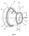
Figur 3- perspektivische Ansicht eines Teils der Verschleißbuchse,
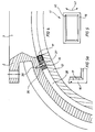
Figur 4- schematisiert ein Teilschnitt vergrößert in der Art nach
Figur 2 mit einer anderen Ausführungsform des Elastomer-Flansches, Figur 5- eine Vorderansicht des Metallmantels, welcher zur stirnseitigen Abschirmung des Elastomer-Flansches verwendet wird,
- Figur 5a
- den Elastomer-Flansch im Detail,
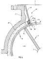
Figur 6- eine weitere Ausführungsform im
Vergleich zu Figur 4 mit Darstellung eines Einsatzteiles.
- Figure 1
- schematically drawn partial section through the left, upper half of a rotary valve according to the invention,
- Figure 2
- a 90 ° cut through a rotary valve,
- Figure 3
- perspective view of part of the wear bushing,
- Figure 4
- schematically shows a partial section enlarged in the manner of Figure 2 with another embodiment of the elastomer flange,
- Figure 5
- a front view of the metal jacket, which is used for the end shielding of the elastomer flange,
- Figure 5a
- the elastomer flange in detail,
- Figure 6
- a further embodiment in comparison to Figure 4 showing an insert.
Wegen der Funktion einer Zellenradschleuse und dem Aufbau der einzelnen Teile wird auf die Offenbarung der DE-A- 37 22 913 verwiesen, die vollinhaltlich von der vorliegenden Erfindung umfasst sein soll.Because of the function of a rotary valve and the structure of the individual parts, reference is made to the disclosure of DE-A-37 22 913, which is to be encompassed in full by the present invention.
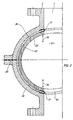
Gemäss der vorliegenden Erfindung besteht nach Figur 1 das Gehäuse aus einer oberen Gehäuseschale 2, die stirnseitig von einem Seitendeckel 1 abgeschlossen ist. Die Gehäuseschale 2 bildet einen oberen Einlauftrichter 3. Im Gehäuse ist eine Welle 4 drehbar gelagert über Lager 10 und zugeordneten Wellendichtringen 11. Die Welle 4 bildet im Bereich des Seitendeckels 1 einen Wellenstumpf 9, an dem die Teile 10,11 angeordnet sind.According to the present invention, according to FIG. 1, the housing consists of an
Die Welle 4 ist drehfest mit einem Zellenrad 5 verbunden, wobei das Zellenrad 5 jeweils an den Stirnseiten eine Seitenscheibe 6 trägt, die ihrerseits fest axial auswärts mit einem Stützring 7 verbunden ist, der seinerseits radial auswärts mit einem Gleitring 8 verbunden ist.The
Die Abdichtung zwischen dem Zellenrad 5 und den zugeordneten Gehäuseschalen 2,22 (vergl. Figur 2) erfolgt erfindungsgemäss durch eine Verschleißbuchse 12, die fest in der Gehäuseschale 2 eingesetzt ist und dort über axial vordere und hintere O-Ringe 13,14 im Bereich einer Gehäusenut abgedichtet ist.The seal between the
Die Verschleißbuchse 12 stützt sich über Lager 10 und Wellendichtringe 11 an der sich drehenden Welle 4 im Bereich des Wellenstumpfes 9 ab.The
Gemäss Figur 1 und 3 besteht die Verschleißbuchse 12 aus einem zylindrischen umlaufenden Ringflansch 25, der an seiner äußeren Stirnfläche den O-Ring 13 und an seiner inneren Stirnfläche den O-Ring 14 trägt. Werkstoffeinstückig mit diesem Ringflansch 25 ist ein seitlicher Büchsenmantel 28 mit dem Ringflansch 25 verbunden, wobei der Büchsenmantel 28 aus einem kreiszylindrischen Teil besteht, welches entsprechende Einschnitte aufweist, um einen oberen Einlauf 29 und einen unteren Auslauf 30 zu bilden. Die Teile 29,30 befinden sich hierbei fluchtend im Bereich des Einlauftrichters 3 bzw. des Auslauftrichters 51.According to Figures 1 and 3, the
Die Einschnitte für den Einlauf und den Auslauf 29,30 gehen jedoch nicht bis zu dem Ringflansch 25, sondern sie lassen in diesem Bereich eine Auflagefläche 32 frei, die - in später noch zu erläuternder Weise - die schwimmende Elastomerschicht trägt, welche die schwimmende Lagerung der Verschleißbuchse 12 in den Gehäuseschalen 2,22 bildet.The incisions for the inlet and the
Die in Figur 3 dargestellte hälftige Verschleißbuchse 12 ist genau symmetrisch zu der vertikalen Scheusenmittelachse 31. Die beiden Teile werden im Bereich der Planfläche 52 aufeinandergestossen und formschlüssig miteinander verbunden. Eine derartige Formschlußverbindung ist beispielsweise in Figur 3 dargestellt. Hierbei sind in den Planflächen 52 Stecklöcher 33 angeordnet, in welche jeweils ein Verbindungszapfen 34 eingreift. Der Verbindungszapfen ragt aus der jeweiligen Planfläche 52 heraus und ragt in das gegenüberliegende Steckloch 33 der gegenüberliegenden, halbseitigen Verschleißbuchse 12 hinein, so daß die beiden Teile ein einheitliches, formschlüssig miteinander verbundenes Teil bilden.The half wear
Es liegt auf der Hand, daß eine derartige hälftige Verschleißbuchse 12 - wie sie in Figur 3 dargestellt ist - sehr leicht zu bearbeiten ist und während der Bearbeitung und der Härtung formstabil bleibt.It is obvious that such a half wear bushing 12 - as shown in Figure 3 - is very easy to machine and remains dimensionally stable during machining and hardening.
Die schwimmende Lagerung der Verschleißbuchse 12 zwischen den Gehäuseschalen 2,22 wird nun anhand der Figuren 1,2 näher beschrieben.The floating mounting of the
Hierbei ist erkennbar, daß auf der Auflagefläche 32 sich der Teil eines Elastomer-Mantels 26 erstreckt, über den sich die Verschleißbuchse 12 auf der Innenseite der Gehäusebohrung abstützt. Die Figur 2 zeigt, daß dieser Elastomer-Mantel 26 rund umläuft und nur im Bereich des Einlauftrichters 3 sowie des Auslauftrichters 51 ausgeschnitten ist. Im Prinzip hat also der Elastomer-Mantel genau die Formgebung, wie sie die seitlichen Büchsenmäntel 28 der Verschleilßbuchse 12 haben.It can be seen here that the part of an
Wichtig ist, daß die Stirnseiten des Elastomer-Mantels, die in den Bereich des Einlauftrichters 3 und des Auslauftrichters 51 ragen, entsprechend armiert sind. Eine derartige Armierung kann beispielsweise über einen Metallmantel 17 mit Federstahlcharakteristik erfolgen, welcher Metallmantel in der Form eines Klammerteils die Stirnseiten einfasst, um diese vor unzulässigem Abrieb zu schützen.It is important that the end faces of the elastomer jacket, which protrude into the area of the
Erfährt nun die Verschleißbuchse 12 ein entsprechendes Verstellspiel, beispielsweise in den Pfeilrichtungen 24, dann läuft die Verschleißbuchse gegen die elastomere Schwimmschicht des Elastomer-Mantels 26 auf und der Minimalabstand 18 (Figur 1) zwischen der Oberkante 44 des Zellenrades und der zugeordneten Innenwandung der Verschleißbuchse bleibt stets gleich. Der Gleitring 8, der aus einem verschleißarmen Material besteht, ist auswechselbar auf dem Stützring 7 angebracht, und zwar derart, daß man den Gleitring 8 auswechseln kann, ohne das Zellenrad 5 ausbauen zu müssen.Now the
Die Oberfläche des Gleitringes 8 bildet also in Verbindung zu der gegenüberliegenden Innenwandung der Verschleißbuchse 12 die Gegenlaufflächen, welche die Leckströmung definieren. Der Abstand 18 zwischen den genannten Flächen kann somit stets gleichbleibend minimal gehalten werden, unabhängig davon, ob das Zellenrad selbst eine Formänderung ausführt oder nicht. Verstellt sich nämlich beispielsweise das Zellenrad 5 in Pfeilrichtung 24 nach Figur 2, dann wird diese Verstellbewegung über das Lager 10,11 und den Wellenstumpf 9 der Verschleißbuchse 12 mitgeteilt. Das Zellenrad 5 und die Verschleißbuchse 12 machen also genau synchrone Bewegungen in Verstellrichtung 24, wodurch die Verstellbewegung der Verschleißbuchse 12 von dem außen liegenden elastomeren Schwimm-Mantel 26 aufgefangen werden.The surface of the
Das Verstellspiel 19 (Figur 1) dient hierbei zum Ausgleich des notwendigen Vertikalspiels der Verstellbuchse 12 im Bereich der Gehäusenut.The adjustment play 19 (FIG. 1) serves to compensate for the necessary vertical play of the
Um eine achsiale Verstellung der Verschleißbuchse 12 zu vermeiden, legt sich die Verschleißbuchse 12 hierbei an den Innenseiten des Seitendeckels 1 jeweils an.In order to avoid an axial adjustment of the
Aus Figur 2 ergibt sich noch, daß das Gehäuse aus zwei hälftig geteilten Schalen besteht, nämlich aus einer oberen Gehäuseschale 2 und einer unteren Gehäuseschale 22. Es ergibt sich hierbei eine Trennfuge 20 in horizontaler Ebene.From Figure 2 it also follows that the housing consists of two halves divided in half, namely an
In Figur 2 ist das Gehäuse mit seiner Gehäusebohrung 21 jedoch ohne eingesetztes Zellenrad 5 gezeichnet.In Figure 2, the housing is drawn with its housing bore 21 without the
Die Figur 4 zeigt eine weitere Ausführungsform der vorliegenden Erfindung, aus der sich ergibt, daß der Elastomer-Mantel 26 nicht voll umfänglich vorhanden ist, sondern nach dem Ausführungsbeispiel gemäss Figur 4 durch einen Elastomer-Flansch 16 ersetzt ist.FIG. 4 shows a further embodiment of the present invention, from which it follows that the
Dieser Elastomer-Flansch 16 befindet sich also nur im Bereich der Auflagefläche 32 der Verschleißbuchse 12 gemäss Figur 3.This
Dieser Elastomer-Flansch 16 bildet somit in der Draufsicht ein rechteckförmiges Teil, wobei an der Einlaufseite ein rechteckförmiges Teil und an der Auslaufseite ebenfalls ein rechteckförmiges Teil angeordnet ist. Beide Teile sind rahmenförmig ausgebildet. Die ungefähre Formgebung ergibt sich aus der Figur 5 bzw. Figur 5a.This
Es handelt sich hierbei um ein Rahmenteil 41, welches in der Art eines Bilderrahmens zusammengefügt ist Auf der Innenseite befindet sich der Metallmantel 17 in Form beispielsweise eines Chrom-Nickel-Materials, welches klammerförmig im Profil in den rahmenförmig umlaufenden Elastomer-Flansch 16 eingehängt ist.This is a
Der Metallmantel 17 ist an den Ecken über Gehrungsstösse 40 aneinandergefügt.The
Aus dem Detail Figur 5a ergeben sich weitere Merkmale dieses Rahmenteils 41.Further features of this
Aus Figur 5a ist erkennbar, daß auf das rahmenförmig umlaufende Kunststoffteil (Elastomer-Flansch 16) der Metallmantel 17 aufgeclipst ist und hierbei die Innenkanten des Elastomer-Flansches umgreift, wie dies im Profil in Figur 4 dargestellt ist. Zur Positionierung des Rahmenteils 41 am Gehäuse sind hierbei Positionierbolzen 37 vorgesehen, die in zugeordnete Bohrungen 37 einerseits des Elastomer-Flansches 16 eingreifen und andererseits in zugeordnete Bohrungen 38 an der Gehäuseseite. Hierdurch wird die Montage dieses Rahmenteils beim Zusammenfügen der äußeren Gehäuseschalen 2,22 erleichtert.It can be seen from FIG. 5a that the
Durch den an der Einlaufseite und Auslaufseite angeordneten Metallmantel, der den Elastomer-Flansch 16 ringsum in diesen Bereichen schützt, wird gewährleistet, daß die Dichtung in diesem Bereich nicht verschleißen kann.The metal jacket arranged on the inlet and outlet sides, which protects the
Der Metallmantel 17 hat jedoch ein derartiges Federvermögen in radialer Richtung des Zellenrades, so daß das geforderte Bewegungsspiel in den Pfeilrichtungen 24 noch aufrecht erhalten bleibt.However, the
Die Befestigung des rahmenförmigen Metallmantels 17 mit dem rahmenförmigen, umlaufenden Elastomerflansch 16 erfolgt über Metallclipse.The frame-shaped
Sobald das Rahmenteil 41 hergestellt ist, muß es noch der sphärischen Innenkrümmung der Gehäuseschalen 2,22 angepasst werden. Dies erfolgt durch Walzen des gesamten Rahmenteils 41 in Pfeilrichtung 42.As soon as the
Durch die Verwendung eines Rahmenteils 41 mit einem Elastomer-Flansch 16 bildet sich somit ein Zwischenraum 35 zwischen der Verschleißbuchse 12 und der zugeordneten Gehäusewandung der Gehäuseschalen 2,22. Dieser Zwischenraum 35 kann mit beliebigen Isoliermaterialien gefüllt sein; er kann auch mit Luft oder mit einem Gas gefüllt sein.By using a
Dieser Zwischenraum 35 wirkt somit geräuschdämmend und temperaturisolierend.This
Die gleiche Wirkung hat im übrigen auch der vorher anhand der Figuren 1 bis 3 erwähnte Elastomer-Mantel 26, wenn auch in niedrigeren Temperaturbereichen.The
Die Figur 6 zeigt eine weitere Ausführungsform der vorliegenden Erfindung, die sich von den vorigen Ausführungsformen dadurch unterscheidet, daß im Bereich der Einlauf- und der Auslaufseite ebenfalls ein Verschleißschutz vorhanden ist.FIG. 6 shows a further embodiment of the present invention, which differs from the previous embodiments in that wear protection is likewise present in the area of the inlet and outlet sides.
Bei diesem Ausführungsbeispiel ist als Beispiel wieder ein vollumfänglich vorhandener Elastomer-Mantel 26 dargestellt, der genauso gut durch das Ausführungsbeispiel nach Figur 4, nämlich durch einen Elastomer-Flansch 16 ersetzt werden kann.In this exemplary embodiment, a fully existing
In Abweichung von den vorher beschriebenen Ausführungsbeispielen ist hier dargestellt, daß auch noch in der Einlaufseite (und auch in analoger Weise in der Auslaufsleite) ein Einsatzteil 45 vorhanden ist, welches im wesentlichen aus einem Einsatzflansch 46, z.B. aus einem Chrom-Nickel-Stahl besteht. Dieser Einsatzflansch 46 deckt somit vollständig die Gehäuseschalen gegenüber einem empfindlichen oder aggressiven Fördermedium ab, so daß es damit möglich ist, relativ billige Materialien für die Gehäuseschalen 2,23 z.B. Aluminiumguß- oder Grauguß zu verwenden und trotzdem im Bereich der gesamten Durchflußstrecke hochverschleißfeste, abriebfeste Materialien verwendet werden können.In deviation from the previously described exemplary embodiments, it is shown here that an
Beim gezeigten Ausführungsbeispiel stösst der Einsatzflansch 46 über eine Schweiss-Stelle 47 mit einem Flansch 48 zusammen. In dem Flansch 48 ist eine Nut eingedreht, in welche ein O-Ring 49 eingelegt ist.In the exemplary embodiment shown, the
Damit stützt sich das gesamte Einsatzteil 45 an einem in Umfangsrichtung an der Verschleißbuchse 12 verlängerten Ansatz 50 ab, so daß eine ausgezeichnete Halterung des Einsatzteils 45 gegeben ist.The
Anhand dieser Zeichnung können nochmals die physikalischen Gegebenheiten erläutert werden, wie sie anhand der vorher beschriebenen Ausführungsbeispiele bereits schon beschrieben wurden.On the basis of this drawing, the physical conditions can be explained again, as have already been described with reference to the previously described exemplary embodiments.
Der hier gezeigte Steg des Zellenrades 5 bildet zusammen mit zeichnerisch nicht näher dargestellten anderen Stegen jeweils eine Zellenradkammer 43. Die Oberkante 44 des Zellenrades bildet den vorher beschriebenen Minimalabstand 18 in Verbindung zur Innenwandung 23 der Verschleißbuchse 12.The web of the
Aufgrund der schwimmenden Lagerung von Verschleißbuchse 12 bleibt somit dieser Minimalabstand 18 stets aufrecht erhalten, unbhängig von Formänderungsspielen, welche das Zellenrad 5 ausführt.Due to the floating mounting of the
Claims (11)
- A housing for a bucket wheel sluice with a housing body comprising an inlet shaft, a bore to receive the bucket wheel and an outlet shaft and two bearing covers closing the bore on the front side, in which an exchangeable cylindrical bush, having perforations at the level of the inlet- and outlet shafts, is inserted into the bore, which bush is constructed as a wear bush and consists of a plurality of parts which are symmetrical to each other, characterised in that
the wear bush (12) consists of two integral components which are in mirror symmetry to a median transverse plane through the vertical central axis (31) of the sluice and have a closed outer circumference lying outside the perforations, and that the wear bush (12) is surrounded on its outer circumference, so formed, at least partially by an elastomeric plastics body, which is constructed as elastomer flange (16) or as elastomer casing (26), which supports the wear bush (12) is a floating manner with respect to the housing shell (2). - A housing according to Claim 1, characterised in that the housing consists of two housing shells (2, 22) which are symmetrical to each other, in which the separating joint (20) extends on a horizontal plane.
- A housing according to Claim 1, characterised in that the wear bush (12) is surrounded over its entire circumference by an elastomeric plastics casing (26) in the manner of a floating bearing, in which the elastomeric plastics casing (26) corresponds in its shaping to the lateral bush casings (28) of the wear bush (12).
- A housing according to Claim 1, characterised in that the wear bush (12) is mounted in a floating manner with respect to the housing shell (2, 22) only on some support faces, in which the elastomeric bearing on the support faces is constructed in the manner of a flange or in the shape of a strip by an elastomer flange (16) (Figure 4).
- A housing according to Claim 1, characterised in that the wear bush (12) has an annular flange (25), running around it cylindrically, which has O rings (13, 14) on the front faces, and that a lateral bush casing (28) is provided, in one piece of material with the annular flange (25), which bush casing (28) has indentations to form the upper inlet (29) and the lower outlet (30), and that a bearing surface (32) is formed on the bush casing (28), which carries the elastomer casing (26) over its entire circumference or in strip form.
- A housing according to Claim 1, characterised in that for the connection of the two wear bushes (12) in the region of their front faces, which are brought to bear on each other, plane surfaces (52) are constructed which have plug holes (33), in which in each case a connecting pin (34) engages.
- A housing according to Claim 1, characterised in that the front faces of the elastomer casing (26), which project into the region of the inlet funnel (3) and of the outlet funnel (51), are constructed so as to be reinforced.
- A housing according to Claim 7, characterised in that the reinforcement is constructed in the form of a clamp piece as metal casing (17) with the characteristic of spring steel.
- A housing according to Claim 4, characterised in that the elastomer flange (16) is constructed so as to be rectangular in plan and hereby forms a frame part (41), in which on the inner side a metal casing (17) is clipped in the form of a clamp onto the profile of the elastomer flange (16) (Figure 5).
- A housing according to Claim 4, characterised in that for the positioning of the elastomer flange (16) or of the frame part (41), positioning bolts (37) are provided which, starting from the elastomer flange (16) engage in associated bores (38) on the housing side (Figure 4).
- A housing according to Claim 1, characterised in that in the region of the inlet and outlet sides of the bucket wheel (5) an insert part (45) is arranged as wear protection to cover the housing shells (2, 22).
Priority Applications (1)
| Application Number | Priority Date | Filing Date | Title |
|---|---|---|---|
| AT91109642T ATE90307T1 (en) | 1990-06-20 | 1991-06-12 | HOUSING FOR A ROTARY WHEEL LOCK. |
Applications Claiming Priority (2)
| Application Number | Priority Date | Filing Date | Title |
|---|---|---|---|
| DE4019627 | 1990-06-20 | ||
| DE4019627A DE4019627C3 (en) | 1990-06-20 | 1990-06-20 | Housing for a rotary valve |
Publications (3)
| Publication Number | Publication Date |
|---|---|
| EP0462500A1 EP0462500A1 (en) | 1991-12-27 |
| EP0462500B1 EP0462500B1 (en) | 1993-06-09 |
| EP0462500B2 true EP0462500B2 (en) | 1995-09-06 |
Family
ID=6408719
Family Applications (1)
| Application Number | Title | Priority Date | Filing Date |
|---|---|---|---|
| EP91109642A Expired - Lifetime EP0462500B2 (en) | 1990-06-20 | 1991-06-12 | Housing for a rotary valve |
Country Status (3)
| Country | Link |
|---|---|
| EP (1) | EP0462500B2 (en) |
| AT (1) | ATE90307T1 (en) |
| DE (2) | DE4019627C3 (en) |
Families Citing this family (9)
| Publication number | Priority date | Publication date | Assignee | Title |
|---|---|---|---|---|
| DE4244655C2 (en) * | 1992-05-06 | 2000-05-31 | Reimelt Dietrich Kg | Cell wheel lock |
| DE4214467C2 (en) * | 1992-05-06 | 2001-07-26 | Reimelt Dietrich Kg | Cell wheel lock |
| NO180115C (en) * | 1993-12-07 | 1997-02-19 | Ameco International As | Rotary locking device equipped with wear coating and method for making the wear coating |
| DE4405828A1 (en) * | 1994-02-23 | 1995-08-24 | Krupp Polysius Ag | Cell wheel lock |
| DE4411811C2 (en) * | 1994-04-06 | 1998-08-27 | Motan Fuller Verfahrenstechnik | Housing lining for a rotary valve |
| DE19738122A1 (en) * | 1997-09-01 | 1999-03-11 | Waeschle Maschf Gmbh | Cell wheel lock for dosing bulk goods |
| DE19802788A1 (en) * | 1998-01-26 | 1999-08-05 | Waeschle Gmbh | Cellular vane sluice for feeding or dosing bulk material in pneumatic supply line |
| DE102005048734A1 (en) * | 2005-10-12 | 2007-04-19 | Coperion Waeschle Gmbh & Co. Kg | Housing for a cellular wheel lock |
| DE102006043252B4 (en) * | 2006-09-11 | 2019-06-19 | Coperion Gmbh | rotary |
Family Cites Families (5)
| Publication number | Priority date | Publication date | Assignee | Title |
|---|---|---|---|---|
| GB1161204A (en) * | 1965-09-17 | 1969-08-13 | Coal Industry Patents Ltd | Pneumatic Stowing Machines. |
| DE2350033C3 (en) * | 1973-10-05 | 1982-04-01 | Jaudt, Andreas, 8901 Königsbrunn | Cell lock |
| DE2732199A1 (en) * | 1977-07-16 | 1979-01-25 | Andreas Jaudt | VARIABLE WHEEL LOCK WITH INFLATABLE WHEEL POCKETS |
| GB2192164B (en) * | 1986-07-04 | 1989-12-13 | Coal Ind | Improvements in or relating to rotary valves |
| DE3722913A1 (en) * | 1987-07-10 | 1989-01-26 | Waeschle Maschf Gmbh | Housing for a cellular wheel sluice |
-
1990
- 1990-06-20 DE DE4019627A patent/DE4019627C3/en not_active Expired - Fee Related
-
1991
- 1991-06-12 DE DE9191109642T patent/DE59100141D1/en not_active Expired - Fee Related
- 1991-06-12 EP EP91109642A patent/EP0462500B2/en not_active Expired - Lifetime
- 1991-06-12 AT AT91109642T patent/ATE90307T1/en not_active IP Right Cessation
Also Published As
| Publication number | Publication date |
|---|---|
| DE4019627C2 (en) | 1992-12-24 |
| DE4019627C3 (en) | 1998-04-23 |
| ATE90307T1 (en) | 1993-06-15 |
| DE4019627A1 (en) | 1992-01-09 |
| EP0462500A1 (en) | 1991-12-27 |
| DE59100141D1 (en) | 1993-07-15 |
| EP0462500B1 (en) | 1993-06-09 |
Similar Documents
| Publication | Publication Date | Title |
|---|---|---|
| DE19651112C2 (en) | Sealing device for an engine piston rod | |
| EP0462500B2 (en) | Housing for a rotary valve | |
| CH660407A5 (en) | SEALING RING FOR PISTON RODS. | |
| EP0009269A1 (en) | Light-metal piston for internal combustion engines | |
| DE3718286A1 (en) | ROLE FOR SUBSTANCES | |
| DE3213809C2 (en) | Cassette seal | |
| DE69309909T2 (en) | WEAPON SEAL WITH RADIAL COMPRESSIBLE SUPPORT RING | |
| DE2847252C3 (en) | Arrangement for sealing the joint between two stator parts of a. Turbo engine | |
| DE3217118C1 (en) | Sealing arrangement for shafts | |
| DE3321597C2 (en) | Mechanical seal | |
| EP0462501B1 (en) | Rotary valve with clearance sealings for feeding bulk material into pneumatic conveyors | |
| DE2853146C2 (en) | Foil slide bearings, in particular for chemical pumps | |
| EP3485185B1 (en) | Gas seal | |
| DE4323470C2 (en) | Sealing arrangement for sealing a shaft bushing on the bulkhead of a ship | |
| EP4328026B1 (en) | Hard seal ring with sliding running surface and sliding running seal device | |
| DE3876343T2 (en) | MAGNETIC SEALING DEVICE. | |
| DE19506683C2 (en) | Piston rod seal | |
| DE2925237A1 (en) | Butterfly stop valve assembly - has housing split on radial plane through spindle with spring sleeves on halves | |
| DE806077C (en) | Bearings for shafts with a bearing surface consisting of strips | |
| DE20306899U1 (en) | Rolling bearing for wind power plant, for example, has segmented flange with run-on face which for each bearing segment in proximity of end faces assumes form of transition profile | |
| DE10034195C1 (en) | Dredger pump has welded sheet metal pump wheel provided with 2 discs having axially projecting blades | |
| DE1914800C2 (en) | Sealing ring for use in stuffing boxes | |
| DE1012183B (en) | Centrifugal pump, especially for the promotion of abrasive Trueben, Schleemmen od. Like. | |
| EP1655522A1 (en) | Piston ring | |
| DE821751C (en) | Arrangement of seals for rods, shafts or the like in the form of a sealing ring |
Legal Events
| Date | Code | Title | Description |
|---|---|---|---|
| PUAI | Public reference made under article 153(3) epc to a published international application that has entered the european phase |
Free format text: ORIGINAL CODE: 0009012 |
|
| AK | Designated contracting states |
Kind code of ref document: A1 Designated state(s): AT BE CH DE DK FR GB IT LI LU NL SE |
|
| 17P | Request for examination filed |
Effective date: 19911203 |
|
| 17Q | First examination report despatched |
Effective date: 19921117 |
|
| GRAA | (expected) grant |
Free format text: ORIGINAL CODE: 0009210 |
|
| AK | Designated contracting states |
Kind code of ref document: B1 Designated state(s): AT BE CH DE DK FR GB IT LI LU NL SE |
|
| PG25 | Lapsed in a contracting state [announced via postgrant information from national office to epo] |
Ref country code: SE Effective date: 19930609 Ref country code: DK Free format text: LAPSE BECAUSE OF NON-PAYMENT OF DUE FEES Effective date: 19930609 Ref country code: BE Effective date: 19930609 |
|
| REF | Corresponds to: |
Ref document number: 90307 Country of ref document: AT Date of ref document: 19930615 Kind code of ref document: T |
|
| PG25 | Lapsed in a contracting state [announced via postgrant information from national office to epo] |
Ref country code: AT Effective date: 19930612 |
|
| PG25 | Lapsed in a contracting state [announced via postgrant information from national office to epo] |
Ref country code: LU Free format text: LAPSE BECAUSE OF NON-PAYMENT OF DUE FEES Effective date: 19930630 |
|
| PLBI | Opposition filed |
Free format text: ORIGINAL CODE: 0009260 |
|
| REF | Corresponds to: |
Ref document number: 59100141 Country of ref document: DE Date of ref document: 19930715 |
|
| ITF | It: translation for a ep patent filed | ||
| 26 | Opposition filed |
Opponent name: BUEHLER AG Effective date: 19930708 |
|
| GBT | Gb: translation of ep patent filed (gb section 77(6)(a)/1977) |
Effective date: 19930914 |
|
| ET | Fr: translation filed | ||
| NLR1 | Nl: opposition has been filed with the epo |
Opponent name: BUHLER AG. |
|
| PUAH | Patent maintained in amended form |
Free format text: ORIGINAL CODE: 0009272 |
|
| STAA | Information on the status of an ep patent application or granted ep patent |
Free format text: STATUS: PATENT MAINTAINED AS AMENDED |
|
| ITF | It: translation for a ep patent filed | ||
| 27A | Patent maintained in amended form |
Effective date: 19950906 |
|
| AK | Designated contracting states |
Kind code of ref document: B2 Designated state(s): AT BE CH DE DK FR GB IT LI LU NL SE |
|
| REG | Reference to a national code |
Ref country code: CH Ref legal event code: AEN |
|
| ET3 | Fr: translation filed ** decision concerning opposition | ||
| NLR2 | Nl: decision of opposition | ||
| GBTA | Gb: translation of amended ep patent filed (gb section 77(6)(b)/1977) |
Effective date: 19951025 |
|
| NLR3 | Nl: receipt of modified translations in the netherlands language after an opposition procedure | ||
| NLT1 | Nl: modifications of names registered in virtue of documents presented to the patent office pursuant to art. 16 a, paragraph 1 |
Owner name: MOTAN-FUELLER VERFAHRENSTECHNIK GMBH |
|
| PGFP | Annual fee paid to national office [announced via postgrant information from national office to epo] |
Ref country code: DE Payment date: 19970508 Year of fee payment: 7 |
|
| PGFP | Annual fee paid to national office [announced via postgrant information from national office to epo] |
Ref country code: GB Payment date: 19970605 Year of fee payment: 7 |
|
| PGFP | Annual fee paid to national office [announced via postgrant information from national office to epo] |
Ref country code: FR Payment date: 19970625 Year of fee payment: 7 Ref country code: CH Payment date: 19970625 Year of fee payment: 7 |
|
| PGFP | Annual fee paid to national office [announced via postgrant information from national office to epo] |
Ref country code: NL Payment date: 19970630 Year of fee payment: 7 |
|
| PG25 | Lapsed in a contracting state [announced via postgrant information from national office to epo] |
Ref country code: GB Free format text: LAPSE BECAUSE OF NON-PAYMENT OF DUE FEES Effective date: 19980612 |
|
| PG25 | Lapsed in a contracting state [announced via postgrant information from national office to epo] |
Ref country code: LI Free format text: LAPSE BECAUSE OF NON-PAYMENT OF DUE FEES Effective date: 19980630 Ref country code: CH Free format text: LAPSE BECAUSE OF NON-PAYMENT OF DUE FEES Effective date: 19980630 |
|
| PG25 | Lapsed in a contracting state [announced via postgrant information from national office to epo] |
Ref country code: NL Free format text: LAPSE BECAUSE OF NON-PAYMENT OF DUE FEES Effective date: 19990101 |
|
| GBPC | Gb: european patent ceased through non-payment of renewal fee |
Effective date: 19980612 |
|
| REG | Reference to a national code |
Ref country code: CH Ref legal event code: PL |
|
| PG25 | Lapsed in a contracting state [announced via postgrant information from national office to epo] |
Ref country code: FR Free format text: LAPSE BECAUSE OF NON-PAYMENT OF DUE FEES Effective date: 19990226 |
|
| NLV4 | Nl: lapsed or anulled due to non-payment of the annual fee |
Effective date: 19990101 |
|
| PG25 | Lapsed in a contracting state [announced via postgrant information from national office to epo] |
Ref country code: DE Free format text: LAPSE BECAUSE OF NON-PAYMENT OF DUE FEES Effective date: 19990401 |
|
| REG | Reference to a national code |
Ref country code: FR Ref legal event code: ST |
|
| PG25 | Lapsed in a contracting state [announced via postgrant information from national office to epo] |
Ref country code: IT Free format text: LAPSE BECAUSE OF NON-PAYMENT OF DUE FEES;WARNING: LAPSES OF ITALIAN PATENTS WITH EFFECTIVE DATE BEFORE 2007 MAY HAVE OCCURRED AT ANY TIME BEFORE 2007. THE CORRECT EFFECTIVE DATE MAY BE DIFFERENT FROM THE ONE RECORDED. Effective date: 20050612 |