EP0462362A2 - Optische Verbindung für Lichtwellenleiter - Google Patents
Optische Verbindung für Lichtwellenleiter Download PDFInfo
- Publication number
- EP0462362A2 EP0462362A2 EP91103812A EP91103812A EP0462362A2 EP 0462362 A2 EP0462362 A2 EP 0462362A2 EP 91103812 A EP91103812 A EP 91103812A EP 91103812 A EP91103812 A EP 91103812A EP 0462362 A2 EP0462362 A2 EP 0462362A2
- Authority
- EP
- European Patent Office
- Prior art keywords
- optical
- plug
- bores
- optical connection
- coupling element
- Prior art date
- Legal status (The legal status is an assumption and is not a legal conclusion. Google has not performed a legal analysis and makes no representation as to the accuracy of the status listed.)
- Withdrawn
Links
Images




Classifications
-
- G—PHYSICS
- G02—OPTICS
- G02B—OPTICAL ELEMENTS, SYSTEMS OR APPARATUS
- G02B6/00—Light guides; Structural details of arrangements comprising light guides and other optical elements, e.g. couplings
- G02B6/24—Coupling light guides
- G02B6/36—Mechanical coupling means
- G02B6/38—Mechanical coupling means having fibre to fibre mating means
- G02B6/3807—Dismountable connectors, i.e. comprising plugs
- G02B6/381—Dismountable connectors, i.e. comprising plugs of the ferrule type, e.g. fibre ends embedded in ferrules, connecting a pair of fibres
- G02B6/3826—Dismountable connectors, i.e. comprising plugs of the ferrule type, e.g. fibre ends embedded in ferrules, connecting a pair of fibres characterised by form or shape
- G02B6/383—Hermaphroditic connectors, i.e. two identical plugs mating with one another, each plug having both male and female diametrically opposed engaging parts
-
- G—PHYSICS
- G02—OPTICS
- G02B—OPTICAL ELEMENTS, SYSTEMS OR APPARATUS
- G02B6/00—Light guides; Structural details of arrangements comprising light guides and other optical elements, e.g. couplings
- G02B6/24—Coupling light guides
- G02B6/26—Optical coupling means
- G02B6/32—Optical coupling means having lens focusing means positioned between opposed fibre ends
-
- G—PHYSICS
- G02—OPTICS
- G02B—OPTICAL ELEMENTS, SYSTEMS OR APPARATUS
- G02B6/00—Light guides; Structural details of arrangements comprising light guides and other optical elements, e.g. couplings
- G02B6/24—Coupling light guides
- G02B6/36—Mechanical coupling means
- G02B6/38—Mechanical coupling means having fibre to fibre mating means
- G02B6/3807—Dismountable connectors, i.e. comprising plugs
- G02B6/3873—Connectors using guide surfaces for aligning ferrule ends, e.g. tubes, sleeves, V-grooves, rods, pins, balls
- G02B6/3874—Connectors using guide surfaces for aligning ferrule ends, e.g. tubes, sleeves, V-grooves, rods, pins, balls using tubes, sleeves to align ferrules
- G02B6/3878—Connectors using guide surfaces for aligning ferrule ends, e.g. tubes, sleeves, V-grooves, rods, pins, balls using tubes, sleeves to align ferrules comprising a plurality of ferrules, branching and break-out means
-
- G—PHYSICS
- G02—OPTICS
- G02B—OPTICAL ELEMENTS, SYSTEMS OR APPARATUS
- G02B6/00—Light guides; Structural details of arrangements comprising light guides and other optical elements, e.g. couplings
- G02B6/24—Coupling light guides
- G02B6/36—Mechanical coupling means
- G02B6/38—Mechanical coupling means having fibre to fibre mating means
- G02B6/3807—Dismountable connectors, i.e. comprising plugs
- G02B6/389—Dismountable connectors, i.e. comprising plugs characterised by the method of fastening connecting plugs and sockets, e.g. screw- or nut-lock, snap-in, bayonet type
Definitions
- connection of two optical fibers is generally made by a plug connection.
- optical connection of several optical fibers there is the problem that the optical fibers must be precisely fixed and adjusted in the connection, since the end faces of the optical fibers to be connected to one another must lie exactly opposite one another in the connection area.
- the invention is based on the object of specifying an optical connection for optical waveguides which enables precise fixing and adjustment of the optical waveguides to be connected to one another and which also offers the possibility of easily assembling the optical connection and of easily replacing parts of the optical connection.
- This object is achieved according to the invention by an optical connection with the features of claim 1.
- FIG. 1 shows an optical fiber cable 1 with an optical fiber (optical wire) and an optical connector 2, which is connected to the optical fiber cable 1.
- the optical connector 2 consists of a connector body 3, a union nut 4 and a connector pin 5 in which the optical waveguide is adjusted and fixed.
- the optical fiber cable (optical cable) to be connected to the optical fiber cable 1 and not shown in FIG. 1 also has a plug, which is generally referred to as a mating connector.
- the mating connector can be designed in the same way as the connector of Figure 1 or it can also have a different design. It is only essential that the plug and mating connector fit together and result in a common plug connection.
- a body 6 which serves to receive an optical lens or an optical lens system and can be connected to the optical connector 2.
- a detachable connection is recommended, which is produced, for example, by plugging the body 6 onto the plug pin 5.
- the plugged-on body 6 is screwed to the union nut 4.
- the lens (lens system) located in the body 6 has the task of expanding the light beam emerging from the optical waveguide (fiber) and continuing it as a quasi-parallel beam.
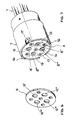
- FIG. 3 shows a coupling element 7 according to the invention, which serves to accommodate a plurality of optical connectors 2 with a lens body 6 (lens attachment).
- the coupling element 7 serves to receive four optical plugs 2 with lens bodies 6.
- the coupling element 7 in FIG. 3 is provided with four through bores (8 ', 8'',8''', 8 ''').
- the optical connectors 2 according to FIG. 4, which shows an example of a connector 2 are inserted from one side (from right to left) through the bores (8 ', 8' ', 8' '', 8 '''') of the coupling element 7, namely according to FIG. 5 (upper part) to such an extent that they appear on the other side of the coupling element 7 and onto the inserted plug 2 according to FIG. 5 (example for a plug) Lens body 6 (lens attachments) can be attached or screwed on.
- the plugs 2 are pushed back into the bores (8 ', 8' ', 8' '', 8 ''', 8 '' '), as shown in the lower part of FIG. 5 for a plug.
- the plug is pushed back into the associated bore until it stops with a spring ring 14 which is located between the lower end face of the lens body 6 and a stop face 9.
- the stop 9 in the interior of the bores is formed by a two-stage bore or by sleeves 10 which are introduced into the bores according to FIGS. 4 and 5.
- the stopper 9 in the bores fixes the plug 2 or the lens body 6 in the bores (8 ', 8' ', 8' '', 8 '' '') so that the end faces of the lens body are in a certain plane lie.
- the diameter of the bores (8 ', 8' ', 8' '', 8 '' '') is dimensioned so that the lens body 6 has a snug fit in the bores.
- the position of the holes is chosen so that no optics can be destroyed in the catch area of the claws.
- the coupling element 7 is closed on the side on which the light emerges with a cover 11 which, according to the four bores in the coupling element 7 according to FIG. 6, has four bores (12 ', 12'',12''', 12 '''), which the Let light emerge from the lens bodies 6.
- a projection 13 is provided on the upper end face of the lens body 6 according to FIG. 2, which protrudes from the upper end face of the lens body 6 and has a smaller diameter than the entire top face.
- the diameters of the cover bores (12 ', 12'',12''', 12 ''') are adapted to the diameters of the projections 13. If the coupling element 7 is closed by the cover 11 according to FIG. 7, the projections 13 of the lens body 6 extend into the bores (12 ', 12'',12''', 12 ''') of the cover 11 while the lid 11 presses on the areas of the end faces of the lens bodies 6 surrounding the projections 13. The lens body 6 is thus fixed on one side by the stops (9) located in the bores (8 ', 8'',8''', 8 '''') of the coupling element 7, and on the other side the cover 11.
- spring elements 14 for example O-rings
- the spring elements 14 ensure that the lens body 6 is pressed against the lid 11.
- the cover 11 is screwed to the coupling element 7.
- the opposing lens systems In the stretched state, the opposing lens systems must not touch each other, but there must be a small gap between the end faces of the lens systems.
- Those optical cables which are to be connected to the optical cables located in the coupling element 7 are also arranged in a coupling element (15) (left coupling element) in the connection area according to FIG. 8, in general in the same way as in connection has been described with Figures 1 to 7.
- the coupling element 7 according to FIG. 8 contains claws 16 and recesses 17 and the coupling element 15 has recesses 18 and claws 19. In the state of the connection, the claws of the two coupling elements engage in the corresponding recesses in Coupling elements.
- FIG. 9 shows the coupling elements 7 and 15 connected to one another.
- the connection between the two coupling elements (7, 15) can also be fixed, but a fixed connection should be releasable, for example by using a screw connection or a bayonet lock.
- the invention has the advantage that several optical channels can be connected to one another at the same time by a plug-in process.
- environmental influences such as dew or dirt are less noticeable.
- Lens systems also enable greater mechanical tolerances.
- the use of the coupling elements according to the invention enables the use of conventional plugs or lines with standard plugs and can be fitted from the front without the coupling element (sleeve) must be removed.
- the invention enables modular assembly, specifically with regard to the lines, plugs, lens attachments or the entire system.
- the invention further enables installation in systems without fiber optic cables and requires a relatively small adjustment effort. Since the cover and the end faces of the lens systems lie in one plane, the end faces and thus the lens systems can be cleaned without any problems.
Landscapes
- Physics & Mathematics (AREA)
- General Physics & Mathematics (AREA)
- Optics & Photonics (AREA)
- Mechanical Coupling Of Light Guides (AREA)
Abstract
Description
- In der Lichtwellenleitertechnik erfolgt die Verbindung von zwei Lichtwellenleitern im allgemeinen durch eine Steckverbindung. Vor allem bei der optischen Verbindung von mehreren Lichtwellenleitern besteht das Problem, daß die Lichtwellenleiter in der Verbindung genau fixiert und justiert sein müssen, da die Stirnflächen der miteinander zu verbindenden Lichtwellenleiter im Verbindungsbereich einander genau gegenüber liegen müssen.
- Der Erfindung liegt die Aufgabe zugrunde, eine optische Verbindung für Lichtwellenleiter anzugeben, die eine genaue Fixierung und Justierung der miteinander zu verbindenden Lichtwellenleiter ermöglicht und die außerdem die Möglichkeit bietet, die optische Verbindung leicht zu montieren und Teile der optischen Verbindung leicht auszutauschen. Diese Aufgabe wird erfindungsgemäß durch eine optische Verbindung mit den Merkmalen des Anspruchs 1 gelöst.
- Die Erfindung wird im folgenden an einem Ausführungsbeispiel erläutert.
- Die Figur 1 zeigt ein Lichtwellenleiterkabel 1 mit einem Lichtwellenleiter (optische Ader) sowie einem optischen Stecker 2, der mit dem Lichtwellenleiterkabel 1 verbunden ist. Der optische Stecker 2 besteht im Ausführungsbeispiel der Figur 1 aus einem Steckerkörper 3, einer Überwurfmutter 4 und einem Steckerstift 5, in dem der Lichtwellenleiter justiert und fixiert ist.
- Das durch das Lichtwellenleiterkabel 1 transportierte Licht tritt an der Stirnseite des Steckerstiftes 5 aus. Das mit dem Lichtwellenleiterkabel 1 zu verbindende und in der Figur 1 nicht dargestellte Lichtwellenleiterkabel (optische Kabel) weist ebenfalls einen Stecker auf, der im allgemeinen als Gegenstecker bezeichnet wird. Der Gegenstecker kann in derselben Weise ausgebildet sein wie der Stecker der Figur 1 oder er kann auch eine andere Bauart aufweisen. Wesentlich ist nur, daß Stecker und Gegenstecker zusammenpassen und eine gemeinsame Steckverbindung ergeben.
- Bei der Anordnung der Figur 2 ist zusätzlich zum optischen Stecker 2 der Figur 1 ein Körper 6 vorgesehen, der zur Aufnahme einer optischen Linse oder eines optischen Linsensystems dient und mit dem optischen Stecker 2 verbindbar ist. Zum Verbinden des Körpers 6 mit dem optischen Stecker 2 empfiehlt sich eine lösbare Verbindung, die zum Beispiel durch Aufstecken des Körpers 6 auf den Steckerstift 5 hergestellt wird. Im Ausführungsbeispiel der Figur 2 ist der aufgesteckte Körper 6 mit der Überwurfmutter 4 verschraubt. Die im Körper 6 befindliche Linse (Linsensystem) hat die Aufgabe, den aus dem Lichtwellenleiter (Faser) austretenden Lichtstrahl aufzuweiten und als quasiparalleles Strahlenbündel weiterzuführen.
- Die Figur 3 (3a, 3b) zeigt ein Kopplungselement 7 nach der Erfindung, welches zur Aufnahme mehrerer optischer Stecker 2 mit Linsenkörper 6 (Linsenaufsatz) dient. Im Ausführungsbeispiel der Figur 3 dient das Kopplungslement 7 zur Aufnahme von vier optischen Steckern 2 mit Linsenkörpern 6. Um die vier optischen Stecker 2 mit Linsenkörper 6 aufnehmen zu können, ist das Kopplungselement 7 der Figur 3 mit vier durchgehenden Bohrungen (8', 8'', 8''', 8'''') versehen.
- Zur Bestückung des Kopplungselementes 7 werden die optischen Stecker 2 gemäß der Figur 4, die ein Beispiel für einen Stecker 2 zeigt, von einer Seite aus (von rechts nach links) durch die Bohrungen (8', 8'', 8''', 8'''') des Kopplungselementes 7 geschoben, und zwar gemäß Figur 5 (oberer Teil) so weit, daß sie auf der anderen Seite des Kopplungselementes 7 erscheinen und auf die durchgeschobenen Stecker 2 gemäß der Figur 5 (Beispiel für einen Stecker) die Linsenkörper 6 (Linsenaufsätze) aufgesteckt bzw. aufgeschraubt werden können. Nach dem Aufstecken bzw. Aufschrauben der Linsenkörper 6 werden die Stecker 2 in die Bohrungen (8', 8'', 8''', 8'''') zurückgeschoben, wie es die Figur 5 im unteren Teil für einen Stecker zeigt. Das Zurückschieben des Steckers in die dazugehörige Bohrung erfolgt bis zum Anschlag mit einem Federring 14, der sich zwischen der unteren Stirnfläche des Linsenkörpers 6 und einer Anschlagfläche 9 befindet. Der Anschlag 9 im Inneren der Bohrungen wird durch eine Zweistufenbohrung oder durch Hülsen 10 gebildet, die in die Bohrungen gemäß den Figuren 4 und 5 eingebracht sind. Durch den Anschlag 9 in den Bohrungen werden die Stecker 2 bzw. die Linsenkörper 6 in den Bohrungen (8', 8'', 8''', 8'''') so fixiert, daß die Stirnflächen der Linsenkörper in einer bestimmten Ebene liegen. Der Durchmesser der Bohrungen (8', 8'', 8''', 8'''') ist so bemessen, daß die Linsenkörper 6 einen Paßsitz in den Bohrungen haben. Außerdem ist die Lage der Bohrungen so gewählt, daß im Fangbereich der Klauen keine Optik zerstört werden kann.
- Wie die Figur 7 zeigt, wird das Kopplungselement 7 auf derjenigen Seite, auf der das Licht austritt, mit einem Deckel 11 abgeschlossen, der entsprechend den vier Bohrungen im Kopplungselement 7 gemäß der Figur 6 vier Bohrungen (12', 12'', 12''', 12'''') aufweist, die das Licht aus den Linsenkörpern 6 austreten lassen. Um die Linsenkörper 6 auch im Bereich ihrer oberen Stirnflächen mit Hilfe des Deckels 11 fixieren zu können, ist auf der oberen Stirnseite des Linsenkörpers 6 gemäß der Figur 2 ein Vorsprung 13 vorgesehen, der aus der oberen Stirnfläche der Linsenkörper 6 heraustritt und einen kleineren Durchmesser hat als die gesamte obere Stirnfläche. Die Durchmesser der Deckelbohrungen (12', 12'', 12''', 12'''') sind den Durchmessern der Vorsprünge 13 angepaßt. Ist das Kopplungselement 7 gemäß der Figur 7 durch den Deckel 11 abgeschlossen, so erstrecken sich die Vorsprünge 13 der Linsenkörper 6 in die Bohrungen (12', 12'', 12''', 12'''') des Deckels 11, während der Deckel 11 auf die die Vorsprünge 13 umgebenden Bereiche der Stirnflächen der Linsenkörper 6 drückt. Die Fixierung der Linsenkörper 6 erfolgt also auf der einen Seite durch die in den Bohrungen (8', 8'', 8''', 8'''') des Kopplungselementes 7 befindlichen Anschläge (9), und auf der anderen Seite durch den Deckel 11.
- Gemäß einer Weiterbildung der Erfindung befinden sich, wie bereits erwähnt, in den Bohrungen (8', 8'', 8''', 8'''') des Kopplungselementes 7 Federelemente 14 (z. B. O-Ringe), die gemäß den Figuren 4 und 5 zwischen den Anschlagflächen 9 und den Linsenkörpern angeordnet sind. Die Federelemente 14 sorgen dafür, daß die Linsenkörper 6 gegen den Deckel 11 gedrückt werden. Der Deckel 11 ist im Ausführungsbeispiel mit dem Kopplungselement 7 verschraubt. Im gestreckten Zustand dürfen die einander gegenüberliegenden Linsensysteme einander nicht berühren, sondern es muß ein kleiner Spalt zwischen den Stirnflächen der Linsensysteme vorhanden sein. Um diese Bedingung zu gewährleisten, liegt im montierten Zustand (Deckel 11 aufgeschraubt) die Ebene, die durch die nach aussen weisende Stirnfläche des Deckels 11 und durch die Stirnflächen der Linsensysteme gebildet wird, etwas tiefer als diejenige Ebene, in der sich der obere Rand des Kopplungselementes (Hülse) 7 befindet. Dieser Sachverhalt ist den Figuren 7 und 8 zu entnehmen.
- Diejenigen optischen Kabel, die mit den im Kopplungselement 7 befindlichen optischen Kabeln zu verbinden sind, sind im Verbindungsbereich gemäß der Figur 8 ebenfalls in einem Kopplungselement (15) (linkes Kopplungselement) angeordnet, und zwar im allgemeinen in der gleichen Weise, wie es in Verbindung mit den Figuren 1 bis 7 beschrieben wurde. Zur Herstellung einer lösbaren Verbindung zwischen den beiden Kopplungselementen 7 und 15 enthält das Kopplungselement 7 gemäß der Figur 8 Klauen 16 und Ausnehmungen 17 und das Kopplungselement 15 Ausnehmungen 18 und Klauen 19. Im Zustand der Verbindung greifen die Klauen der beiden Kopplungselemente in die entsprechenden Ausnehmungen der Kopplungselemente ein.
- Die Figur 9 zeigt die miteinander verbundenen Kopplungselemente 7 und 15. Die Verbindung zwischen den beiden Kopplungselementen (7, 15) kann auch fest sein, doch soll eine feste Verbindung wieder lösbar sein, und zwar beispielsweise durch Verwendung einer Schraubverbindung oder eines Bajonettverschlusses.
- Die Erfindung hat den Vorteil, daß durch einen Steckvorgang gleichzeitig mehrere optische Kanäle miteinander verbunden werden können. Bei Verwendung von Linsensystemen machen sich Umwelteinflüsse wie Tau oder Schmutz weniger bemerkbar. Linsensysteme ermöglichen auch größere mechanische Toleranzen. Die Verwendung der erfindungsgemäßen Kopplungselemente ermöglicht die Benutzung üblicher Stecker bzw. Leitungen mit Standard-Steckern sowie eine Bestückung von vorne, ohne daß das Kopplungselement (Hülse) ausgebaut werden muß. Die Erfindung ermöglicht bei Defekten eine modulare Bestückung, und zwar bezüglich der Leitungen, Stecker, Linsenaufsätze oder des ganzen Systems. Die Erfindung ermöglicht weiterhin einen Einbau in Systeme ohne LWL-Kabel, und erfordert einen relativ geringen Justieraufwand. Da der Deckel und die Stirnflächen der Linsensysteme in einer Ebene liegen, ist eine unproblematische Reinigung der Stirnflächen und damit der Linsensysteme möglich.
Claims (11)
- Optische Verbindung für Lichtwellenleiter, bei der die Lichtwellenleiter duch eine Steckverbindung miteinander verbunden werden, dadurch gekennzeichnet, daß Kopplungselemente vorgesehen sind, in die die Steckverbindungselemente einsteckbar sind.
- Optische Verbindung nach Anspruch 1, dadurch gekennzeichnet, daß ein Kopplungselement für die Stecker der Steckverbindung und ein Kopplungselement für die Gegenstecker der Steckverbindung vorgesehen sind.
- Optische Verbindung nach Anspruch 1 oder 2, dadurch gekennzeichnet, daß ein Kopplungselement aus einem Körper besteht, der soviele Bohrungen aufweist, wie Steckverbindungen vorgesehen sind.
- Optische Verbindung nach einem der Ansprüche 1 bis 3, dadurch gekennzeichnet, daß die Bohrungen im Kopplungselement Stufenbohrungen aufweisen.
- Optische Verbindung nach einem der Ansprüche 1 bis 4, dadurch gekennzeichnet, daß zur Erzielung einer Stufenbohrung in die Bohrungen Buchsen eingebracht sind.
- Optische Verbindung nach einem der Ansprüche 1 bis 5, dadurch gekennzeichnet, daß die Steckverbindungen Steckerstifte aufweisen und daß auf die Steckerstifte Linsenkörper aufgebracht sind.
- Optische Verbindung nach einem der Ansprüche 1 bis 6, dadurch gekennzeichnet, daß die Übergangsstelle zwischen den unterschiedlichen Bohrungen im Kopplungselement als Anschlag für die Linsenkörper dient.
- Optische Verbindung nach einem der Ansprüche 1 bis 7, dadurch gekennzeichnet, daß zwischen dem Anschlag und der Stirnfläche des Linsenkörpers ein Federelement vorgesehen ist.
- Optische Verbindung nach einem der Ansprüche 1 bis 8, dadurch gekennzeichnet, daß die Kopplungselemente durch einen Deckel abgeschlossen sind, der Bohrungen entsprechend der Anzahl der Bohrungen im Kopplungselement aufweist.
- Optische Verbindung nach einem der Ansprüche 1 bis 9, dadurch gekennzeichnet, daß die Linsenkörper Vorsprünge aufweisen, die in Bohrungen des Deckels eingreifen.
- Optische Verbindung nach einem der Ansprüche 1 bis 10, dadurch gekennzeichnet, daß die Kopplungselemente Ausnehmungen und Klauen aufweisen, die zur Vebindung von Kopplungselementen dienen.
Applications Claiming Priority (2)
| Application Number | Priority Date | Filing Date | Title |
|---|---|---|---|
| DE4019733 | 1990-06-21 | ||
| DE19904019733 DE4019733A1 (de) | 1990-06-21 | 1990-06-21 | Optische verbindung fuer lichtwellenleiter |
Publications (2)
| Publication Number | Publication Date |
|---|---|
| EP0462362A2 true EP0462362A2 (de) | 1991-12-27 |
| EP0462362A3 EP0462362A3 (en) | 1992-06-03 |
Family
ID=6408766
Family Applications (1)
| Application Number | Title | Priority Date | Filing Date |
|---|---|---|---|
| EP19910103812 Withdrawn EP0462362A3 (en) | 1990-06-21 | 1991-03-13 | Optical connection for light guides |
Country Status (2)
| Country | Link |
|---|---|
| EP (1) | EP0462362A3 (de) |
| DE (1) | DE4019733A1 (de) |
Cited By (20)
| Publication number | Priority date | Publication date | Assignee | Title |
|---|---|---|---|---|
| WO2014041449A1 (fr) * | 2012-09-12 | 2014-03-20 | Fischer Connectors Holding S.A. | Porte douille d'alignement monobloc avec verrouillage |
| EP2772778A3 (de) * | 2001-09-28 | 2014-11-05 | Corning Optical Communications LLC | Faseroptischer Stecker |
| US9239441B2 (en) | 2000-05-26 | 2016-01-19 | Corning Cable Systems Llc | Fiber optic drop cables and preconnectorized assemblies having toning portions |
| US10359577B2 (en) | 2017-06-28 | 2019-07-23 | Corning Research & Development Corporation | Multiports and optical connectors with rotationally discrete locking and keying features |
| US10379298B2 (en) | 2017-06-28 | 2019-08-13 | Corning Research & Development Corporation | Fiber optic connectors and multiport assemblies including retention features |
| US11187859B2 (en) | 2017-06-28 | 2021-11-30 | Corning Research & Development Corporation | Fiber optic connectors and methods of making the same |
| US11294133B2 (en) | 2019-07-31 | 2022-04-05 | Corning Research & Development Corporation | Fiber optic networks using multiports and cable assemblies with cable-to-connector orientation |
| US11536921B2 (en) | 2020-02-11 | 2022-12-27 | Corning Research & Development Corporation | Fiber optic terminals having one or more loopback assemblies |
| US11604320B2 (en) | 2020-09-30 | 2023-03-14 | Corning Research & Development Corporation | Connector assemblies for telecommunication enclosures |
| US11686913B2 (en) | 2020-11-30 | 2023-06-27 | Corning Research & Development Corporation | Fiber optic cable assemblies and connector assemblies having a crimp ring and crimp body and methods of fabricating the same |
| US11880076B2 (en) | 2020-11-30 | 2024-01-23 | Corning Research & Development Corporation | Fiber optic adapter assemblies including a conversion housing and a release housing |
| US11927810B2 (en) | 2020-11-30 | 2024-03-12 | Corning Research & Development Corporation | Fiber optic adapter assemblies including a conversion housing and a release member |
| US11994722B2 (en) | 2020-11-30 | 2024-05-28 | Corning Research & Development Corporation | Fiber optic adapter assemblies including an adapter housing and a locking housing |
| US12019279B2 (en) | 2019-05-31 | 2024-06-25 | Corning Research & Development Corporation | Multiports and other devices having optical connection ports with sliding actuators and methods of making the same |
| US12271040B2 (en) | 2017-06-28 | 2025-04-08 | Corning Research & Development Corporation | Fiber optic extender ports, assemblies and methods of making the same |
| US12372727B2 (en) | 2020-10-30 | 2025-07-29 | Corning Research & Development Corporation | Female fiber optic connectors having a rocker latch arm and methods of making the same |
| US12487423B2 (en) | 2018-11-29 | 2025-12-02 | Corning Research & Development Corporation | Multiports and other devices having optical connection ports with rotating actuators and methods of making the same |
| US12517306B2 (en) | 2020-06-29 | 2026-01-06 | Corning Research & Development Corporation | Terminals having a multi-fiber optical connection port that inhibits damage from single-fiber connectors |
| US12523824B2 (en) | 2019-10-18 | 2026-01-13 | Corning Research & Development Corporation | Terminals having optical connection ports with securing features providing stable retention forces and methods of making the same |
| US12571977B2 (en) | 2017-06-28 | 2026-03-10 | Corning Research & Development Corporation | Multiports and other devices having optical connection ports with securing features and methods of making the same |
Family Cites Families (8)
| Publication number | Priority date | Publication date | Assignee | Title |
|---|---|---|---|---|
| US4279469A (en) * | 1975-05-27 | 1981-07-21 | The United States Of America As Represented By The Secretary Of The Navy | Separable fiber optic cable connector |
| GB1450760A (en) * | 1975-06-24 | 1976-09-29 | Standard Telephones Cables Ltd | Optical fibre multiway connector |
| DE2652714C2 (de) * | 1976-11-19 | 1983-11-03 | Spinner-GmbH Elektrotechnische Fabrik, 8000 München | Lichtleitersteckverbindung |
| DE7935570U1 (de) * | 1979-12-18 | 1980-03-20 | Felten & Guilleaume Carlswerk Ag, 5000 Koeln | Koppelvorrichtung mit druckkoerpern fuer in stecker gefasste lichtleitfasern |
| GB2145534B (en) * | 1983-08-22 | 1987-01-21 | Deutsch Co Elec Comp | Optical interconnection |
| DE3436634A1 (de) * | 1984-10-05 | 1986-04-10 | Spinner GmbH Elektrotechnische Fabrik, 8000 München | Lwl-steckverbinder |
| FR2588387B1 (fr) * | 1985-10-04 | 1988-11-18 | Socapex | Element de connecteur hermaphrodite pour fibres optiques |
| IT1186469B (it) * | 1985-12-18 | 1987-11-26 | Pirelli Cavi Spa | Connettore per cavi a fibre ottiche |
-
1990
- 1990-06-21 DE DE19904019733 patent/DE4019733A1/de not_active Withdrawn
-
1991
- 1991-03-13 EP EP19910103812 patent/EP0462362A3/de not_active Withdrawn
Cited By (62)
| Publication number | Priority date | Publication date | Assignee | Title |
|---|---|---|---|---|
| US9239441B2 (en) | 2000-05-26 | 2016-01-19 | Corning Cable Systems Llc | Fiber optic drop cables and preconnectorized assemblies having toning portions |
| US10114176B2 (en) | 2000-05-26 | 2018-10-30 | Corning Optical Communications LLC | Fiber optic drop cables and preconnectorized assemblies |
| EP2772778A3 (de) * | 2001-09-28 | 2014-11-05 | Corning Optical Communications LLC | Faseroptischer Stecker |
| EP2983025A3 (de) * | 2001-09-28 | 2016-04-20 | Corning Optical Communications LLC | Faseroptische anordnung mit stecker und buchse |
| EP2293128B1 (de) * | 2001-09-28 | 2016-11-09 | Corning Optical Communications LLC | Faseroptischer Stecker |
| WO2014041449A1 (fr) * | 2012-09-12 | 2014-03-20 | Fischer Connectors Holding S.A. | Porte douille d'alignement monobloc avec verrouillage |
| US9482828B2 (en) | 2012-09-12 | 2016-11-01 | Fischer Connectors Holding S.A. | One-piece alignment socket holder with locking means |
| US12174432B2 (en) | 2017-06-28 | 2024-12-24 | Corning Research & Development Corporation | Fiber optic connectors and connectorization employing adhesive admitting adapters |
| US11906792B2 (en) | 2017-06-28 | 2024-02-20 | Corning Research & Development Corporation | Compact fiber optic connectors having multiple connector footprints, along with cable assemblies and methods of making the same |
| US10386584B2 (en) | 2017-06-28 | 2019-08-20 | Corning Research & Development Corporation | Optical connectors with locking and keying features for interfacing with multiports |
| US10429593B2 (en) | 2017-06-28 | 2019-10-01 | Corning Research & Development Corporation | Fiber optic connectors and connectorization employing adapter extensions and/or flexures |
| US10605998B2 (en) | 2017-06-28 | 2020-03-31 | Corning Research & Development Corporation | Fiber optic connectors and connectorization employing adhesive admitting adapters |
| US10802228B2 (en) | 2017-06-28 | 2020-10-13 | Corning Research & Development Corporation | Fiber optic connectors and multiport assemblies including retention features |
| US10809463B2 (en) | 2017-06-28 | 2020-10-20 | Corning Research & Development Corporation | Multiports and optical connectors with rotationally discrete locking and keying features |
| US11187859B2 (en) | 2017-06-28 | 2021-11-30 | Corning Research & Development Corporation | Fiber optic connectors and methods of making the same |
| US11215768B2 (en) | 2017-06-28 | 2022-01-04 | Corning Research & Development Corporation | Fiber optic connectors and connectorization employing adhesive admitting adapters |
| US11262509B2 (en) | 2017-06-28 | 2022-03-01 | Corning Research & Development Corporation | Compact fiber optic connectors having multiple connector footprints, along with cable assemblies and methods of making the same |
| US11287581B2 (en) | 2017-06-28 | 2022-03-29 | Corning Research & Development Corporation | Compact fiber optic connectors, cable assemblies and methods of making the same |
| US11287582B2 (en) | 2017-06-28 | 2022-03-29 | Corning Research & Development Corporation | Compact fiber optic connectors, cable assemblies and methods of making the same |
| US12571977B2 (en) | 2017-06-28 | 2026-03-10 | Corning Research & Development Corporation | Multiports and other devices having optical connection ports with securing features and methods of making the same |
| US11300735B2 (en) | 2017-06-28 | 2022-04-12 | Corning Research & Development Corporation | Compact fiber optic connectors having multiple connector footprints, along with cable assemblies and methods of making the same |
| US11307364B2 (en) | 2017-06-28 | 2022-04-19 | Corning Research & Development Corporation | Compact fiber optic connectors having multiple connector footprints, along with cable assemblies and methods of making the same |
| US11460646B2 (en) | 2017-06-28 | 2022-10-04 | Corning Research & Development Corporation | Fiber optic connectors and multiport assemblies including retention features |
| US11493699B2 (en) | 2017-06-28 | 2022-11-08 | Corning Research & Development Corporation | Multifiber fiber optic connectors, cable assemblies and methods of making the same |
| US11493700B2 (en) | 2017-06-28 | 2022-11-08 | Corning Research & Development Corporation | Compact fiber optic connectors, cable assemblies and methods of making the same |
| US11531168B2 (en) | 2017-06-28 | 2022-12-20 | Corning Research & Development Corporation | Fiber optic connectors having a keying structure and methods of making the same |
| US12554075B2 (en) | 2017-06-28 | 2026-02-17 | Corning Research & Development Corporation | Multiports having connection ports with securing features that actuate flexures and methods of making the same |
| US11536913B2 (en) | 2017-06-28 | 2022-12-27 | Corning Research & Development Corporation | Fiber optic connectors and connectorization employing adhesive admitting adapters |
| US11543600B2 (en) | 2017-06-28 | 2023-01-03 | Corning Research & Development Corporation | Compact fiber optic connectors having multiple connector footprints, along with cable assemblies and methods of making the same |
| US11579377B2 (en) | 2017-06-28 | 2023-02-14 | Corning Research & Development Corporation | Compact fiber optic connectors, cable assemblies and methods of making the same with alignment elements |
| US12429655B2 (en) | 2017-06-28 | 2025-09-30 | Corning Optical Communications LLC | Multiports having connection ports with associated securing features and methods of making the same |
| US12379551B2 (en) | 2017-06-28 | 2025-08-05 | Corning Optical Communications LLC | Multiports having connection ports formed in the shell and associated securing features |
| US11703646B2 (en) | 2017-06-28 | 2023-07-18 | Corning Research & Development Corporation | Multiports and optical connectors with rotationally discrete locking and keying features |
| US12379552B2 (en) | 2017-06-28 | 2025-08-05 | Corning Research & Development Corporation | Compact fiber optic connectors, cable assemblies and methods of making the same |
| US11886017B2 (en) | 2017-06-28 | 2024-01-30 | Corning Research & Development Corporation | Multiports and other devices having connection ports with securing features and methods of making the same |
| US10379298B2 (en) | 2017-06-28 | 2019-08-13 | Corning Research & Development Corporation | Fiber optic connectors and multiport assemblies including retention features |
| US11914198B2 (en) | 2017-06-28 | 2024-02-27 | Corning Research & Development Corporation | Compact fiber optic connectors having multiple connector footprints, along with cable assemblies and methods of making the same |
| US11914197B2 (en) | 2017-06-28 | 2024-02-27 | Corning Research & Development Corporation | Compact fiber optic connectors having multiple connector footprints, along with cable assemblies and methods of making the same |
| US12353025B2 (en) | 2017-06-28 | 2025-07-08 | Corning Optical Communications LLC | Multiports having a connection port insert and methods of making the same |
| US11940656B2 (en) | 2017-06-28 | 2024-03-26 | Corning Research & Development Corporation | Compact fiber optic connectors, cable assemblies and methods of making the same |
| US11966089B2 (en) | 2017-06-28 | 2024-04-23 | Corning Optical Communications, Llc | Multiports having connection ports formed in the shell and associated securing features |
| US12353024B2 (en) | 2017-06-28 | 2025-07-08 | Corning Research & Development Corporation | Multiports and optical connectors with rotationally discrete locking and keying features |
| US12013578B2 (en) | 2017-06-28 | 2024-06-18 | Corning Research & Development Corporation | Multifiber fiber optic connectors, cable assemblies and methods of making the same |
| US12298568B2 (en) | 2017-06-28 | 2025-05-13 | Corning Research & Development Corporation | Fiber optic connectors and multiport assemblies including retention features |
| US12276846B2 (en) | 2017-06-28 | 2025-04-15 | Corning Research & Development Corporation | Compact fiber optic connectors, cable assemblies and methods of making the same |
| US12092878B2 (en) | 2017-06-28 | 2024-09-17 | Corning Research & Development Corporation | Fiber optic connectors having a keying structure and methods of making the same |
| US10359577B2 (en) | 2017-06-28 | 2019-07-23 | Corning Research & Development Corporation | Multiports and optical connectors with rotationally discrete locking and keying features |
| US12271040B2 (en) | 2017-06-28 | 2025-04-08 | Corning Research & Development Corporation | Fiber optic extender ports, assemblies and methods of making the same |
| US12487423B2 (en) | 2018-11-29 | 2025-12-02 | Corning Research & Development Corporation | Multiports and other devices having optical connection ports with rotating actuators and methods of making the same |
| US12019279B2 (en) | 2019-05-31 | 2024-06-25 | Corning Research & Development Corporation | Multiports and other devices having optical connection ports with sliding actuators and methods of making the same |
| US11294133B2 (en) | 2019-07-31 | 2022-04-05 | Corning Research & Development Corporation | Fiber optic networks using multiports and cable assemblies with cable-to-connector orientation |
| US12523824B2 (en) | 2019-10-18 | 2026-01-13 | Corning Research & Development Corporation | Terminals having optical connection ports with securing features providing stable retention forces and methods of making the same |
| US11536921B2 (en) | 2020-02-11 | 2022-12-27 | Corning Research & Development Corporation | Fiber optic terminals having one or more loopback assemblies |
| US12517306B2 (en) | 2020-06-29 | 2026-01-06 | Corning Research & Development Corporation | Terminals having a multi-fiber optical connection port that inhibits damage from single-fiber connectors |
| US12019285B2 (en) | 2020-09-30 | 2024-06-25 | Corning Research & Development Corporation | Connector assemblies for telecommunication enclosures |
| US11604320B2 (en) | 2020-09-30 | 2023-03-14 | Corning Research & Development Corporation | Connector assemblies for telecommunication enclosures |
| US12372727B2 (en) | 2020-10-30 | 2025-07-29 | Corning Research & Development Corporation | Female fiber optic connectors having a rocker latch arm and methods of making the same |
| US11994722B2 (en) | 2020-11-30 | 2024-05-28 | Corning Research & Development Corporation | Fiber optic adapter assemblies including an adapter housing and a locking housing |
| US11686913B2 (en) | 2020-11-30 | 2023-06-27 | Corning Research & Development Corporation | Fiber optic cable assemblies and connector assemblies having a crimp ring and crimp body and methods of fabricating the same |
| US11880076B2 (en) | 2020-11-30 | 2024-01-23 | Corning Research & Development Corporation | Fiber optic adapter assemblies including a conversion housing and a release housing |
| US11927810B2 (en) | 2020-11-30 | 2024-03-12 | Corning Research & Development Corporation | Fiber optic adapter assemblies including a conversion housing and a release member |
| US12345927B2 (en) | 2020-11-30 | 2025-07-01 | Corning Research & Development Corporation | Fiber optic adapter assemblies including a conversion housing and a release housing |
Also Published As
| Publication number | Publication date |
|---|---|
| EP0462362A3 (en) | 1992-06-03 |
| DE4019733A1 (de) | 1992-01-02 |
Similar Documents
| Publication | Publication Date | Title |
|---|---|---|
| DE4019733A1 (de) | Optische verbindung fuer lichtwellenleiter | |
| DE3786828T2 (de) | Faseroptischer Verbinder. | |
| DE69128450T2 (de) | Auswechselbares Befestigungssystem für faseroptische Stecker | |
| DE19742932B4 (de) | Adapter für Lichtwellenleiterstecker | |
| EP2962142B1 (de) | Optisches modul für modular aufgebaute industriesteckverbinder | |
| DE69111213T2 (de) | Optische Verbindungseinrichtung und Datenverarbeitungsapparatur mit optischen Sendevorrichtungen. | |
| DE2853649C2 (de) | ||
| DE3605060A1 (de) | Verbinder zum anschluss eines optischen kabels an ein photowandlerelement | |
| DE3124546C2 (de) | ||
| EP0154689A1 (de) | Vorrichtung zum lösbaren Ankoppeln eines Lichtwellenleiters an ein optoelektronisches Bauelement | |
| EP0288808B1 (de) | Endverschluss-Gehäuse für Signal-Übertragungskabel, insbesondere Glasfaserkabel | |
| DE19711121B4 (de) | Verzweigende Lichtwellenleiteranordnung und verzweigendes Lichtwellenleiterarray | |
| DE3035773A1 (de) | Steckverbinderanordnung | |
| DE69006154T2 (de) | Faseroptische Spleisseinheit. | |
| DE10003420B4 (de) | Optisches Wellenleiterbauteil | |
| DE2759002A1 (de) | Steckverbinder zur loesbaren verbindung zweier lwl-kabel | |
| EP0909121B1 (de) | Elektronisches Ein-/Ausgabemodul | |
| DE4218378C2 (de) | Kabelanschlußkasten | |
| DE102005007848A1 (de) | Konstruktion zum Anschließen einer optischen Faser | |
| DE68913820T2 (de) | Optischer Stecker. | |
| CH669688A5 (de) | Signalanzeigevorrichtung zur ausstrahlung von lichtzeichen. | |
| DE102020207964A1 (de) | Optischer verbinder, anschlussendstruktur für eine lichtleitfaser | |
| DE2840101A1 (de) | Loesbare verbindung, insbesondere steckverbindung, zur kopplung von mindestens zwei lichtwellenleitern | |
| DE3123503C2 (de) | Lösbare optische Steckerverbindung | |
| EP0295502A1 (de) | Verfahren und Vorrichtung zum Eliminieren toleranzbedingter Schwankungen eines vorwählbaren Abstandes zwischen Bauteilen der optischen Nachrichtenübertragungstechnik |
Legal Events
| Date | Code | Title | Description |
|---|---|---|---|
| PUAI | Public reference made under article 153(3) epc to a published international application that has entered the european phase |
Free format text: ORIGINAL CODE: 0009012 |
|
| AK | Designated contracting states |
Kind code of ref document: A2 Designated state(s): AT CH DE FR GB LI NL |
|
| PUAL | Search report despatched |
Free format text: ORIGINAL CODE: 0009013 |
|
| AK | Designated contracting states |
Kind code of ref document: A3 Designated state(s): AT CH DE FR GB LI NL |
|
| 17P | Request for examination filed |
Effective date: 19920613 |
|
| RAP1 | Party data changed (applicant data changed or rights of an application transferred) |
Owner name: KABEL RHEYDT AKTIENGESELLSCHAFT |
|
| STAA | Information on the status of an ep patent application or granted ep patent |
Free format text: STATUS: THE APPLICATION IS DEEMED TO BE WITHDRAWN |
|
| 18D | Application deemed to be withdrawn |
Effective date: 19941001 |