EP0461461B1 - Device for packing a stack of objects by means of a stretchfoil hood - Google Patents
Device for packing a stack of objects by means of a stretchfoil hood Download PDFInfo
- Publication number
- EP0461461B1 EP0461461B1 EP19910108657 EP91108657A EP0461461B1 EP 0461461 B1 EP0461461 B1 EP 0461461B1 EP 19910108657 EP19910108657 EP 19910108657 EP 91108657 A EP91108657 A EP 91108657A EP 0461461 B1 EP0461461 B1 EP 0461461B1
- Authority
- EP
- European Patent Office
- Prior art keywords
- film
- hood
- stack
- heat
- goods
- Prior art date
- Legal status (The legal status is an assumption and is not a legal conclusion. Google has not performed a legal analysis and makes no representation as to the accuracy of the status listed.)
- Expired - Lifetime
Links
Images


Classifications
-
- B—PERFORMING OPERATIONS; TRANSPORTING
- B65—CONVEYING; PACKING; STORING; HANDLING THIN OR FILAMENTARY MATERIAL
- B65B—MACHINES, APPARATUS OR DEVICES FOR, OR METHODS OF, PACKAGING ARTICLES OR MATERIALS; UNPACKING
- B65B9/00—Enclosing successive articles, or quantities of material, e.g. liquids or semiliquids, in flat, folded, or tubular webs of flexible sheet material; Subdividing filled flexible tubes to form packages
- B65B9/10—Enclosing successive articles, or quantities of material, in preformed tubular webs, or in webs formed into tubes around filling nozzles, e.g. extruded tubular webs
- B65B9/13—Enclosing successive articles, or quantities of material, in preformed tubular webs, or in webs formed into tubes around filling nozzles, e.g. extruded tubular webs the preformed tubular webs being supplied in a flattened state
- B65B9/135—Enclosing successive articles, or quantities of material, in preformed tubular webs, or in webs formed into tubes around filling nozzles, e.g. extruded tubular webs the preformed tubular webs being supplied in a flattened state for palletised loads
Definitions
- the invention relates to a device for packaging a stack of goods with a stretch film hood, with guides for a film tube, a welding device for the head weld, a separating device for cutting the stretch film hood from the film tube, a device for gathering, tensioning and pulling the stretch film hood over the stack of goods, the Welding device is arranged at a distance of a hood length and in the transport direction of the film tube in front of the separating device.
- packing a stack of goods with a stretch film hood is similar to packing a stack of goods with a shrink film hood, with the proviso that the stretch film hood wraps itself around the stack of goods with its own tension and therefore does not need to be shrunk.
- a section is pulled off a film tube holder and cut off from the film tube with a separating weld, at the same time turning the head weld seam.
- the hood thus formed is then opened and pulled over the stack of goods in the manner described.
- the separation welding with simultaneous formation of the head weld seam is usually carried out at the end of the gathering process and immediately before the stretch film hood is stretched in the cross direction of the hood. If the head welding seam is also particularly stressed by the tensioning process, it is necessary to allow the head welding seam to cool down before the tensioning process begins. This reduces the performance when packing stacks of goods.
- the object of the invention is to accelerate the packing of stacks of goods in stretch film hoods.
- the welding device is adjustable in the longitudinal direction of the film tube and has an actuating drive which can be controlled by a height measuring device arranged in the feed area of the following stack of goods. The height of the following stack of material is measured and the required hood length is determined from it, so that the head weld seam can be placed at a distance corresponding to this hood length from the free end of the film tube.
- the welding device is arranged on a carriage which can be moved along the film tube. It is advisable to arrange the carriage in an area of horizontal guidance of the film tube.
- a fixed and a movable sealing jaw are arranged on the carriage and the film tube extends between the two sealing jaws.
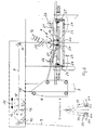
- the device shown in the drawing first includes a frame 1, which is arranged above a conveyor 2, on which stacks of material 3, only one of which is shown, are successively fed to the device.
- a separating device 4 is arranged in a stationary manner on the frame 1 and a device 5 for gathering and tensioning and pulling a stretch film hood over the stack of goods 3 guided up and down.
- This device 5 is held on a carriage 6 which can be moved up and down on a mast 7 arranged next to the frame 1.
- a carriage (not shown) belongs to the carriage 6.
- a film tube 9 is first pulled off essentially vertically upwards and then horizontally via a deflection roller 10 to a deflection roller 11, which is located above a take-off device with a motor 12 and associated take-off rollers 13.
- the take-off rollers 13 are located above the separating device 4.
- guide rails 14 for a carriage 15 guided thereon are laid in the transport direction of the film tube 9.
- the carriage has an actuator (not shown) and can be moved back and forth in the direction of the double arrow 16.
- An upper, fixed welding jaw 17 and a lower, movable welding jaw 18 are arranged on the carriage 15.
- the lower welding jaw 18 has a drive, not shown, with which it can be moved against the upper welding jaw 17.
- the film tube 9 extends between the two welding jaws 17, 18.
- the carriage 15 is moved into such a position that the length of the film tube 9 between the welding jaws 17, 18 and the separating device 4 corresponds to the length of the stretch film hood to be cut by the film tube 9.
- the parts of the tensioning frame 23 are then moved towards one another so that the edge sections of the film tube held by the grippers 20 are pulled over the outside of the tensioning frame 22.
- the stenter and its slide 6 can be slightly lowered.
- gathering rollers 25 are fed against the outer sides of the tenter frame 23.
- the gathering rollers 25 are driven and pull the film material over the outside of the tenter frame 23, the film material being gathered in the longitudinal direction.
- the parts of the tenter frame 23 are then moved apart and the stretch film hood is stretched in the circumferential direction. At the same time, the top of the stretch film hood is stretched with the cooled head weld.
- the device 5 is then lowered over the stack of goods 3, the stretch film hood pulling away from the device 5 and laying tightly around the stack of goods 3.
- the head weld seam for the next stretch film hood is already attached to the film tube.
- a height measuring device (not shown) can be arranged in the feed area of the stacks of goods 3, which measures the height of the following stack of goods to be packaged, the required hood length being determined from the measured value and then the carriage 15 is adjusted with the welding jaws 17, 18.
Description
Die Erfindung betrifft eine Vorrichtung zum Verpacken eines Gutstapels mit einer Stretchfolienhaube, mit Führungen für einen Folienschlauch, einer Schweißeinrichtung für die Kopfschweißnaht, einer Trenneinrichtung zum Abschneiden der Stretchfolienhaube vom Folienschlauch, einer Einrichtung zum Raffen, Spannen und Ziehen der Stretchfolienhaube über den Gutstapel, wobei die Schweißeinrichtung im Abstand einer Haubenlänge und in Transportrichtung des Folienschlauches vor der Trenneinrichtung angeordnet ist.The invention relates to a device for packaging a stack of goods with a stretch film hood, with guides for a film tube, a welding device for the head weld, a separating device for cutting the stretch film hood from the film tube, a device for gathering, tensioning and pulling the stretch film hood over the stack of goods, the Welding device is arranged at a distance of a hood length and in the transport direction of the film tube in front of the separating device.
In der Praxis erfolgt das Verpacken eines Gutstapels mit einer Stretchfolienhaube ähnlich wie das Verpacken eines Gutstapels mit einer Schrumpffolienhaube, mit der Maßgabe, daß die Stretchfolienhaube sich mit Eigenspannung um den Gutstapel legt und deshalb nicht geschrumpft zu werden braucht. Zur Herstellung der Haube wird von einem Folienschlauchnehmer ein Abschnitt abgezogen und mit einer Trennschweißung vom Folienschlauch abgeschnitten, wobei gleichzeitig die Kopfschweißnaht gewendet wir. Die so gebildete Haube wird dann geöffnet und in der beschriebenen Weise über den Gutstapel gezogen. Beim Verpacken mit Stretchfolienhauben erfolgt die Trennschweißung mit gleichzeitiger Bildung der Kopfschweißnaht in der Regel am Ende des Raffvorganges und unmittelbar bevor die Stretchfolienhaube in Haubenquerrichtung gespannt wird. Sofern durch den Spannvorgang auch die Kopfschweißnaht besonders belastet wird, ist es erforderlich, die Kopfschweißnaht zunächst abkühlen zu lassen, bevor der Spannvorgang einsetzt. Das mindert die Leistung beim Verpacken von Gutstapeln.In practice, packing a stack of goods with a stretch film hood is similar to packing a stack of goods with a shrink film hood, with the proviso that the stretch film hood wraps itself around the stack of goods with its own tension and therefore does not need to be shrunk. To manufacture the hood, a section is pulled off a film tube holder and cut off from the film tube with a separating weld, at the same time turning the head weld seam. The hood thus formed is then opened and pulled over the stack of goods in the manner described. When packaging with stretch film hoods, the separation welding with simultaneous formation of the head weld seam is usually carried out at the end of the gathering process and immediately before the stretch film hood is stretched in the cross direction of the hood. If the head welding seam is also particularly stressed by the tensioning process, it is necessary to allow the head welding seam to cool down before the tensioning process begins. This reduces the performance when packing stacks of goods.
Das kann vermieden werden mit einer Vorrichtung der eingangs beschriebenen Gattung (EP-A-01 84 485), bei der die Schweißeinrichtung fest an einem Maschinengestell im Abstand einer Haubenlänge vor der Trenneinrichtung angeordnet ist und bei der zwischen der Schweißeinrichtung und der Trenneinrichtung eine Tänzerrollenanordnung vorgesehen ist, mit der die jeweils benötigte Haubenlänge einstellbar ist. Beim Wechsel einer Haubenlänge ergeben sich allerdings Betriebsunterbrechungen aufgrund der notwendigen Einstellarbeiten.This can be avoided with a device of the type described in the introduction (EP-A-01 84 485), in which the welding device is fixedly arranged on a machine frame at a distance of a hood length in front of the separating device and in which a dancer roller arrangement is provided between the welding device and the separating device with which the required hood length can be adjusted. When changing a hood length, however, there are operational interruptions due to the necessary adjustment work.
Aufgabe der Erfindung ist es, das Verpacken von Gutstapel in Stretchfolienhauben zu beschleunigen.The object of the invention is to accelerate the packing of stacks of goods in stretch film hoods.
Diese Aufgabe wird dadurch gelöst, daß die Schweißeinrichtung in Längsrichtung des Folienschlauches verstellbar ist und einen Stelltrieb aufweist, der von einer im Zuführbereich des jeweils folgenden Gutstapels angeordneten Höhenmeßeinrichtung steuerbar ist. Dabei wird die Höhe des jeweils folgenden Gutstapels gemessen und daraus die erforderliche Haubenlänge bestimmt, so daß die Kopfschweißnaht in einem diese Haubenlänge entsprechenden Abstand von dem freien Ende des Folienschlauches gelegt werden kann.This object is achieved in that the welding device is adjustable in the longitudinal direction of the film tube and has an actuating drive which can be controlled by a height measuring device arranged in the feed area of the following stack of goods. The height of the following stack of material is measured and the required hood length is determined from it, so that the head weld seam can be placed at a distance corresponding to this hood length from the free end of the film tube.
Bei einer bevorzugten Ausführung der Erfindung ist die Schweißeinrichtung auf einem längs des Folienschlauches verfahrbaren Wagen angeordnet. Es bietet sich an, den Wagen in einem Bereich horizontaler Führung des Folienschlauches anzuordnen. Auf dem Wagen sind eine feste und eine bewegliche Schweißbacke angeordnet und der Folienschlauch erstreckt sich zwischen den beiden Schweißbacken.In a preferred embodiment of the invention, the welding device is arranged on a carriage which can be moved along the film tube. It is advisable to arrange the carriage in an area of horizontal guidance of the film tube. A fixed and a movable sealing jaw are arranged on the carriage and the film tube extends between the two sealing jaws.
Im folgenden wird ein in der Zeichnung dargestelltes Ausführungsbeispiel der Erfindung erläutert; es zeigen:
- Fig. 1
- schematisch eine Seitenansicht einer Vorrichtung zum Verpacken von Gutstapeln mit Stretchfolienhauben,
- Fig. 2
- teilweise den Gegenstand nach Fig. 1 in vergrößerter Darstellung,
- Fig. 3
- den Gegenstand nach Fig. 2 in anderer Funktionsstellung.
- Fig. 1
- schematically a side view of a device for packaging stacks of goods with stretch film hoods,
- Fig. 2
- partially the object of FIG. 1 in an enlarged view,
- Fig. 3
- 2 in a different functional position.
Zu der in der Zeichnung dargestellten Vorrichtung gehört zunächst ein Gestell 1, welches über einem Förderer 2 angeordnet ist, auf dem hintereinander Gutstapel 3, von denen nur einer dargestellt ist, der Vorrichtung zugeführt werden.The device shown in the drawing first includes a
Am Gestell 1 ist eine Trenneinrichtung 4 ortsfest angeordnet und eine Einrichtung 5 zum Raffen, Spannen und Überziehen einer Stretchfolienhaube über den Gutstapel 3 auf- und niederbeweglich geführt. Diese Einrichtung 5 ist an einem Schlitten 6 gehalten, der an einem neben dem Gestell 1 angeordneten Mast 7 auf- und niederbeweglich ist. Zum Schlitten 6 gehört ein nicht dargestellter Antrieb.A separating
Von einem neben dem Mast 7 angeordneten Folienschlauchwickel 8 wird ein Folienschlauch 9 zunächst im wesentlichen vertikal nach oben abgezogen und dann über eine Umlenkrolle 10 horizontal weitergeführt bis zu einer Umlenkrolle 11, die sich oberhalb einer Abzugseinrichtung mit einem Motor 12 und zugeordneten Abzugsrollen 13 befindet. Die Abzugsrollen 13 befinden sich oberhalb der Trenneinrichtung 4.From a film tube winding 8 arranged next to the
Im Bereich des horizontalen Führungsabschnittes des Folienschlauches 9 zwischen den Umlenkrollen 10, 11 sind in Transportrichtung des Folienschlauches 9 verlaufende Führungsschienen 14 für einen darauf geführten Wagen 15 verlegt. Der Wagen besitzt einen nicht gezeichneten Stelltrieb und kann in Richtung des Doppelpfeils 16 hin- und herbewegt werden. Auf dem Wagen 15 sind eine obere, feste Schweißbacke 17 und eine untere, bewegliche Schweißbacke 18 angeordnet. Die untere Schweißbacke 18 besitzt einen nicht dargestellten Antrieb, mit dem sie gegen die obere Schweißbacke 17 bewegt werden kann. Zwischen den beiden Schweißbacken 17, 18 erstreckt sich der Folienschlauch 9.In the region of the horizontal guide section of the
Der Wagen 15 wird in eine solche Position bewegt, daß die Länge des Folienschlauches 9 zwischen den Schweißbacken 17, 18 und der Trenneinrichtung 4 der Länge der von dem Folienschlauch 9 anzuschneidenden Stretchfolienhaube entspricht.The
Während die vorangehende Stretchfolienhaube, wie weiter unten beschrieben wird, mit der Einrichtung 5 gerafft, gespannt und über den Gutstapel 3 gezogen wird, wird mit Hilfe der Schweißbacken 17, 18 am Folienschlauch 9 eine Kopfschweißnaht für die folgende Stretchfolienhaube gelegt. Diese Kopfschweißnaht kann sich abkühlen, bis die vorangehende Stretchfolienhaube auf den Gutstapel aufgezogen worden ist und der nächste Gutstapel mit dem Förderer 2 unter die Einrichtung 5 gebracht worden ist. Dann wird das freie Ende des Folienschlauches, 9, welches sich im Bereich der Trenneinrichtung 4 befindet, etwas vorgezogen, so daß über die Unterseite der Trenneinrichtung 4 vorsteht. Mit der Trenneinrichtung 4 verbundene Sauger 19 greifen beidseits am Ende des Folienschlauches 9 an und öffnen diesen, so daß die freien Ränder des Folienschlauches dann von Greifern 20 erfaßt werden können, die an den Enden von Schwenkarmen 21 angeordnet sind. Die bei 22 gelagerten Schwenkarme 21 bzw. deren Greifer 20 ziehen den geöffneten Rand des Folienschlauches über die Unterseite des mehrteiligen Spannrahmens 23, dessen Teile in Richtung der Doppelpfeile 24 aufeinander zu- bzw. voneinander wegbewegt werden können. Die Teile des Spannrahmens 23 werden dann aufeinander zubewegt, so daß die von den Greifern 20 gehaltenen Randabschnitte des Folienschlauches über die Außenseite des Spannrahmens 22 gezogen werden. Dabei kann der Spannrahmen und sein Schlitten 6 etwas abgesenkt werden. Dann werden Raffrollen 25 gegen die Außenseiten des Spannrahmens 23 zugestellt. Die Raffrollen 25 sind angetrieben und ziehen das Folienmaterial über die Außenseite des Spannrahmens 23, wobei das Folienmaterial in Längsrichtung gerafft wird.While the preceding stretch film hood, as will be described further below, is gathered, tensioned and pulled over the stack of
Wenn die inzwischen angekühlte Kopfschweißnaht in den Bereich der Trenneinrichtung 4 gelangt, wird mit einem Messer 26, welches sich im Bereich eines der Sauger 19 befindet, oberhalb der Kopfschweißnaht ein Schnitt gelegt, wodurch die Stretchfolienhaube vom Folienschlauch 9 abgetrennt ist. Das Raffen wird dann vervollständigt.When the now cooled head weld reaches the area of the
Anschließend werden die Teile des Spannrahmens 23 auseinanderbewegt und dabei wird die Stretchfolienhaube in Umfangsrichtung gespannt. Gleichzeitig wird auch die Oberseite der Stretchfolienhaube mit der abgekühlten Kopfschweißnaht gespannt. Die Einrichtung 5 wird dann über den Gutstapel 3 abgesenkt, wobei sich die Stretchfolienhaube von der Einrichtung 5 abzieht und eng um den Gutstapel 3 legt.The parts of the
Nachdem die Stretchfolienhaube vom Folienschlauch abgetrennt worden ist, wird bereits die Kopfschweißnaht für die nächste Stretchfolienhaube am Folienschlauch angebracht.After the stretch film hood has been separated from the film tube, the head weld seam for the next stretch film hood is already attached to the film tube.
Wenn die auf dem Förderer 2 herangeführten Gutstapel unterschiedliche Höhe besitzen, kann im Zuführbereich der Gutstapel 3 eine nicht dargestellte Höhenmeßeinrichtung angeordnet werden, die die Höhe des jeweils folgenden, zu verpackenden Gutstapels mißt, wobei aus dem Meßwert die erforderliche Haubenlänge bestimmt wird und danach der Wagen 15 mit den Schweißbacken 17, 18 verstellt wird.If the stacks of goods brought up on the
Claims (3)
- Apparatus for packaging a stack of goods with a stretch film hood, comprising guide means for guiding a tubular roll of film, a heat-sealing arrangement (17, 18) for producing the upper fused seam, a separating means (4) for cutting the stretch film hood from the tubular roll of film (9), a means (5) for gripping, tensioning and drawing the stretch film hood over the stack of goods (3), the heat-sealing arrangement (17, 18) being disposed in front of the separating means (4), when viewed with respect to the direction of travel of the tubular roll of film (9), at a spacing from the separating means corresponding to one hood length, characterised in that the heat-sealing arrangement (17, 18) is displaceable in the longitudinal direction of the tubular roll of film (9) and has an adjustable drive which is controllable by a height measuring means disposed in the delivery region for the respective subsequent stack of goods (3).
- Apparatus according to claim 1, characterised in that the heat-sealing arrangement (17, 18) is disposed on a carriage (15), which is displaceable longitudinally of the tubular roll of film (9).
- Apparatus according to one of claims 1 or 2, characterised in that a fixed heat-sealing jaw (17) and a displaceable heat-sealing jaw (18) are disposed on the carriage (15), and in that the tubular roll of film (9) extends between the two heat-sealing jaws (17, 18).
Applications Claiming Priority (2)
| Application Number | Priority Date | Filing Date | Title |
|---|---|---|---|
| DE9006438U | 1990-06-07 | ||
| DE9006438U DE9006438U1 (en) | 1990-06-07 | 1990-06-07 |
Publications (2)
| Publication Number | Publication Date |
|---|---|
| EP0461461A1 EP0461461A1 (en) | 1991-12-18 |
| EP0461461B1 true EP0461461B1 (en) | 1994-02-16 |
Family
ID=6854491
Family Applications (1)
| Application Number | Title | Priority Date | Filing Date |
|---|---|---|---|
| EP19910108657 Expired - Lifetime EP0461461B1 (en) | 1990-06-07 | 1991-05-28 | Device for packing a stack of objects by means of a stretchfoil hood |
Country Status (3)
| Country | Link |
|---|---|
| EP (1) | EP0461461B1 (en) |
| DE (2) | DE9006438U1 (en) |
| DK (1) | DK0461461T3 (en) |
Families Citing this family (4)
| Publication number | Priority date | Publication date | Assignee | Title |
|---|---|---|---|---|
| DE10262028A1 (en) | 2002-12-23 | 2004-07-08 | Krones Ag | Device and method for packaging containers, in particular bottle containers |
| DE10261550B4 (en) * | 2002-12-23 | 2006-07-06 | Krones Ag | Apparatus and method for packaging containers, in particular bottle containers |
| EP2336034B1 (en) * | 2009-12-21 | 2013-01-09 | MSK - Verpackungs-Systeme GmbH | Method and device for wrapping a stack of goods with a film |
| IT201700106655A1 (en) * | 2017-09-22 | 2019-03-22 | Imp A C Srl | LOCKER WITH SYSTEM TO FACILITATE THE MAINTENANCE |
Family Cites Families (4)
| Publication number | Priority date | Publication date | Assignee | Title |
|---|---|---|---|---|
| US3852937A (en) * | 1968-08-06 | 1974-12-10 | Auburn Eng Inc | Shrink-wrapping method and apparatus |
| FR2573030B1 (en) * | 1984-11-12 | 1987-09-25 | Newtec Int | METHOD AND MACHINE FOR PACKAGING A LOAD IN A SHEATH SECTION OF A FLEXIBLE MATERIAL |
| EP0344815B2 (en) * | 1988-06-03 | 1997-10-15 | Bernhard Beumer Maschinenfabrik KG | Method and device for wrapping products, in particular stacks of products, in a stretchable film cover |
| DE8807293U1 (en) * | 1988-06-04 | 1988-07-21 | "Fix" Peter Steimel Gmbh & Co Kg, 5202 Hennef, De |
-
1990
- 1990-06-07 DE DE9006438U patent/DE9006438U1/de not_active Expired - Lifetime
-
1991
- 1991-05-28 DK DK91108657T patent/DK0461461T3/en active
- 1991-05-28 EP EP19910108657 patent/EP0461461B1/en not_active Expired - Lifetime
- 1991-05-28 DE DE91108657T patent/DE59101018D1/en not_active Expired - Lifetime
Also Published As
| Publication number | Publication date |
|---|---|
| DK0461461T3 (en) | 1994-03-14 |
| DE9006438U1 (en) | 1990-09-13 |
| EP0461461A1 (en) | 1991-12-18 |
| DE59101018D1 (en) | 1994-03-24 |
Similar Documents
| Publication | Publication Date | Title |
|---|---|---|
| EP0294820B1 (en) | Packaging method and apparatus for compressed bales | |
| EP3672875B1 (en) | Packaging system and method for packaging objects | |
| DE3117531A1 (en) | METHOD AND APPARATUS FOR PACKAGING STACKS AND THE LIKE WITH A HOT SHRINK FILM | |
| DE4017452A1 (en) | METHOD AND DEVICE FOR PRODUCING, FILLING AND SEALING BAGS | |
| DE19515719C2 (en) | Device for packaging objects in tubular bags | |
| DE1278323B (en) | Device for the production of soft bags and their transfer to a bag filling and closing machine | |
| DE4015643A1 (en) | METHOD AND DEVICE FOR PACKING PRESS BALES | |
| DE3006129C2 (en) | Machine for filling and closing plastic sacks, preferably gusseted sacks or flat sacks | |
| EP0461461B1 (en) | Device for packing a stack of objects by means of a stretchfoil hood | |
| DE3713571A1 (en) | Apparatus for the filling and closing of bags open at the top | |
| DE2729964A1 (en) | METHOD AND DEVICE FOR AUTOMATICALLY WRAPPING A TRAY FILLED WITH GOODS IN A PLASTIC FILM | |
| EP1201539A1 (en) | Device for making and preferably filling and closing of thermoplastic bags | |
| DE3819854A1 (en) | Process and apparatus for the packaging of pressed bales | |
| DE3011264C2 (en) | ||
| DE1479312A1 (en) | Machine for the execution of applications and work inside a tubular, continuous work piece made of thermoplastic or the like. material | |
| EP0043517B1 (en) | Apparatus for drawing a shrinkable film hood over a stack of goods | |
| DE2909479A1 (en) | DEVICE FOR PRODUCING BAGS | |
| DE3234929C2 (en) | Device for covering a stack of goods with a hood made of heat-shrinkable plastic | |
| DE19515718A1 (en) | Appts. for film packaging of products | |
| DE10262028A1 (en) | Device and method for packaging containers, in particular bottle containers | |
| EP0534062B1 (en) | Method for making, filling and closing bags | |
| EP0006249B1 (en) | Device for pulling a tube of heat-shrinkable plastic over a stack of goods | |
| DE3113836A1 (en) | FEED DEVICE ON A DEVICE FOR LEAVING SKINS | |
| DE3600589C1 (en) | Apparatus for drawing a side-folding tube of heat-shrinkable plastic over a product stack | |
| EP0796789A1 (en) | Method and device for making packaging hoods of plastic material foil |
Legal Events
| Date | Code | Title | Description |
|---|---|---|---|
| PUAI | Public reference made under article 153(3) epc to a published international application that has entered the european phase |
Free format text: ORIGINAL CODE: 0009012 |
|
| AK | Designated contracting states |
Kind code of ref document: A1 Designated state(s): DE DK FR GB |
|
| 17P | Request for examination filed |
Effective date: 19920526 |
|
| 17Q | First examination report despatched |
Effective date: 19930212 |
|
| GRAA | (expected) grant |
Free format text: ORIGINAL CODE: 0009210 |
|
| AK | Designated contracting states |
Kind code of ref document: B1 Designated state(s): DE DK FR GB |
|
| REG | Reference to a national code |
Ref country code: DK Ref legal event code: T3 |
|
| REF | Corresponds to: |
Ref document number: 59101018 Country of ref document: DE Date of ref document: 19940324 |
|
| GBT | Gb: translation of ep patent filed (gb section 77(6)(a)/1977) |
Effective date: 19940519 |
|
| ET | Fr: translation filed | ||
| PLBE | No opposition filed within time limit |
Free format text: ORIGINAL CODE: 0009261 |
|
| STAA | Information on the status of an ep patent application or granted ep patent |
Free format text: STATUS: NO OPPOSITION FILED WITHIN TIME LIMIT |
|
| 26N | No opposition filed | ||
| REG | Reference to a national code |
Ref country code: GB Ref legal event code: IF02 |
|
| PGFP | Annual fee paid to national office [announced via postgrant information from national office to epo] |
Ref country code: FR Payment date: 20100611 Year of fee payment: 20 Ref country code: DK Payment date: 20100512 Year of fee payment: 20 |
|
| PGFP | Annual fee paid to national office [announced via postgrant information from national office to epo] |
Ref country code: DE Payment date: 20100507 Year of fee payment: 20 |
|
| PGFP | Annual fee paid to national office [announced via postgrant information from national office to epo] |
Ref country code: GB Payment date: 20100519 Year of fee payment: 20 |
|
| REG | Reference to a national code |
Ref country code: DE Ref legal event code: R071 Ref document number: 59101018 Country of ref document: DE |
|
| REG | Reference to a national code |
Ref country code: DK Ref legal event code: EUP |
|
| REG | Reference to a national code |
Ref country code: GB Ref legal event code: PE20 Expiry date: 20110527 |
|
| PG25 | Lapsed in a contracting state [announced via postgrant information from national office to epo] |
Ref country code: GB Free format text: LAPSE BECAUSE OF EXPIRATION OF PROTECTION Effective date: 20110527 |
|
| PG25 | Lapsed in a contracting state [announced via postgrant information from national office to epo] |
Ref country code: DE Free format text: LAPSE BECAUSE OF EXPIRATION OF PROTECTION Effective date: 20110529 |