EP0461176B1 - Verfahren zur mittelzuteilung in einem funksystem - Google Patents
Verfahren zur mittelzuteilung in einem funksystem Download PDFInfo
- Publication number
- EP0461176B1 EP0461176B1 EP90904468A EP90904468A EP0461176B1 EP 0461176 B1 EP0461176 B1 EP 0461176B1 EP 90904468 A EP90904468 A EP 90904468A EP 90904468 A EP90904468 A EP 90904468A EP 0461176 B1 EP0461176 B1 EP 0461176B1
- Authority
- EP
- European Patent Office
- Prior art keywords
- symbol
- matrix
- interaction
- interference
- rows
- Prior art date
- Legal status (The legal status is an assumption and is not a legal conclusion. Google has not performed a legal analysis and makes no representation as to the accuracy of the status listed.)
- Expired - Lifetime
Links
Images


Classifications
-
- H—ELECTRICITY
- H04—ELECTRIC COMMUNICATION TECHNIQUE
- H04W—WIRELESS COMMUNICATION NETWORKS
- H04W16/00—Network planning, e.g. coverage or traffic planning tools; Network deployment, e.g. resource partitioning or cells structures
- H04W16/18—Network planning tools
-
- H—ELECTRICITY
- H04—ELECTRIC COMMUNICATION TECHNIQUE
- H04W—WIRELESS COMMUNICATION NETWORKS
- H04W24/00—Supervisory, monitoring or testing arrangements
- H04W24/10—Scheduling measurement reports ; Arrangements for measurement reports
-
- H—ELECTRICITY
- H04—ELECTRIC COMMUNICATION TECHNIQUE
- H04W—WIRELESS COMMUNICATION NETWORKS
- H04W72/00—Local resource management
- H04W72/50—Allocation or scheduling criteria for wireless resources
- H04W72/54—Allocation or scheduling criteria for wireless resources based on quality criteria
- H04W72/541—Allocation or scheduling criteria for wireless resources based on quality criteria using the level of interference
-
- H—ELECTRICITY
- H04—ELECTRIC COMMUNICATION TECHNIQUE
- H04W—WIRELESS COMMUNICATION NETWORKS
- H04W72/00—Local resource management
- H04W72/50—Allocation or scheduling criteria for wireless resources
- H04W72/54—Allocation or scheduling criteria for wireless resources based on quality criteria
- H04W72/542—Allocation or scheduling criteria for wireless resources based on quality criteria using measured or perceived quality
Definitions
- Radio systems can be one-way with communication in only one direction, for example paging system, or two-way, for example mobile radio system.
- a mobile radio system is preferably dealt with, but it is understood that the invention is equally well applicable to one-way systems. It is important in a mobile radio system that accessible frequency resources are used in such a manner that the system capacity is optimized with the condition that the customers experience an acceptable quality.
- accessible frequency resources are used in such a manner that the system capacity is optimized with the condition that the customers experience an acceptable quality.
- the channel allocation can be tailored to the current traffic distribution.
- Such planning is a very demanding task and there are great gains to be made if the system operator has full control over the inherent interferences in the system. Improved quality and traffic handling in a given frequency band is also equivalent to an increased frequency economy.
- exclusion matrix produces a description in symbolic form of how different base stations, alternatively mobiles in different coverage areas, can be shared with respect to co-channel and adjacent-channel conditions. Allocating algorithms are then used for finding exactly which channels the different base stations must have for the minimum requirement for connection quality to be met.
- the exclusion matrix in turn enables an allocating program to be driven and channel allocations are obtained for a situation with very well known and desired interference characteristics which ensure a good connection quality.
- the allocating algorithm includes a random control and the number of frequencies therefore does not become the same with each iteration. If the number of frequencies in a frequency plan is less than or equal to the calculated lower limit for the frequency requirement, an acceptable frequency plan has been found and the iterations are concluded.
- a method and an apparatus for making frequency channel assignment in a radiotelephone communicationsystem is known from US-A-4 736 453.
- This document teaches a method for channel allocation in a radio system comprising a number of base stations with associated coverage areas and mobile stations, the potential interaction between transmitters, especially mobiles, in the system being defined in a matrix form and the channel allocations being performed using an allocation algorith including mathematical/logical operations on the matrix.
- This is a dynamic method in that every mobile is monitored continuously to form an interference matrix of very large size, e.g. 1,000,000 entries.
- an interference matrix of very large size, e.g. 1,000,000 entries.
- the present invention offers a new and improved allocating algorithm which on the one hand utilizes figures of merit calculated in a mathematical/logical way for forming possible combinations of stations and on the other hand utilizes a random technique for the selection of one of these combinations.
- the invention is specified in greater detail in the subsequent patent claims.
- the prerequisites are that there are a number of base stations each with its own coverage area and a frequency band for the system with a limited number of channels.
- the field strengths are measured along the relevant routes in the respective coverage areas. From the measured values the cross-interference matrices are calculated which indicate the interference characteristic between transmitters by means of numeric values. From the cross-interference matrices is calculated an exclusion matrix which indicates in symbolic form the interference characteristics between transmitters, and especially base stations.
- the channel allocation is carried.out with the aid of the exclusion matrix.
- the received power from all base stations is measured on the relevant traffic routes in the geographic area which is covered by the mobile radio system.
- the measured field strengths provide mean values over sections of 20 m (approximately 30 wavelengths) and each section is tied to a coordinate designation.
- the field strength values are represented in the measured material of the received signal power in dBm.
- the measurements are not as comprehensive as they could be since, in the same process, field strengths can be registered for up to 12 base stations at a time. It is quite possible to make all necessary measurements for a cell including coverage and interference range in one night. This type of measurement has already been successfully performed in the Swiss area.
- the measurements provide knowledge about what potential power a receiver in a mobile set will receive from different cells whilst the mobile is located in the geographic area. It is also easy to calculate the potentially received power at an arbitrary base station originating from mobile stations within the coverage area. Consequently the interference situation both for mobile stations and base stations is known.
- exclusion matrix provides a systematic description in symbolic form of how different base stations or alternatively mobile stations in different coverage areas can be shared with respect to co-channel and adjacent-channel conditions.
- the appearance of the matrix is based on which limit values are set for interference and coverage. It is important to understand that an exclusion matrix certainly contains information on how the channels can be arranged, but in spite of this is not a quantity which is based on frequency but only describes the relations between field strengths in the space.
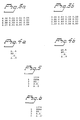
- FIG. 1 The downlinking situation is shown in Figure 1. Assuming that all the base stations together with the corresponding service areas are numbered from 1 to N. Figure 1 shows two stations i and j with the associated service areas. A mobile station M in the i-th coverage area receives a desired power Pi from its own base station and an unwanted interference power Pj from base station number j. There is a small difference between the term "service area” and "coverage area”. Coverage area here means all measured paths which, with respect to a given base station, have a sufficiently high received power to allow satisfactory reception. In the service area there can be points which have not been measured to have good reception.
- the minimum allowable C/I (carrier to interference) noise ratio for acceptable co-channel quality is LP1 and the minimum allowable C/I for acceptable quality for interference in the first adjacent channel is LP2 and so forth.
- C/I carrier to interference
- LP1 the minimum allowable C/I for acceptable quality for interference in the first adjacent channel
- LP2 the minimum allowable C/I for acceptable quality for interference in the first adjacent channel
- This cross-interference matrix P refers to the downlinking situation and describes which degree of interference the mobile stations are subject to with respect to the transmitting base stations.
- Figure 2 illustrates the uplinking situation.
- the figure shows two base stations i and j with associated service areas.
- the base station i is exposed to interference Qj from a mobile station Mj in the coverage area of base station j.
- the base station i receives a wanted power Qi from a mobile station Mi in its coverage area.
- the coverage areas are defined in the same way as before or possibly adjusted for any imbalance in the power budgets for uplinking and downlinking.
- an interference power is generated in the base station i.
- the interference power at the base station i which falls below y% of the coverage area in j is designated by Qjy. Suitable values of y can be 50 or 90.
- the minimum allowable C/I noise ratio for an acceptable co-channel quality is designated by LQ1 and the minimum C/I for an acceptable quality for the first adjacent channel is designated by LQ2 and so forth.
- C/I must be greater than LQk, k ⁇ M in the same way as before.
- the noise figure q is defined as the fraction of the coverage area of base i for which it holds true that Qi/Qjy ⁇ LQk
- This cross-interference matrix Q relates to the uplinking situation and describes which degree of interference the receivers in the base stations are subject to with respect to transmitting mobile stations.
- the uplinking matrix can be calculated in the following way.
- a noise power is generated in base i.
- the noise power varies with the instantaneous position of the interfering mobile station and its different noise power results can be characterized statistically by means of a distribution function.
- the power values Q in the base stations from the transmitting mobile stations are directly relateable to the power values P from the transmitting base stations due to the fact that the transmission losses between base and mobile station do not depend on the transmitting direction. Since the P-value is only obtained by measuring wave propagation data, this also applies to Q values.
- each coverage area must be studied with respect to all the other coverage areas. This must be done for all the threshold values corresponding to co-channel interference or adjacent-channel interference. It implies that all elements in all relevant cross-interference matrices must be calculated. Whilst processing measurement data, it is generally unavoidable to calculate all elements in the downlinking and uplinking matrices for the cross-interferences with respect to at least the co-channel case and the case of noise in the first adjacent channel, that is to say two cross-interference matrices must be calculated for downlinking and two for uplinking.
- exclusion matrix In the matrix a distinction is made between at least three different degrees of interference which are usually designated, X or A in ascending degrees of difficulty. The symbol ".” designates an interference which is negligible.
- the diagonal has elements which are usually designated by 0 and which indicate which base station the row or column in the matrix relates to, for example 0 in row number j means that all interferences relate to the coverage area of base station number j.
- the corresponding exclusion matrix can be formed in the following way:
- the matrix elements vij in the uplinking matrix are formed in corresponding manner by using the cross-interference matrices Qij (LQ2) and Qij (LQ1) and corresponding limit values for the degree of interference py.
- Figure 3a shows an example of a cross-interference matrix Pij (LP2) and Figure 3b shows a cross-interference matrix Pij (LP1). It holds true that Pij (LP2) ⁇ Pij (LP1); for the rest, there is no connection between the matrices, neither are the matrices symmetric.
- the exclusion matrix is shown in Figure 4a.
- the symbols ".”, "X” and “A” correspond to interferences of increasing degree of difficulty.
- An interference corresponding to ".” can be accepted as a co-channel interference.
- the symbol “0" indicates the coverage area to which the interferences in the same column relate.
- the matrix according to Figure 4a can be interpreted as follows. A mobile station with coverage from base station 1 cannot share a channel for reception with a mobile station in coverage areas 2 and 4. However, it can share a channel with a mobile station in coverage area 3. It cannot use an adjacent channel to a channel used by a mobile station in coverage area 4.
- a mobile station with coverage from base station 2 can share a channel for reception with a mobile station in coverage area 1.
- a mobile station in coverage area 2 is thus not exposed to interferences from base station 1 but a mobile station in coverage area 1 is exposed to interferences from base station 2.
- the exclusion matrix is therefore symmetrized by allowing matrix elements which represent the stronger degree of disturbance to be applicable. If the matrix in Figure 4a is symmetrized, the matrix in Figure 4b is obtained which in this case represents the downlinking matrix.
- FIG. 5 An example of an uplinking matrix is given in Figure 5.
- the base station 1 cannot share a channel with base stations 2, 3 and 4 nor can it have an adjacent channel to base station 4 in receiving mode.
- Base station 2 is exposed to negligible interference from mobile stations in the coverage areas of base station 3 and 4 and can therefore share a channel with these base stations, and so forth.
- the union of matrices U and V is defined.
- the union of two matrices is defined as the matrix with the union of corresponding elements in each matrix.
- the symbol for the union of two matrix elements is the symbol for the element which represents the stronger interference.
- Figure 6 shows the union of the matrices in Figures 4b and 5.
- the exclusion matrix thus combined by combining its rows is used. If a certain control is required to the effect that small, individually permissible noise contributions do not add up too much during the process of allocation, for example, a further two levels "Y" and "Z" can be introduced in the following way.
- the exclusion matrix for the uplinking situation can be formed correspondingly in certain cases.
- the allocation is carried out by combining the rows in the exclusion matrix which is thus compressed.
- a channel is allocated to each row in the matrix obtained.
- randomly controlled algorithms are used.
- a randomization is carried out for selecting the continued course of the procedure.
- the Applicant has implemented an allocation procedure specified by Hale on computer and it has been possible to make certain comparisons for mobile radio applications in Sweden. It is thought that the randomly controlled allocation procedure can provide slightly less spectrum-effective allocations on average than the allocation obtained by means of the deterministic procedure. However, this is balanced by the fact that from the great number of allocations obtained by means of the randomly controlled procedure, single allocations can be obtained which are extremely good. A number of different allocations which solve the same problem provide the operator with more information than a single allocation which solves the current problem. Furthermore, certain secondary conditions which are difficult to formulate mathematically can be satisfied by a suitable selection of the required allocation from a number of allocations.
- the invention is illustrated below by means of an example. 48 stations are placed out beforehand in the Swiss area. The necessary field strengths have been measured or calculated so that the exclusion matrix can be formed as above. To simplify the discussion, it is assumed that no channels are preallocated, that is to say the allocation is carried out without boundary conditions.
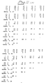
- Figure 11 is a table of a random selection of compatible rows.
- all rows in the exclusion matrix have been allocated the same figure of merit even though the number "X" differs between different rows.
- the pair of numbers in the table shows on the one hand the row number and on the other hand the figure of merit in a selection of corresponding rows.
- the very first part-table has at the top the pair of numbers representing all conceivable 48 rows and all have the same figure of merit defined as zero in this particular case. It is therefore immaterial which starting row is used and in this case row number 46 has been randomly selected. In the next part-table, all rows are shown which are compatible with row no. 46 and the figures of merit of these rows.
- figure of merit 4 in (21 4) thus represents the number of common "X" in rows 46 and 21. Among the five rows which have the highest figure of merit row 21 is randomly selected, which is thus added to row 46. In continuation, rows 32, 4, 23, 47, 41, 42, 19 and 44 are also added. These compatible rows represent the same number of base stations with associated coverage areas and all these base stations can use the same channel 1 for transmitting and receiving (channel 1 is located both in the uplinking band and the downlinking band).
- an allocating algorithm involves the purely algebraic execution of a number of row operations in a cross-interference matrix or symmetrized exclusion matrix.
- Small matrix element values in cross-interference matrices are with good approximation additive when rows are combined. This is due to the fact that the interference contributions from different transmitters in the same coverage area are independent of one another if the coverage area exposed to the interference does not constitute a significant part of the whole coverage.
- the resultant incident interference relating to the interference characteristics in different coverage areas can be sufficiently controlled during the allocation process by adding corresponding elements in the cross-interference matrices. If during this process a limit value is exceeded, this is a further restriction on the combining of rows in the exclusion matrix.
- An example of a very simple implementation of this principle is the introduction of levels "Y" and "Z" into the exclusion matrix as above.
- An interference degree B can also be included in the exclusion matrix which implies that the interference is not negligible in the second adjacent channel. Naturally, this implies a further restriction on the combining of rows.
- the symbol B will not be found in the same column in less than or equal to two rows from the symbol 0 in a current row.
- Figure 12 shows an example of the final allocating matrix. There must therefore be two rows between the symbols 0 and B in the same column, see, for example, rows 3 and 6.
- a further aid to the resource allocation is a plotting program which creates plots of the interference situation. This is because the elements in an exclusion matrix belong to one of the following three classes:
- the elements in the cross-interference matrices which relate to uncertain cell pairs must be calculated, strictly speaking. This is suitably done with the algorithms which have been specified earlier in combination with the plotting program which produces plots of downlinks and uplinks for current cell pairs.
- the Monte-Carlo methods specified in a) and b) are to be preferred.
- the plotting program calculates the degree of interference (the value of the corresponding elements in the cross-interference matrix) and provides a visual image of the interference situation which provides for extremely accurate planning of the cell and its interaction with other cells.
- the planning can now be carried out not only by taking into account the noise figure but also with respect to the total interference pattern and keeping in mind system-related aspects such as, for example, hand-over boundaries.
- the interferences do not create any problem with normal traffic loading, these interferences can be considered in these cases as belonging to the coverage area of another cell.
- the method is exacting work but provides a result of the highest quality.
- Figures 13-15 show plots of the service area of the base station in Vällingby with respect to interferences from the coverage area around the base station at Odenplan.
- the downlinking situation is illustrated in Figure 13 where the limit value for coverage is -93 dBm.
- the coverage is represented by plotted line segments, the interferences from Odenplan being designated by 0.
- the degree of interference that is to say the element in the cross-interference matrix, is calculated as 0.8%.
- Figure 14 shows a plot for a corresponding situation in the uplink. It is thus a picture of how the mobile stations in the coverage area of the base station at Odenplan interfere with the base station in Vällingby. The degree of interference is here approximately ten times higher than in the downlink.
- Figure 15 shows a plot of the uplink situation when the limit value for coverage is raised to -88 dBm.
- the coverage area has been slightly reduced but the interference situation has become acceptable with a degree of interference of approximately 4%.
- measured field strength values have been use to construct the exclusion matrix.
- the invention does not exclude the use of calculated field strength values if these are accessible.
- the invention is only limited by the patent claims below.
Landscapes
- Engineering & Computer Science (AREA)
- Computer Networks & Wireless Communication (AREA)
- Signal Processing (AREA)
- Mobile Radio Communication Systems (AREA)
- Radio Relay Systems (AREA)
Claims (9)
- Verfahren zur Kanalzuteilung in einem Mobilfunksystem, das eine Anzahl von Basisstationen mit zugehörigen Bedeckungsgebieten und Mobilstationen aufweist, wobei die potentielle Wechselwirkung zwischen Sendern in dem System definiert wird und die Basisstationen entsprechend einem Zuteilungsalgorithmus kombiniert werden, wobei die Wechselwirkung zwischen den Sendern in dem System in einer Matrix definiert wird, die durch Messen von Feldstärken von allen Basisstationen auf den relevanten Verkehrswegen in dem geographischen Gebiet des Mobilfunksystems aufgestellt wird, so daß jedes Matrixelement sich auf die Beziehung zwischen zwei Basisstationen bezieht, wobei etliche mögliche Kombinationen von Stationen durch Berechnung einer Gütezahl gebildet werden und eine dieser Kombinationen durch ein Zufallsverfahren ausgewählt wird, wobei der Zuteilungsalgorithmus mathematische/logische Operationen an der Matrix umfaßt, die dadurch reduziert wird, und wobei das Zuteilungsverfahren fortgeführt wird, bis die Matrix nicht weiter reduziert werden kann, wobei dann die reduzierte Matrix eine mögliche Kanalzuteilung darstellt.
- Verfahren nach Anspruch 1, bei dem eine Anzahl von Kanalzuteilungen ausgeführt werden, die aufgrund des Zufallsverfahren unterschiedlich sind, wobei dann die beste Zuteilung aus irgendeinem Gesichtspunkt heraus ausgewählt wird.
- Verfahren nach irgendeinem der vorhergehenden Ansprüche, bei dem die Gütezahl als Skalarprodukt zwischen Vektoren in der Matrix gebildet wird.
- Verfahren nach Anspruch 3, bei dem die Wechselwirkung in dem System durch eine Kreuzstörungsmatrix mit Elementen in der Form von numerischen Werten dargestellt wird.
- Verfahren nach Anspruch 3, bei dem die Wechselwirkung in dem System durch eine Ausschließungsmatrix mit Elementen in Zeichenform (., X, A und B) dargestellt wird.
- Verfahren nach Anspruch 3, bei dem die Wechselwirkung in dem System sowohl durch eine Ausschließungsmatrix in Zeichenform als auch eine Kreuzstörungsmatrix in numerischer Form dargestellt wird, wobei die Zeilen in der Kreuzstörungsmatrix addiert werden, wenn die zugehörigen Zeilen in der Ausschließungsmatrix kombiniert werden, wobei diese Addition eine weitere Bedingung in der genannten Kombination bildet, um den Gesamtgrad der Einfallsstörung zu kontrollieren.
- Verfahren nach Anspruch 5 oder 6, bei dem den Elementen in der Ausschließungsmatrix die folgenden Zeichen zugeordnet werden können: ein erstes Zeichen (.), das die Bedeutung hat, daß die Wechselwirkung vernachlässigbar ist in Bezug auf die Kompatibilität der Basisstation mit einer anderen Basisstation; eine zweites Zeichen (X), das die Bedeutung hat, daß die Wechselwirkung bei Belegung gleicher Kanäle nicht vernachlässigbar ist; ein drittes Zeichen (A), das die Bedeutung hat, daß die Wechselwirkung bei der Belegung benachbarter Kanäle nicht vernachlässigbar ist; und möglicherweise ein viertes Zeichen (B), das die Bedeutung hat, daß die Wechselwirkung in den zweiten benachbarten Kanälen nicht vernachlässigbar ist; und ein fünftes Zeichen (O), das anzeigt, auf welche Basisstation sich die Wechselwirkung bezieht, wobei das erste bis vierte Zeichen einen ansteigenden Grad von Wechselwirkung darstellen.
- Verfahren nach Anspruch 7, bei dem die Zeilen in der Ausschließungsmatrix potentielle Kanäle darstellen, wobei diejenigen Zeilen kombiniert werden können, die das erste Zeichen (.) oder das fünfte Zeichen (O) jeweils an entsprechenden Stellen aufweisen, während gleichzeitig Zeilen, die relativ benachbart zu der neuen, kombinierten Zeile stehen, an entsprechenden Stellen nicht das fünfte Zeichen (O) zusammen mit dem dritten Zeichen (A) aufweisen, und möglicherweise Zeilen, die relativ direkt benachbart sind, an entsprechenden Stellen gleichfalls nicht das fünfte Zeichen (O) zusammen mit dem vierten Zeichen (B) aufweisen, und wobei die Zeilen durch Bilden der Vereinigung der entsprechenden Elemente kombiniert werden, wobei das Zeichen für die Vereinigung von zwei Elementen das Zeichen für dasjenige Elemente ist, das die stärkere Wechselwirkung darstellt, und wobei die Vereinigung des ersten Zeichens (.) und des fünften Zeichens (O) als das fünfte Zeichen (O) definiert ist.
- Verfahren nach Anspruch 8, bei dem den Elementen in der Ausschließungsmatrix die folgenden weiteren Zeichen/Werte zugeordnet werden können:
ein sechstes Zeichen (Z), das einer niedrigen Wechselwirkung im gleichen Kanal entspricht;
ein siebentes Zeichen (Y), das einer geringfügig höheren Wechselwirkung im gleichen Kanal entspricht, wobei die Vereinigung von zwei Elementen mit dem sechsten Zeichen (Z) bspw. gleich dem siebenten Zeichen (Y) und die Vereinigung von zwei Elementen mit dem siebenten Zeichen (Y) bspw. gleich dem zweiten Zeichen (X) ist.
Applications Claiming Priority (3)
| Application Number | Priority Date | Filing Date | Title |
|---|---|---|---|
| SE8900742A SE465146B (sv) | 1989-03-03 | 1989-03-03 | Metod foer foerdelning av ett givet antal radiokanaler i ett radiosystem |
| SE8900742 | 1989-03-03 | ||
| PCT/SE1990/000119 WO1990010341A1 (en) | 1989-03-03 | 1990-02-22 | Method for resource allocation in a radio system |
Publications (2)
| Publication Number | Publication Date |
|---|---|
| EP0461176A1 EP0461176A1 (de) | 1991-12-18 |
| EP0461176B1 true EP0461176B1 (de) | 1995-07-12 |
Family
ID=20375223
Family Applications (1)
| Application Number | Title | Priority Date | Filing Date |
|---|---|---|---|
| EP90904468A Expired - Lifetime EP0461176B1 (de) | 1989-03-03 | 1990-02-22 | Verfahren zur mittelzuteilung in einem funksystem |
Country Status (8)
| Country | Link |
|---|---|
| US (1) | US5442804A (de) |
| EP (1) | EP0461176B1 (de) |
| AT (1) | ATE125085T1 (de) |
| CA (1) | CA2046907A1 (de) |
| DE (1) | DE69020896T2 (de) |
| ES (1) | ES2074566T3 (de) |
| SE (1) | SE465146B (de) |
| WO (1) | WO1990010341A1 (de) |
Families Citing this family (45)
| Publication number | Priority date | Publication date | Assignee | Title |
|---|---|---|---|---|
| SE465003B (sv) * | 1989-09-29 | 1991-07-08 | Televerket | Metod foer faststaellning av att parvisa celler i ett mobilradiosystem aer fullstaendigt uppmaetta |
| SE465486B (sv) * | 1989-09-29 | 1991-09-16 | Televerket | Metod foer simulering av godtycklig antenn i mobilradiosystem |
| SE8903208L (sv) * | 1989-09-29 | 1991-03-30 | Televerket | Metod foer framstaellning av taeckningsgrad i ett mobilradiosystem |
| SE465004B (sv) * | 1989-12-18 | 1991-07-08 | Televerket | Metod foer faststaellning av multipla interferenser i ett mobilradiosystem |
| US5148548A (en) * | 1989-12-19 | 1992-09-15 | Northern Telecom Limited | Method of monitoring cellular radio channels to avoid adjacent and co-channel interference |
| US5134709A (en) * | 1990-12-14 | 1992-07-28 | At&T Bell Laboratories | Process and apparatus for flexible channel assignment in cellular radiotelephone systems |
| SE9102810L (sv) * | 1991-09-27 | 1993-03-28 | Televerket | Metod att foerdela kapacitet i ett radiocellsystem |
| GB2269298A (en) * | 1992-07-28 | 1994-02-02 | Hutchison Telephone Company Li | Optimizing channel selection in cellular telephone networks |
| SE469583B (sv) * | 1992-09-01 | 1993-07-26 | Televerket | Foerfarande foer provning av oeverkoppling i mobiltelefonnaet |
| DE4302228C2 (de) * | 1993-01-27 | 1999-09-30 | Deutsche Telekom Mobil | Verfahren zur Zuweisung von Frequenzen zu Basisstationen eines Mobilfunknetzes |
| CA2176514C (en) * | 1994-10-12 | 1999-09-14 | Allan Shedlo | Method of allocating communication resources in a communication system |
| US5455821A (en) * | 1994-11-10 | 1995-10-03 | Motorola, Inc. | Communication system resource allocation method |
| DE19516063C2 (de) * | 1995-05-04 | 2000-09-21 | Deutsche Telekom Mobil | Verfahren zur Prüfung von Sendefrequenzen und zur Vergabe von Frequenzen für Basisstationen in einem zellularen Funknetz |
| BR9608410A (pt) | 1995-06-06 | 1998-12-29 | Globalstar Lp | Sistema de administração de recursos de diversidade de satélites repetidores |
| DE19525128C2 (de) * | 1995-07-12 | 1998-06-04 | Deutsche Telekom Mobil | Verfahren zur Zuweisung einer Frequenz zu einer Sende-/Empfangseinrichtung |
| US6181917B1 (en) | 1995-12-19 | 2001-01-30 | Mediaone Group, Inc. | Method and system for designing a cellular communication system |
| US5878328A (en) * | 1995-12-21 | 1999-03-02 | At&T Wireless Services, Inc. | Method and apparatus for wireless communication system organization |
| US5884147A (en) * | 1996-01-03 | 1999-03-16 | Metawave Communications Corporation | Method and apparatus for improved control over cellular systems |
| GB9603553D0 (en) * | 1996-02-20 | 1996-04-17 | Domain Dynamics Ltd | Signal processing arrangments |
| AU2581097A (en) * | 1996-03-08 | 1997-09-22 | Watkins-Johnson Company | Wireless communication system with dynamic channel allocation |
| US6496700B1 (en) | 1996-04-04 | 2002-12-17 | At&T Wireless Services, Inc. | Method for determining organization parameters in a wireless communication system |
| WO1997041706A1 (en) * | 1996-04-30 | 1997-11-06 | Motorola Inc. | Method and apparatus for automatically selecting signal radiation patterns in a wireless communication system |
| US5778317A (en) * | 1996-05-13 | 1998-07-07 | Harris Corporation | Method for allocating channels in a radio network using a genetic algorithm |
| US6041236A (en) * | 1996-12-18 | 2000-03-21 | Nortel Networks Corporation | Method and apparatus for minimizing the number of samples needed to determine cell area coverage reliability in a radiotelephone system |
| WO1999018748A1 (en) * | 1996-09-27 | 1999-04-15 | Telia Ab | Neural network application for frequency planning |
| FI107502B (fi) * | 1996-12-09 | 2001-08-15 | Nokia Networks Oy | Menetelmä taajuuden määrittämiseksi solukkoradiojärjestelmän solun käyttöön ja solukkoradiojärjestelmä |
| US6173185B1 (en) * | 1996-12-18 | 2001-01-09 | Northern Telecom Limited | Method and apparatus for minimizing the area sampled to determine cell area coverage reliability in a radiotelephone system |
| SE512077C2 (sv) * | 1997-01-22 | 2000-01-24 | Ericsson Telefon Ab L M | Förfarande och anordning för uppskattning av dämpningen i ett radiokommunikatonssystem |
| US6023622A (en) * | 1997-03-05 | 2000-02-08 | Watkins-Johnson Company | Wireless communication system with dynamic channel allocation |
| US5828961A (en) * | 1997-04-21 | 1998-10-27 | Northern Telecom Limited | System and method for partitioning a cellular environment |
| US5995840A (en) * | 1997-07-17 | 1999-11-30 | Motorola, Inc. | Method and apparatus for dynamically selecting a frequency reuse plan for a radio messaging system |
| US6173175B1 (en) * | 1997-10-21 | 2001-01-09 | Nortel Networks Limited | Process for provisioning resources in a radiotelephone network |
| DE19747834A1 (de) * | 1997-10-22 | 1999-04-29 | Mannesmann Ag | Verfahren zur Zuweisung von optimalen Betriebsparametern, insbesondere Betriebsfrequenzen |
| GB2332600B (en) * | 1997-12-19 | 2002-11-13 | Motorola Ltd | Method of providing a matrix indicating interference relationships between cells of a cellular communication system |
| US6049717A (en) * | 1998-02-02 | 2000-04-11 | Telefonaktiebolaget L M Ericsson | Operator assisted tool and method for frequency plan revision within a cellular telephone system |
| US6940838B1 (en) | 1999-08-19 | 2005-09-06 | Invertix Corporation | Wireless telephone network optimization |
| FI109953B (fi) * | 2000-02-17 | 2002-10-31 | Nokia Corp | Yhteyksien käsitteleminen matkaviestinverkossa |
| WO2001072071A1 (en) * | 2000-03-21 | 2001-09-27 | Motorola Inc. | Method of defining network cells in a communications network |
| EP1146760A3 (de) * | 2000-04-11 | 2002-05-08 | ScoreBoard, Inc. | Vorrichtung und Verfahren zur adaptiven Kanalzuweisung in einem zellularen Telefonsystem |
| US6487414B1 (en) * | 2000-08-10 | 2002-11-26 | Schema Ltd. | System and method for frequency planning in wireless communication networks |
| DE10259051A1 (de) * | 2002-12-17 | 2004-07-08 | Siemens Ag | Verfahren zur Kanalzuweisung in einem Funkkommunikationssystem |
| GB2396521A (en) * | 2002-12-18 | 2004-06-23 | Motorola Inc | Determining an interference relationship between cells of a cellular communication system |
| US9351168B2 (en) | 2010-06-29 | 2016-05-24 | Commonwealth Scientific And Industrial Research Organisation | Dynamic network configuration |
| EP3119006B1 (de) | 2015-07-15 | 2018-08-29 | RadioLED Holding AG | Verfahren und elektronik zum aufbauen eines lokalen breitbandnetzes |
| US11683823B2 (en) * | 2020-03-02 | 2023-06-20 | Fujitsu Limited | Control device and control method |
Family Cites Families (6)
| Publication number | Priority date | Publication date | Assignee | Title |
|---|---|---|---|---|
| DE3335128A1 (de) * | 1983-09-28 | 1985-04-11 | Siemens AG, 1000 Berlin und 8000 München | Mobiles funknetz |
| FR2556532B1 (fr) * | 1983-12-09 | 1986-10-24 | Trt Telecom Radio Electr | Procede de radiocommunication bidirectionnelle entre des stations fixes et des stations mobiles |
| US4736453A (en) * | 1985-12-10 | 1988-04-05 | Schloemer Gerald R | Method and apparatus for making frequency channel assignment in a cellular or non-cellular radiotelephone communications system |
| SE465486B (sv) * | 1989-09-29 | 1991-09-16 | Televerket | Metod foer simulering av godtycklig antenn i mobilradiosystem |
| SE465004B (sv) * | 1989-12-18 | 1991-07-08 | Televerket | Metod foer faststaellning av multipla interferenser i ett mobilradiosystem |
| US5038399A (en) * | 1990-05-21 | 1991-08-06 | Motorola, Inc. | Method for assigning channel reuse levels in a multi-level cellular system |
-
1989
- 1989-03-03 SE SE8900742A patent/SE465146B/sv not_active IP Right Cessation
-
1990
- 1990-02-22 AT AT90904468T patent/ATE125085T1/de not_active IP Right Cessation
- 1990-02-22 US US07/752,511 patent/US5442804A/en not_active Expired - Fee Related
- 1990-02-22 CA CA2046907A patent/CA2046907A1/en not_active Abandoned
- 1990-02-22 ES ES90904468T patent/ES2074566T3/es not_active Expired - Lifetime
- 1990-02-22 EP EP90904468A patent/EP0461176B1/de not_active Expired - Lifetime
- 1990-02-22 WO PCT/SE1990/000119 patent/WO1990010341A1/en active IP Right Grant
- 1990-02-22 DE DE69020896T patent/DE69020896T2/de not_active Expired - Fee Related
Also Published As
| Publication number | Publication date |
|---|---|
| US5442804A (en) | 1995-08-15 |
| ES2074566T3 (es) | 1995-09-16 |
| CA2046907A1 (en) | 1990-09-07 |
| SE465146B (sv) | 1991-07-29 |
| DE69020896D1 (de) | 1995-08-17 |
| WO1990010341A1 (en) | 1990-09-07 |
| EP0461176A1 (de) | 1991-12-18 |
| ATE125085T1 (de) | 1995-07-15 |
| SE8900742L (sv) | 1990-09-04 |
| SE8900742D0 (sv) | 1989-03-03 |
| DE69020896T2 (de) | 1995-11-30 |
Similar Documents
| Publication | Publication Date | Title |
|---|---|---|
| EP0461176B1 (de) | Verfahren zur mittelzuteilung in einem funksystem | |
| EP0461192B1 (de) | Plan für radiozellen | |
| US6990348B1 (en) | Self-configuring wireless system and a method to derive re-use criteria and neighboring lists therefor | |
| EP0490554B1 (de) | Verfahren und Einrichtung zur flexiblen Kanalzuweisung in Zellular-Funktelefonsystemen | |
| US6223031B1 (en) | Process and device for quality determination | |
| US6470195B1 (en) | Method and apparatus for modeling a smart antenna in a network planning tool | |
| AU702154B2 (en) | Method and apparatus for adaptive channel allocation with power control in a mobile communications system | |
| US6985735B2 (en) | Method and system for planning and evaluation of CDMA radio networks | |
| EP0458158B1 (de) | Verfahren zur Zuordnung von Kanalverteilungsmustern in einem Zellularsystem mit Wiederholungsmuster | |
| US7672672B2 (en) | Methods and techniques for penalty-based channel assignments in a cellular network | |
| US9088910B2 (en) | Method and a system for controlling the aggregate interference in cognitive radio networks | |
| EP0782360A2 (de) | System und Verfahren zur Verwaltung von Nachbarkanalinterferenz mittels zellularer Wiederholungsmuster | |
| US6137993A (en) | Method and apparatus for estimating path loss in a radio communications system | |
| CN106060946A (zh) | 一种信道分配方法及装置 | |
| EP1146760A2 (de) | Vorrichtung und Verfahren zur adaptiven Kanalzuweisung in einem zellularen Telefonsystem | |
| WO1995034957A2 (en) | Adaptive frequency allocation for broadcast control channels | |
| EP1294208A1 (de) | System und Verfahren zur Planung und Auswertung eines CDMA Funknetzes | |
| US6658256B2 (en) | Method for allocating a channel in a cell of cellular network | |
| JP5341026B2 (ja) | 無線通信方法および無線通信装置 | |
| CN102761947A (zh) | 一种基于功率控制协调同频干扰的方法和系统 | |
| Mathar et al. | An Integrated Planning Approach for Cellular Radio Networks | |
| Ho | System deployment and capacity enhancing techniques for mobile radio | |
| Furukawa et al. | Performance comparison of dynamic channel assignments for indoor microcell environment |
Legal Events
| Date | Code | Title | Description |
|---|---|---|---|
| PUAI | Public reference made under article 153(3) epc to a published international application that has entered the european phase |
Free format text: ORIGINAL CODE: 0009012 |
|
| 17P | Request for examination filed |
Effective date: 19910827 |
|
| AK | Designated contracting states |
Kind code of ref document: A1 Designated state(s): AT BE CH DE DK ES FR GB IT LI NL SE |
|
| 17Q | First examination report despatched |
Effective date: 19930823 |
|
| RAP1 | Party data changed (applicant data changed or rights of an application transferred) |
Owner name: TELIA AB |
|
| GRAA | (expected) grant |
Free format text: ORIGINAL CODE: 0009210 |
|
| AK | Designated contracting states |
Kind code of ref document: B1 Designated state(s): AT BE CH DE DK ES FR GB IT LI NL SE |
|
| PG25 | Lapsed in a contracting state [announced via postgrant information from national office to epo] |
Ref country code: DK Effective date: 19950712 Ref country code: BE Effective date: 19950712 Ref country code: AT Effective date: 19950712 |
|
| REF | Corresponds to: |
Ref document number: 125085 Country of ref document: AT Date of ref document: 19950715 Kind code of ref document: T |
|
| REF | Corresponds to: |
Ref document number: 69020896 Country of ref document: DE Date of ref document: 19950817 |
|
| ET | Fr: translation filed | ||
| ITF | It: translation for a ep patent filed |
Owner name: DATA SOLLECITO LETT. INC.:13/02/96;STUDIO MASSARI |
|
| REG | Reference to a national code |
Ref country code: ES Ref legal event code: FG2A Ref document number: 2074566 Country of ref document: ES Kind code of ref document: T3 |
|
| PG25 | Lapsed in a contracting state [announced via postgrant information from national office to epo] |
Ref country code: SE Effective date: 19951012 |
|
| PLBE | No opposition filed within time limit |
Free format text: ORIGINAL CODE: 0009261 |
|
| STAA | Information on the status of an ep patent application or granted ep patent |
Free format text: STATUS: NO OPPOSITION FILED WITHIN TIME LIMIT |
|
| 26N | No opposition filed | ||
| PGFP | Annual fee paid to national office [announced via postgrant information from national office to epo] |
Ref country code: FR Payment date: 19990120 Year of fee payment: 10 |
|
| PGFP | Annual fee paid to national office [announced via postgrant information from national office to epo] |
Ref country code: CH Payment date: 19990129 Year of fee payment: 10 |
|
| PGFP | Annual fee paid to national office [announced via postgrant information from national office to epo] |
Ref country code: ES Payment date: 19990201 Year of fee payment: 10 |
|
| PGFP | Annual fee paid to national office [announced via postgrant information from national office to epo] |
Ref country code: DE Payment date: 19990421 Year of fee payment: 10 |
|
| PGFP | Annual fee paid to national office [announced via postgrant information from national office to epo] |
Ref country code: GB Payment date: 19991129 Year of fee payment: 11 |
|
| PG25 | Lapsed in a contracting state [announced via postgrant information from national office to epo] |
Ref country code: ES Free format text: LAPSE BECAUSE OF NON-PAYMENT OF DUE FEES Effective date: 20000223 |
|
| PGFP | Annual fee paid to national office [announced via postgrant information from national office to epo] |
Ref country code: NL Payment date: 20000225 Year of fee payment: 11 |
|
| PG25 | Lapsed in a contracting state [announced via postgrant information from national office to epo] |
Ref country code: LI Free format text: LAPSE BECAUSE OF NON-PAYMENT OF DUE FEES Effective date: 20000229 Ref country code: CH Free format text: LAPSE BECAUSE OF NON-PAYMENT OF DUE FEES Effective date: 20000229 |
|
| REG | Reference to a national code |
Ref country code: CH Ref legal event code: PL |
|
| PG25 | Lapsed in a contracting state [announced via postgrant information from national office to epo] |
Ref country code: FR Free format text: LAPSE BECAUSE OF NON-PAYMENT OF DUE FEES Effective date: 20001031 |
|
| PG25 | Lapsed in a contracting state [announced via postgrant information from national office to epo] |
Ref country code: DE Free format text: LAPSE BECAUSE OF NON-PAYMENT OF DUE FEES Effective date: 20001201 |
|
| REG | Reference to a national code |
Ref country code: FR Ref legal event code: ST |
|
| PG25 | Lapsed in a contracting state [announced via postgrant information from national office to epo] |
Ref country code: GB Free format text: LAPSE BECAUSE OF NON-PAYMENT OF DUE FEES Effective date: 20010222 |
|
| PG25 | Lapsed in a contracting state [announced via postgrant information from national office to epo] |
Ref country code: NL Free format text: LAPSE BECAUSE OF NON-PAYMENT OF DUE FEES Effective date: 20010901 |
|
| GBPC | Gb: european patent ceased through non-payment of renewal fee |
Effective date: 20010222 |
|
| REG | Reference to a national code |
Ref country code: ES Ref legal event code: FD2A Effective date: 20010910 |
|
| NLV4 | Nl: lapsed or anulled due to non-payment of the annual fee |
Effective date: 20010901 |
|
| PG25 | Lapsed in a contracting state [announced via postgrant information from national office to epo] |
Ref country code: IT Free format text: LAPSE BECAUSE OF NON-PAYMENT OF DUE FEES Effective date: 20050222 |