EP0461014B1 - Anlage zur Kathodenzerstäubung mit hoher Geschwindigkeit - Google Patents
Anlage zur Kathodenzerstäubung mit hoher Geschwindigkeit Download PDFInfo
- Publication number
- EP0461014B1 EP0461014B1 EP19910401433 EP91401433A EP0461014B1 EP 0461014 B1 EP0461014 B1 EP 0461014B1 EP 19910401433 EP19910401433 EP 19910401433 EP 91401433 A EP91401433 A EP 91401433A EP 0461014 B1 EP0461014 B1 EP 0461014B1
- Authority
- EP
- European Patent Office
- Prior art keywords
- target
- installation according
- cathode
- pole piece
- electrodes
- Prior art date
- Legal status (The legal status is an assumption and is not a legal conclusion. Google has not performed a legal analysis and makes no representation as to the accuracy of the status listed.)
- Expired - Lifetime
Links
- 238000004544 sputter deposition Methods 0.000 title claims description 14
- 238000009434 installation Methods 0.000 claims description 39
- 239000000758 substrate Substances 0.000 claims description 33
- 239000002245 particle Substances 0.000 claims description 12
- 239000000463 material Substances 0.000 claims description 10
- 238000001816 cooling Methods 0.000 claims description 8
- 230000004907 flux Effects 0.000 claims description 8
- 238000002347 injection Methods 0.000 claims description 7
- 239000007924 injection Substances 0.000 claims description 7
- 238000010438 heat treatment Methods 0.000 claims description 5
- 239000011248 coating agent Substances 0.000 claims description 3
- 238000000576 coating method Methods 0.000 claims description 3
- 238000006073 displacement reaction Methods 0.000 claims description 3
- 230000000737 periodic effect Effects 0.000 claims description 3
- 230000010355 oscillation Effects 0.000 claims description 2
- 239000007789 gas Substances 0.000 description 13
- 150000001875 compounds Chemical class 0.000 description 8
- 238000005507 spraying Methods 0.000 description 8
- 230000000694 effects Effects 0.000 description 7
- 150000002500 ions Chemical class 0.000 description 7
- 238000000034 method Methods 0.000 description 5
- 230000015572 biosynthetic process Effects 0.000 description 4
- 238000006243 chemical reaction Methods 0.000 description 4
- 239000007921 spray Substances 0.000 description 4
- 230000007935 neutral effect Effects 0.000 description 3
- XKRFYHLGVUSROY-UHFFFAOYSA-N Argon Chemical compound [Ar] XKRFYHLGVUSROY-UHFFFAOYSA-N 0.000 description 2
- 238000009825 accumulation Methods 0.000 description 2
- 230000002349 favourable effect Effects 0.000 description 2
- 238000002955 isolation Methods 0.000 description 2
- 239000002184 metal Substances 0.000 description 2
- 239000000126 substance Substances 0.000 description 2
- ATJFFYVFTNAWJD-UHFFFAOYSA-N Tin Chemical compound [Sn] ATJFFYVFTNAWJD-UHFFFAOYSA-N 0.000 description 1
- 239000000956 alloy Substances 0.000 description 1
- 229910045601 alloy Inorganic materials 0.000 description 1
- 229910052786 argon Inorganic materials 0.000 description 1
- 238000005137 deposition process Methods 0.000 description 1
- 238000009792 diffusion process Methods 0.000 description 1
- 230000005684 electric field Effects 0.000 description 1
- 230000005611 electricity Effects 0.000 description 1
- 230000005281 excited state Effects 0.000 description 1
- 230000017525 heat dissipation Effects 0.000 description 1
- 239000000203 mixture Substances 0.000 description 1
- 230000001737 promoting effect Effects 0.000 description 1
- 230000006798 recombination Effects 0.000 description 1
- 238000005215 recombination Methods 0.000 description 1
- 238000009987 spinning Methods 0.000 description 1
- 239000013077 target material Substances 0.000 description 1
Images


Classifications
-
- H—ELECTRICITY
- H01—ELECTRIC ELEMENTS
- H01J—ELECTRIC DISCHARGE TUBES OR DISCHARGE LAMPS
- H01J37/00—Discharge tubes with provision for introducing objects or material to be exposed to the discharge, e.g. for the purpose of examination or processing thereof
- H01J37/32—Gas-filled discharge tubes
- H01J37/32431—Constructional details of the reactor
- H01J37/32697—Electrostatic control
-
- C—CHEMISTRY; METALLURGY
- C23—COATING METALLIC MATERIAL; COATING MATERIAL WITH METALLIC MATERIAL; CHEMICAL SURFACE TREATMENT; DIFFUSION TREATMENT OF METALLIC MATERIAL; COATING BY VACUUM EVAPORATION, BY SPUTTERING, BY ION IMPLANTATION OR BY CHEMICAL VAPOUR DEPOSITION, IN GENERAL; INHIBITING CORROSION OF METALLIC MATERIAL OR INCRUSTATION IN GENERAL
- C23C—COATING METALLIC MATERIAL; COATING MATERIAL WITH METALLIC MATERIAL; SURFACE TREATMENT OF METALLIC MATERIAL BY DIFFUSION INTO THE SURFACE, BY CHEMICAL CONVERSION OR SUBSTITUTION; COATING BY VACUUM EVAPORATION, BY SPUTTERING, BY ION IMPLANTATION OR BY CHEMICAL VAPOUR DEPOSITION, IN GENERAL
- C23C14/00—Coating by vacuum evaporation, by sputtering or by ion implantation of the coating forming material
- C23C14/22—Coating by vacuum evaporation, by sputtering or by ion implantation of the coating forming material characterised by the process of coating
- C23C14/34—Sputtering
- C23C14/35—Sputtering by application of a magnetic field, e.g. magnetron sputtering
- C23C14/354—Introduction of auxiliary energy into the plasma
- C23C14/355—Introduction of auxiliary energy into the plasma using electrons, e.g. triode sputtering
-
- H—ELECTRICITY
- H01—ELECTRIC ELEMENTS
- H01J—ELECTRIC DISCHARGE TUBES OR DISCHARGE LAMPS
- H01J37/00—Discharge tubes with provision for introducing objects or material to be exposed to the discharge, e.g. for the purpose of examination or processing thereof
- H01J37/32—Gas-filled discharge tubes
- H01J37/34—Gas-filled discharge tubes operating with cathodic sputtering
- H01J37/3402—Gas-filled discharge tubes operating with cathodic sputtering using supplementary magnetic fields
- H01J37/3405—Magnetron sputtering
- H01J37/3408—Planar magnetron sputtering
-
- H—ELECTRICITY
- H01—ELECTRIC ELEMENTS
- H01J—ELECTRIC DISCHARGE TUBES OR DISCHARGE LAMPS
- H01J2237/00—Discharge tubes exposing object to beam, e.g. for analysis treatment, etching, imaging
- H01J2237/32—Processing objects by plasma generation
- H01J2237/33—Processing objects by plasma generation characterised by the type of processing
- H01J2237/332—Coating
- H01J2237/3322—Problems associated with coating
- H01J2237/3325—Problems associated with coating large area
Definitions
- the invention relates to a spraying installation comprising a magnetron effect cathode with a high spraying rate.
- Sputtering is now a proven technique for applying fixed and uniform layers of coating material to certain substrates.
- the sputtering technique which is described in particular in patent US-2 146 025, is carried out by means of a cathode connected to a source of electricity, the cathode being placed in an enclosure in a rarefied atmosphere, in the presence of a gas (for example argon).
- a gas for example argon
- a target made in the material to be sprayed, fixed on the cathode is bombarded with energetic ions produced by the meeting of molecules of gas dispersed in the vacuum enclosure and electrons accelerated by an electric field. These gaseous ions are precipitated on the target of the cathode with sufficient energy to remove particles from it.
- the substrate to be covered is placed on the path of these particles and a thin layer of the material is deposited thereon which is made of the target and which generally consists of a metal or an alloy ("metallic mode") or a chemical compound of this pulverized material formed by reaction with a reactive gas introduced for this purpose into the spray chamber ("reactive mode").
- metallic mode a metal or an alloy
- reactive mode a chemical compound of this pulverized material formed by reaction with a reactive gas introduced for this purpose into the spray chamber
- the cathode sputtering installation according to the invention can be used advantageously both for spraying in metallic mode and for spraying in reactive mode and it is moreover particularly advantageous in the latter case.
- the yield of the sputtering technique was originally very low and it was necessary to moreover work with a relatively low vacuum.
- US Pat. No. 4,166,018 describes a flat target cathode, behind which magnets are arranged so as to produce an oval track-shaped confinement zone in which the electrons are trapped, resulting in a significant increase in the collision rate. with the gaseous atoms, impacts of ions thus generated in the vicinity of the cathode and therefore of the sputtering rate.
- the desired chemical compound is formed on the target as well as on the substrate and , preferably, with the excited molecules.
- the target is in fact coated, in zones, with a thin non-conductive or weakly conductive layer formed by reaction of the target material with the residual gas.
- the accumulation of electrons, and particularly of low energy electrons, in the immediate vicinity of the cathode causes the creation of a space charge limiting the passage of the current from the discharge.
- the object of the present invention is to provide an installation with a magnetron cathode making it possible to control the distribution and the effects of the charged particles, so as to improve the energy and chemical efficiency of the deposition process.
- Another object of the invention is to improve the quality of the layer deposited on the substrate.
- Another object of the invention is to provide an installation making it possible to work with a high vacuum in the enclosure, lower than the normal working pressure of a magnetron (some 0.1 Pa), hence a greater purity of layer.
- the object of the invention is an installation for coating substrates by sputtering, comprising a vacuum spraying chamber, a conveyor system for supporting and moving the substrates through the chamber and at least one cathode consisting of a target whose outer surface is formed of a material intended to be sprayed, said target comprising at least one active part, means for connection to a source of electric current, a cooling circuit of the target, of means of connection of this cooling circuit, of magnetic confinement means comprising magnets whose zero-sequence poles are connected by pole pieces determining the active surface of the target; the device further comprises at least one pair of electrodes disposed near the surface of the substrates, parallel to the latter, said electrodes being connected in phase opposition to a voltage source at low or medium frequency and being able to generate an oscillation of the charged particles at the height of the substrates, a reactive gas injector being placed between these electrodes.
- the reactive gas injector advantageously has the shape of a ramp and comprises two lips, at least one pair of electrodes being situated on either side of these lips, the said injector and the said electrodes being arranged at proximity of the substrate, perpendicular to the direction of movement imparted by the conveyor system to the substrates.
- this low frequency voltage source is capable of producing a square wave.
- the polar pieces of opposite polarity of the cathode are of dissimilar shape or arrangement, so that they give the lines of magnetic flux crossing the air gap an asymmetrical curvature with respect to a median plane passing between said pole pieces.
- the cathode comprises a fixed target.
- At least one of the pole pieces is located towards the front relative to the active surface of the target.
- At least one of the pole pieces projects forward towards the active surface of the target and has a directed rim in essence towards the other pole piece.
- At least one of the pole pieces extends forward relative to the active surface of the target.
- the pole piece which extends forwardly relative to the active surface of the target has, at its part furthest from the target, a flange directed substantially towards the other piece polar.
- the installation is provided with cathodes whose target is of cylindrical, hollow shape, and is provided with means able to rotate it around its axis, and with internal cooling means.
- the magnetic means are advantageously arranged outside the volume of the cylindrical target.
- the installation according to the invention comprises, near and directed towards the target, a high energy electron injection member.
- This member is advantageously an electron gun placed in the vicinity of a pole piece opening almost tangentially to the target.
- the electron injection member comprises a heating filament fixed in a groove formed under a pole piece parallel to the axis thereof, the internal face of this groove being lined with a deflector polarized at the negative voltage of the spray source capable of returning the electrons emitted by the filament to the target; this heating filament is preferably supplied by an isolation transformer delivering a periodic low voltage.
- the installation according to the invention also preferably includes a polarized electrode of so as to cause the displacement of the charged particles evolving within the plasma and placed near one of the pole pieces.
- the electrode is grounded and is placed on the side of the pole piece located opposite the maximum inflection of the magnetic field force lines in the air gap.
- the electrode is grounded via an RLC circuit, which results in self-polarization of said electrode.
- Fig. 1 is a schematic sectional view along a plane perpendicular to the axis of a conventional “race-track” double cathode track.
- the target consists of two flat sheets 1 made of material to be sprayed. Magnets 2 are placed transversely to the axis 3 of the target, behind the latter; the pole pieces 4 bring the magnetic flux to the level of the rear face of each target.
- This target 1 could also be constituted by a sheet of cylindrical shape closed on itself around the magnetic means 2.
- the electrons 6 confined between these flux lines 5 "drift", that is to say move by spinning without being able to escape. These long trajectories greatly increase the probability that these electrons meet a gas atom and ionize it. However, these reactions preferentially occur near the surface of target 1, where the confinement is maximum.
- This confinement also paradoxically plays a negative role, particularly when working in reactive mode, that is to say when gas capable of reacting with the sprayed substance is introduced into the enclosure.
- the desired compound When looking for the formation of a compound on the substrate, it is advantageous for the desired compound to form on the substrate itself or in the vicinity thereof.
- the configuration of the cathode imposes and promotes a high density of electrons near the target 1 and also of thermal secondary electrons.
- a "space charge” is formed which limits the discharge current, therefore the spray rate.
- the desired compound forms as well on target 1 as on the substrate.
- the surface of target 1 is partially covered with a film, the presence of which hinders the passage of the discharge current.
- Fig. 2 is a sectional view along a plane perpendicular to the axis of the target 1 of a "belt" cathode of the type as described in patent EP-018690 fitted out for the installation according to the invention.
- Behind target 1 is mounted the magnetic circuit; it consists of magnetic means 2 (in this case magnets) to which are joined pole pieces of dissimilar section 8, 9, which gives the resulting magnetic field 10 an asymmetrical shape.
- magnetic means 2 in this case magnets
- An autopolarized or polarized electrode by an auxiliary circuit 13 is placed at the height of the larger polar piece 9.
- This electrode 13 promotes the diffusion of electrons towards the zone 12 of least confinement.
- This electrode 13, depending on the applications, can be connected to ground, directly or via an RLC circuit 14 or even be positively or negatively biased with respect thereto. Depending on the desired effect on the particles evolving within the plasma, it is also possible to inject a periodic voltage into this electrode 13.
- this injection means 15 is constituted by a heating filament 16 held in a groove 17 formed along one of the pole pieces 9.
- a deflector 18 repels the electrons emitted in the direction of the confinement zone.
- the filament 16 is supplied through an isolation transformer (not shown).
- An auxiliary cooling circuit 19 is provided in the pole piece 9.
- the operating pressure range of the installation can be extended to pressures below one micron.
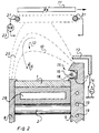
- FIG. 4 Another embodiment of this electron injection will be shown in FIG. 4. Once the electrons 6 have crossed the volume-envelope of the confined trajectories 20, they are found at proximity of the substrate 11, in place useful for causing the ionization of the flow of neutral particles arriving from the target 1 and of the atoms or molecules of reactive gas. This has the effect of promoting, at the level of the substrate 11, the formation by recombination or collision of excited very reactive neutral particles.
- This effect is amplified in the installation according to the invention by two electrodes 21 placed just above the substrate 11.
- Electrodes 21 are shown in section in FIG. 2, but they actually have the form of profiles extending over the entire width of the substrate 11.
- Electrodes 21 coupled and supplied in phase opposition are connected to a low frequency voltage source 23, preferably emitting square waves.
- the particles 6 present in the plasma are alternately attracted, then repelled by each electrode 21.
- the probability of collision between the particles is therefore greatly increased in the immediate vicinity of the substrate.
- the energy level of the thermalised electrons is raised, the molecules present are ionized and fall back to very reactive excited states favoring the formation of the desired compounds on the substrate 11, hence an improvement in the composition, the homogeneity of the deposit and of the spraying yield.
- Fig. 3 is a schematic sectional view along a plane perpendicular to the median plane of a track of a planar target which can be used in the installation, with injection of electrons 6 at high energy level by an electron gun 22.
- the electron gun 22 is oriented at a predetermined angle relative to the target 1 or tangentially to it.
- an orifice 24 is formed through the pole piece 9.
- Fig. 4 is a sectional view along a plane perpendicular to the axis of a "race-track" cathode designed for the installation according to the invention.
- the target 1 is constituted by two longitudinal strips 25 connected at their ends to form a continuous track.
- the magnets 2 are attached to the rear face of this track, the magnetic poles being oriented homopolar inward and outward of the curvature; the central pole pieces 26 are of substantially reduced cross section relative to the outer pole pieces 27, which causes a distortion of the configuration of the magnetic flux lines 10, favorable to the desired semi-confinement effect.
- the cathode is cooled by the presence of cooling conduits 28, as in the other models illustrated.
- Fig. 5 is a schematic sectional view along a plane perpendicular to its axis of a rotary target cathode designed for the installation according to the invention and whose magnetic circuit 29 is external.
- the target consists of a cylindrical structure 30 lined on its outer surface with material to be sprayed.
- the magnetic confinement circuit 31 is arranged externally relative to the volume of the target 1; it includes magnets 2 and pole pieces 26, 27 of unequal section, one being of small dimensions and the other of larger dimensions.
- the magnetic flux lines 10 extend between these pole pieces 26, 27 substantially parallel to the surface of the target 30. These magnetic flux lines 10 however have a curvature strongly marked towards the substrate 11 on the side of the pole piece of smaller section 26.
- the evacuation towards the substrate of electrons of relatively low energy level further promotes the heat dissipation already extremely favorable with a cathode shape as described here .
- the magnetic circuit placed outside leaves the entire volume of the target available for the cooling system.
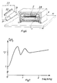
- Fig. 6 shows, in perspective, a particularly advantageous arrangement of the recollection electrodes 31.
- the substrate 11 runs horizontally under a cathode which is here seen in section.
- a ramp-shaped reactive gas injector 32 is disposed on the side of the cathode, parallel to it and close to the substrate 11. Electrodes 31 in the form of bars are fixed on either side of the lips of the injector 32 and therefore constitute a compulsory passage for these molecules of reactive gas.
- This particular configuration allows a gain of more than 10% on the sputtering rate of the cathode. This gain is a function of the material to be deposited, the voltage of the signal applied to the electrodes and its frequency. The voltage can vary, depending on the material, between 10 and 200 volts and the frequency between 100 Hz and 10 MHz.
- Fig. 7 gives, by way of example, the curve of increase in the sputtering rate (T2 / T1) as a function of the frequency of the applied signal, obtained with a tin target and under a voltage of 10 volts peak to peak.
Landscapes
- Chemical & Material Sciences (AREA)
- Engineering & Computer Science (AREA)
- Physics & Mathematics (AREA)
- Plasma & Fusion (AREA)
- Analytical Chemistry (AREA)
- Materials Engineering (AREA)
- Chemical Kinetics & Catalysis (AREA)
- Mechanical Engineering (AREA)
- Metallurgy (AREA)
- Organic Chemistry (AREA)
- Physical Vapour Deposition (AREA)
- Surface Treatment Of Glass (AREA)
- Coating By Spraying Or Casting (AREA)
Claims (18)
- Vorrichtung zur Beschichtung von Substraten durch Kathodenzerstäubung, die eine Vakuumzerstäubungskammer, ein Transportsystem für das Tragen und Bewegen der Substrate durch diese Kammer und wenigstens eine Kathode umfaßt, die aus- einem Target (1), dessen Außenfläche aus einem zu zerstäubenden Stoff besteht und das wenigstens einen aktiven Bereich enthält,- Mitteln zum Anschluß an eine elektrische Stromquelle,- einem Kühlkreislauf und Mitteln zum Anschluß an diesen Kühlkreislauf und- magnetischen Ummantelungsmitteln besteht, die Magnete (2) enthalten, deren gleichsinnige Pole über Polschuhe (8, 9, 26, 27) verbunden sind, welche die aktive Fläche des Targets bilden,dadurch gekennzeichnet, daß in der Nähe und parallel zu der Oberfläche der Substrate (11) wenigstens ein Paar aus Elektroden (21), die gegenphasig an eine niederfrequente Spannungsquelle (23) angeschlossen und in der Lage sind, eine Schwingung von geladenen Partikeln auf der Höhe der Substrate zu bewirken, und zwischen diesen Elektroden ein Injektor für Reaktionsgas angebracht ist.
- Vorrichtung nach Anspruch 1, dadurch gekennzeichnet, daß der Injektor für Reaktionsgas rohrförmig ist und zwei Austrittsöffnungen enthält, wobei wenigstens ein Paar aus Elektroden (21) auf beiden Seiten dieser Öffnungen angebracht ist und der Injektor und die Elektroden in der Nähe des Substrats senkrecht zur Richtung der den Substraten durch das Transportsystem verliehenen Bewegung angeordnet sind.
- Vorrichtung nach Anspruch 1 oder 2, dadurch gekennzeichnet, daß die niederfrequente Spannungsquelle eine Rechteckschwingung erzeugen kann.
- Vorrichtung nach einem der vorhergehenden Ansprüche, dadurch gekennzeichnet, daß die Polschuhe des Magnetkreises mit entgegengesetzter Polarität derart verschieden geformt oder angeordnet sind, daß sie den magnetischen Flußlinien, welche den Spalt überbrücken, eine in Bezug auf eine Mittenebene, die zwischen diesen Polschuhen verläuft, asymmetrische Krümmung verleihen.
- Vorrichtung nach einem der vorhergehenden Ansprüche, dadurch gekennzeichnet, daß die Kathode (7) ein festes Target (1) enthält.
- Vorrichtung nach Anspruch 5, dadurch gekennzeichnet, daß wenigstens einer der Polschuhe in Bezug auf die aktive Fläche des Targets nach vorn gerichtet angebracht ist.
- Vorrichtung nach Anspruch 6, dadurch gekennzeichnet, daß wenigstens ein Polschuh, der in Bezug auf die aktive Fläche des Targets nach vorn übersteht, einen Rand enthält, der im wesentlichen zum anderen Polschuh gerichtet ist.
- Vorrichtung nach einem der Ansprüche 1, 2, 3 und 4, dadurch gekennzeichnet, daß das Target der Kathode die Form eines hohlen Zylinders (30) aufweist und mit Mitteln versehen ist, welche es sich um seine Achse drehen lassen können.
- Vorrichtung nach Anspruch 8, dadurch gekennzeichnet, daß die magnetischen Mittel (2, 8, 9, 26, 27) an der Außenseite des zylindrischen Targets angeordnet sind.
- Vorrichtung nach Anspruch 9, dadurch gekennzeichnet, daß wenigstens einer der Polschuhe in Bezug auf die aktive Fläche des Targets nach vorn übersteht.
- Vorrichtung nach Anspruch 10, dadurch gekennzeichnet, daß der Polschuh, der in Bezug auf die aktive Fläche des Targets nach vorn übersteht, an seinem vom Target am weitesten entfernten Bereich einen Rand enthält, der im wesentlichen zum anderen Polschuh gerichtet ist.
- Vorrichtung nach einem der vorhergehenden Ansprüche, dadurch gekennzeichnet, daß die Kathode nahe des Targets und zu ihm gerichtet ein Bauteil (15, 22) für die Zufuhr von Elektronen mit hoher Energie enthält.
- Vorrichtung nach Anspruch 12, dadurch gekennzeichnet, daß das Bauteil ein Elektronenstrahler (22) ist, in der Nähe eines Polschuhs (9) angeordnet, der praktisch tangential zum Target (1) offen ist.
- Vorrichtung nach Anspruch 12, dadurch gekennzeichnet, daß das Bauteil (15, 22) für die Zufuhr der Elektronen einen Heizdraht (16) enthält, in einer Nut (17) befestigt, die in einem Polschuh parallel zu dessen Achse angebracht ist, wobei die Innenseite dieser Nut mit einer Ablenkeinrichtung (18) ausgerüstet ist, welche mit der negativen Spannung der Zerstäuberquelle polarisiert wird und die vom Draht emittierten Elektronen zum Target (1) senden kann.
- Vorrichtung nach Anspruch 14, dadurch gekennzeichnet, daß der Heizdraht (17) von einem Isoliertransformator versorgt wird, der eine periodische Niederspannung liefert.
- Vorrichtung nach einem der vorhergehenden Ansprüche, dadurch gekennzeichnet, daß eine Elektrode (13), die derart polarisiert ist, daß sie die Bewegung der im Plasma entstehenden geladenen Partikel bewirkt, in der Nähe eines der Polschuhe (8, 9) angebracht ist.
- Vorrichtung nach Anspruch 16, dadurch gekennzeichnet, daß die Elektrode mit der Masse verbunden und an der Seite des Polschuhs angeordnet ist, der sich gegenüber der maximalen Ablenkung der Kraftlinien des Magnetfelds im Spalt befindet.
- Vorrichtung nach Anspruch 17, dadurch gekennzeichnet, daß die Elektrode über einen RLC-Stromkreis (14) mit der Masse verbunden ist.
Applications Claiming Priority (2)
| Application Number | Priority Date | Filing Date | Title |
|---|---|---|---|
| BE9000576 | 1990-06-08 | ||
| BE9000576A BE1004442A3 (fr) | 1990-06-08 | 1990-06-08 | Installation de pulverisation cathodique a taux eleve. |
Publications (2)
| Publication Number | Publication Date |
|---|---|
| EP0461014A1 EP0461014A1 (de) | 1991-12-11 |
| EP0461014B1 true EP0461014B1 (de) | 1994-08-17 |
Family
ID=3884816
Family Applications (1)
| Application Number | Title | Priority Date | Filing Date |
|---|---|---|---|
| EP19910401433 Expired - Lifetime EP0461014B1 (de) | 1990-06-08 | 1991-06-03 | Anlage zur Kathodenzerstäubung mit hoher Geschwindigkeit |
Country Status (4)
| Country | Link |
|---|---|
| EP (1) | EP0461014B1 (de) |
| BE (1) | BE1004442A3 (de) |
| DE (1) | DE69103478T2 (de) |
| ES (1) | ES2062713T3 (de) |
Families Citing this family (2)
| Publication number | Priority date | Publication date | Assignee | Title |
|---|---|---|---|---|
| US5873989A (en) * | 1997-02-06 | 1999-02-23 | Intevac, Inc. | Methods and apparatus for linear scan magnetron sputtering |
| DE19705884A1 (de) * | 1997-02-15 | 1998-08-20 | Leybold Ag | Plasma-Zündvorrichtung |
Family Cites Families (5)
| Publication number | Priority date | Publication date | Assignee | Title |
|---|---|---|---|---|
| US4155825A (en) * | 1977-05-02 | 1979-05-22 | Fournier Paul R | Integrated sputtering apparatus and method |
| EP0162842A1 (de) * | 1983-12-01 | 1985-12-04 | Shatterproof Glass Corporation | Gasverteilungsvorrichtung für eine zerstäubungskathode |
| GB2209769A (en) * | 1987-09-16 | 1989-05-24 | Ion Tech Ltd | Sputter coating |
| US4931158A (en) * | 1988-03-22 | 1990-06-05 | The Regents Of The Univ. Of Calif. | Deposition of films onto large area substrates using modified reactive magnetron sputtering |
| DE3834318A1 (de) * | 1988-10-08 | 1990-04-12 | Leybold Ag | Vorrichtung zum aufbringen dielektrischer oder metallischer werkstoffe |
-
1990
- 1990-06-08 BE BE9000576A patent/BE1004442A3/fr not_active IP Right Cessation
-
1991
- 1991-06-03 ES ES91401433T patent/ES2062713T3/es not_active Expired - Fee Related
- 1991-06-03 EP EP19910401433 patent/EP0461014B1/de not_active Expired - Lifetime
- 1991-06-03 DE DE1991603478 patent/DE69103478T2/de not_active Expired - Fee Related
Also Published As
| Publication number | Publication date |
|---|---|
| BE1004442A3 (fr) | 1992-11-24 |
| ES2062713T3 (es) | 1994-12-16 |
| DE69103478D1 (de) | 1994-09-22 |
| DE69103478T2 (de) | 1995-03-23 |
| EP0461014A1 (de) | 1991-12-11 |
Similar Documents
| Publication | Publication Date | Title |
|---|---|---|
| EP2954758B1 (de) | Plasmaquelle | |
| JP4907124B2 (ja) | スパッタ・コーティング用アノード | |
| BE1003701A3 (fr) | Cathode rotative. | |
| FR2490399A1 (fr) | Procede et appareil pour la pulverisation ou vaporisation utilisant une source d'ions amelioree | |
| EP1388159A1 (de) | Magnetspiegelplasmaquelle | |
| WO2002012591A1 (fr) | Procede et dispositif pour traiter des substrats metalliques au defile par plasma | |
| FR2772185A1 (fr) | Cathode de pulverisation cathodique ou d'evaporation par arc et appareil la comportant | |
| CA2700575A1 (fr) | Procede de traitement de surface d'au moins une piece au moyen de sources elementaires de plasma par resonance cyclotronique electronique | |
| EP0265320B1 (de) | Anlage zur Vakuum-Auflagerung durch reaktive Kathodenzerstäubung auf eine Glasplatte | |
| CA3103016C (en) | Single beam plasma source | |
| EP0461014B1 (de) | Anlage zur Kathodenzerstäubung mit hoher Geschwindigkeit | |
| US20240194464A1 (en) | Stable ground anode for thin film processing | |
| US20240191341A1 (en) | Stable ground anode aperture for thin film processing | |
| JPH07331433A (ja) | スパッタ装置 | |
| EP0780486A1 (de) | Verfahren und Vorrichtung zum Beschichten eines Substrats | |
| FR2741474A1 (fr) | Chambre de traitement sous vide, procede de pulverisation sous vide et dispositif formant magnetron pour la chambre | |
| EP0908924A1 (de) | Vorrichtung zur Kondensationserzeugung eines Schichtes auf einem Substrat | |
| EP4265072B1 (de) | Vorrichtung zur abscheidung von dünnschichten mit hilfe von mikrowellenplasma | |
| US6277250B1 (en) | Dual cathode arrangement for physical vapor deposition of materials onto a round substrate with high aspect ratio features | |
| EP1397820B1 (de) | Vorrichtung zur verstärkung einer abnormalen elektrischen entladung und system zur handhabung einer abnormalen elektrischen entladung mittels einer solchen vorrichtung | |
| FR3136104A1 (fr) | Dispositif à faisceau d’électrons pour le traitement d’une surface | |
| JP2777657B2 (ja) | プラズマ付着装置 | |
| FR2744462A1 (fr) | Procede et dispositif pour realiser un depot par pulverisation cathodique a partir d'une cible portee a haute temperature | |
| JPH0621352B2 (ja) | スパツタリング装置 | |
| FR3163079A1 (fr) | Procédé et système de traitement de surface d’un élément de fixation, utilisant un dispositif de pulvérisation magnétron impulsionnelle à haute puissance. |
Legal Events
| Date | Code | Title | Description |
|---|---|---|---|
| PUAI | Public reference made under article 153(3) epc to a published international application that has entered the european phase |
Free format text: ORIGINAL CODE: 0009012 |
|
| AK | Designated contracting states |
Kind code of ref document: A1 Designated state(s): DE ES FR GB IT LU NL SE |
|
| 17P | Request for examination filed |
Effective date: 19920111 |
|
| 17Q | First examination report despatched |
Effective date: 19930901 |
|
| GRAA | (expected) grant |
Free format text: ORIGINAL CODE: 0009210 |
|
| AK | Designated contracting states |
Kind code of ref document: B1 Designated state(s): DE ES FR GB IT LU NL SE |
|
| REF | Corresponds to: |
Ref document number: 69103478 Country of ref document: DE Date of ref document: 19940922 |
|
| ITF | It: translation for a ep patent filed | ||
| GBT | Gb: translation of ep patent filed (gb section 77(6)(a)/1977) |
Effective date: 19941017 |
|
| REG | Reference to a national code |
Ref country code: ES Ref legal event code: FG2A Ref document number: 2062713 Country of ref document: ES Kind code of ref document: T3 |
|
| EAL | Se: european patent in force in sweden |
Ref document number: 91401433.7 |
|
| PLBE | No opposition filed within time limit |
Free format text: ORIGINAL CODE: 0009261 |
|
| STAA | Information on the status of an ep patent application or granted ep patent |
Free format text: STATUS: NO OPPOSITION FILED WITHIN TIME LIMIT |
|
| 26N | No opposition filed | ||
| PGFP | Annual fee paid to national office [announced via postgrant information from national office to epo] |
Ref country code: SE Payment date: 19980525 Year of fee payment: 8 |
|
| PGFP | Annual fee paid to national office [announced via postgrant information from national office to epo] |
Ref country code: GB Payment date: 19980526 Year of fee payment: 8 |
|
| PGFP | Annual fee paid to national office [announced via postgrant information from national office to epo] |
Ref country code: LU Payment date: 19980610 Year of fee payment: 8 Ref country code: FR Payment date: 19980610 Year of fee payment: 8 |
|
| PGFP | Annual fee paid to national office [announced via postgrant information from national office to epo] |
Ref country code: ES Payment date: 19980616 Year of fee payment: 8 |
|
| PGFP | Annual fee paid to national office [announced via postgrant information from national office to epo] |
Ref country code: DE Payment date: 19980627 Year of fee payment: 8 |
|
| PGFP | Annual fee paid to national office [announced via postgrant information from national office to epo] |
Ref country code: NL Payment date: 19980630 Year of fee payment: 8 |
|
| PG25 | Lapsed in a contracting state [announced via postgrant information from national office to epo] |
Ref country code: LU Free format text: LAPSE BECAUSE OF NON-PAYMENT OF DUE FEES Effective date: 19990603 Ref country code: GB Free format text: LAPSE BECAUSE OF NON-PAYMENT OF DUE FEES Effective date: 19990603 |
|
| PG25 | Lapsed in a contracting state [announced via postgrant information from national office to epo] |
Ref country code: ES Free format text: LAPSE BECAUSE OF NON-PAYMENT OF DUE FEES Effective date: 19990604 |
|
| PG25 | Lapsed in a contracting state [announced via postgrant information from national office to epo] |
Ref country code: SE Free format text: THE PATENT HAS BEEN ANNULLED BY A DECISION OF A NATIONAL AUTHORITY Effective date: 19990629 |
|
| PG25 | Lapsed in a contracting state [announced via postgrant information from national office to epo] |
Ref country code: FR Free format text: THE PATENT HAS BEEN ANNULLED BY A DECISION OF A NATIONAL AUTHORITY Effective date: 19990630 |
|
| PG25 | Lapsed in a contracting state [announced via postgrant information from national office to epo] |
Ref country code: NL Free format text: LAPSE BECAUSE OF NON-PAYMENT OF DUE FEES Effective date: 20000101 |
|
| GBPC | Gb: european patent ceased through non-payment of renewal fee |
Effective date: 19990603 |
|
| EUG | Se: european patent has lapsed |
Ref document number: 91401433.7 |
|
| NLV4 | Nl: lapsed or anulled due to non-payment of the annual fee |
Effective date: 20000101 |
|
| PG25 | Lapsed in a contracting state [announced via postgrant information from national office to epo] |
Ref country code: DE Free format text: LAPSE BECAUSE OF NON-PAYMENT OF DUE FEES Effective date: 20000503 |
|
| REG | Reference to a national code |
Ref country code: FR Ref legal event code: ST |
|
| REG | Reference to a national code |
Ref country code: ES Ref legal event code: FD2A Effective date: 20010503 |
|
| PG25 | Lapsed in a contracting state [announced via postgrant information from national office to epo] |
Ref country code: IT Free format text: LAPSE BECAUSE OF NON-PAYMENT OF DUE FEES;WARNING: LAPSES OF ITALIAN PATENTS WITH EFFECTIVE DATE BEFORE 2007 MAY HAVE OCCURRED AT ANY TIME BEFORE 2007. THE CORRECT EFFECTIVE DATE MAY BE DIFFERENT FROM THE ONE RECORDED. Effective date: 20050603 |