EP0460503A2 - Akustischer Messfühler für Näherungswarngerät - Google Patents
Akustischer Messfühler für Näherungswarngerät Download PDFInfo
- Publication number
- EP0460503A2 EP0460503A2 EP91108688A EP91108688A EP0460503A2 EP 0460503 A2 EP0460503 A2 EP 0460503A2 EP 91108688 A EP91108688 A EP 91108688A EP 91108688 A EP91108688 A EP 91108688A EP 0460503 A2 EP0460503 A2 EP 0460503A2
- Authority
- EP
- European Patent Office
- Prior art keywords
- signal
- detector
- predetermined time
- counter
- counting
- Prior art date
- Legal status (The legal status is an assumption and is not a legal conclusion. Google has not performed a legal analysis and makes no representation as to the accuracy of the status listed.)
- Withdrawn
Links
Images


Classifications
-
- G—PHYSICS
- G08—SIGNALLING
- G08G—TRAFFIC CONTROL SYSTEMS
- G08G1/00—Traffic control systems for road vehicles
- G08G1/123—Traffic control systems for road vehicles indicating the position of vehicles, e.g. scheduled vehicles; Managing passenger vehicles circulating according to a fixed timetable, e.g. buses, trains, trams
-
- G—PHYSICS
- G01—MEASURING; TESTING
- G01V—GEOPHYSICS; GRAVITATIONAL MEASUREMENTS; DETECTING MASSES OR OBJECTS; TAGS
- G01V1/00—Seismology; Seismic or acoustic prospecting or detecting
- G01V1/001—Acoustic presence detection
-
- F—MECHANICAL ENGINEERING; LIGHTING; HEATING; WEAPONS; BLASTING
- F42—AMMUNITION; BLASTING
- F42C—AMMUNITION FUZES; ARMING OR SAFETY MEANS THEREFOR
- F42C13/00—Proximity fuzes; Fuzes for remote detonation
- F42C13/06—Proximity fuzes; Fuzes for remote detonation operated by sound waves
-
- G—PHYSICS
- G01—MEASURING; TESTING
- G01S—RADIO DIRECTION-FINDING; RADIO NAVIGATION; DETERMINING DISTANCE OR VELOCITY BY USE OF RADIO WAVES; LOCATING OR PRESENCE-DETECTING BY USE OF THE REFLECTION OR RERADIATION OF RADIO WAVES; ANALOGOUS ARRANGEMENTS USING OTHER WAVES
- G01S11/00—Systems for determining distance or velocity not using reflection or reradiation
- G01S11/14—Systems for determining distance or velocity not using reflection or reradiation using ultrasonic, sonic or infrasonic waves
Definitions
- This invention pertains to acoustic sensors. Particularly, the invention pertains to means for sensing acoustic signals produced by vehicles. More particularly, the invention pertains to devices that filter signals to determine whether the signals fall within a predetermined frequency band, to count zero crossings, and to count a predetermined number of zero crossing in a predetermined time in order to alert a system of the presence of a vehicle.
- seismic systems have been used to detect the presence of both heavy and light ground based vehicles.
- seismic detectors have some inherent problems.
- One of these problems is with wind induced seismic detections.
- the seismic alert system would give a false signal if the wind would be in the area of 10 to 30 mph.
- seismic systems are also dependent upon the energy level of the seismic signal and not the frequency of the signal.
- the second method often used to detect the presence of light and heavy vehicles has been acoustic signal processors.
- the present acoustic signal processors identified in prior art have been concerned with two things, they are either analog signal processors, or they are concerned with the energy level of the incoming signal.
- the applicant's invention utilizes an acoustic signal processor, however, the signal processing is digital and is concerned with the frequency of the incoming signal.
- This invention is a means for discriminating an acoustic signal utilizing the consistency of the signal's presence to determine whether it falls within a predetermined frequency band.
- the system comprises a means for sensing an acoustic signal, this means provides a first signal with a zero reference. This signal is provided to a first counter, a first counter counting each time the first signal crosses the zero reference. Thus, the first counter counts at a frequency equivalent to the primary signal being provided by the acoustic sensor.
- the counter attempts to count to a predetermined number, for instance 100, in a predetermined time. A pair of timers is utilized to ensure that this time period is observed.
- a first timer prevents the counter from outputting a second signal to a second counter until a predetermined time has elapsed.
- a second timer resets the first counter if the first counter does not reach the predetermined number, in this case 100, before the second timer reaches a specific time. If the first counter should reach the predetermined number after the first timer has reached its time out, but prior to the second timer reaching its time out, a second signal is transmitted to a second counter. Upon the second signal being transmitted to the second counter, the first counter is again reset. The second counter counts the number of second signals received, the second counter upon receiving a second predetermined number of second signals will alert, for instance a mine, that a vehicle is present. However, the second counter must receive the predetermined number of second signals within a predetermined time, or the second counter will also be reset.
- Figure 1 is a system diagram showing the operation of the system.
- Figure 2 is a flow chart which further clarifies the system diagram.
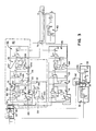
- Figure 3 is a schematic diagram of the system.
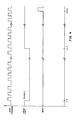
- Figure 4 is a timing diagram of the low band alert counter.
- Figure 5 is a timing diagram that demonstrates the method of zero crossing detection.
- Figure 1 is a system diagram demonstrating the means for discriminating the incoming acoustic signals for the preferred embodiment.
- the system diagram is divided up into six separate blocks each of which serves a separate function.
- the separate blocks are sensor block 10, zero crossing detector 20, rapid increasing signal detector 30, seismic alert 40, low band alert 50, and high band alert 60.
- Sensor 10 incorporates a Knowles BL 1994 microphone 11, the output of microphone 11 being input into an acoustic preamp 12 having a 60 hertz highpass filter 12. High pass filter 12 is used solely to eliminate DC offsets.
- Sensor 8 also incorporates a geophone 15 with a preamplifier 16, preamplifier 16 providing a signal to seismic alert 40. The output of acoustic preamp 12 is input into both zero crossing detector 20 and rapid increasing signal detector 30.
- Zero crossing detector 20 is a device which outputs a digital signal pulse each time the output from acoustic preamp 12 for Knowles microphone 11 crosses a zero level.
- the zero level is generally considered to be ground; however, this level may be changed at the discretion of the designer.
- the output of zero crossing detector 20 is supplied to lowband alert 50 and high band alert 60.
- Lowband alert 50 counts the number of zero crossing pulses and attempts to count to 100 within a predetermined time.
- the first block of lowband alert 50 is made up of a counter and two timers 51. Counter 51 counts the number of zero crossing pulses; upon receiving the first zero crossing pulse, both of the timers being timing. There is a lower limit timer and an upper limit timer.
- the upper limit timer blanks the output of counter 51 until a predetermined time has elapsed. In this manner if zero crossing detector 20 detects 100 zero crossings in a time that would require a higher frequency than the upper frequency limit, counter 51 would be prevented from passing on an output. If, however, the frequency of the zero crossings is low enough such that counter 51 will not count to 100 prior to this time, the first timer allows the signal to pass.
- the second timer is a low frequency timer and operates such that counter 51 is reset after a predetermined time. In this way, it prevents the system from being alerted to signals which are either of too low a frequency or are not consistent enough to have the counter count to 100 within the predetermined time. If the signal should reach a count of 100 within the time frame permitted, the signal is passed onto an "and" function 53.
- High frequency burst detector 52 looks for a series of zero detections which occur within a short period of time; for instance, four zero detections within the period of 15 milliseconds would determine that the frequency was above the desired frequency level and this would reset first counter 51.
- Rapid increasing signal detector 30 is utilized to determine whether or not there is a signal that should be rejected due to the wind or some other disturbance (e.g., gunfire or explosives).
- the output from acoustic preamp 12 is directly fed into a full wave rectifier 31.
- the rectified signal is averaged by short-term averager 32.
- the averaged signal is averaged again by a long term averager 33.
- the second average is then offset by a DC level. Both of these inputs are provided to a threshold detector and if the first average should increase at a rate dramatically higher than the second average then a wind alert is provided through "and" function block 53.
- Pulse shaper 54 is in essence a one shot which provides a signal to a second counter 55.
- Second counter 55 counts the number of signal from one shot 54 and if four signals should come within a preselected period of time, a low band alert 56 is signaled.
- the predetermined time is selected such that the signal from first counter 51 must be consistent in order to set off an alert.
- Short-term averager 32 of the rapid increasing signal detector 30 outputs a second signal to a positive voltage comparator 67.
- Positive voltage comparator 67 is in essence a threshold detector to determine whether or not the output of the short-term averager is of a sufficient level. If this signal is of a sufficient level, "anding" function block 66 allows zero crossing detector 20 signal to pass to highband alert 60.
- Highband alert 60 operates in a similar manner as lowband alert 50, the only difference being that the times are shorter in duration.
- the outputs of both lowband alert 50 and highband alert 60 are put through an "oring" function 70 in combination with seismic alert 40 and are supplied to an "anding" function 75. If either a lowband alert 50 or a highband alert 60 combined with a seismic alert 40 is present, the device will provide an alert signal.
- Figures 2A and B are a flow chart which demonstrates the functions of Figure 1.
- Figures 2A and B show the logic steps the acoustic alert takes in processing the acoustic signal for both the high band alert and the low band alert.
- Figure 3 is a schematic diagram of the preferred embodiment, the system is broken up into eighteen separate function blocks wherein function blocks 51, 52, 53, 54, 55 and 56 comprise lowband alert 50.
- Block 20 comprises the zero crossing detector
- block 66 comprises the "anding" function
- block 67 comprises the positive voltage comparator.
- Blocks 61, 62, 63, 64 and 65 comprise the remainder of highband alert 60
- block 40 comprises the seismic alert
- block 75 comprises final "anding" function
- block 70 comprises the "oring" function.
- Block 51 of lowband alert 50 comprises a 4013B dual D flip-flop 151, two 4040B 12 stage ripple carry binary counter/dividers 152 and 154 provided by National, a 4528B dual monostable multi-vibrator 153 provided by National, a 4081B quad 2 input "and" gates 155, 156, 157, and 158 provided by National and a plurality of diodes, resistors and capacitors as needed.
- Figure 4 demonstrates the timing diagram of block 51.
- Zero crossing detector 20 provides a series of pulses representative of the frequency of the acoustic signal sensed by acoustic sensors 11 (not shown in Figure 4).
- This signal is input to counter 152 which is a 4040B 12 stage ripple carry binary counter/divider.
- the signal is also input into a 4013 dual D flip-flop 151 provided by National. Dual D flip-flop 151 resets counter 152 and both timing circuits 153 and 154.
- Counter 152 begins counting the pulses from zero crossing detector 20 and attempts to count to 100.
- Upper limit counter 153 is a 4528B dual monostable multi-vibrator which upon receiving the signal from 4013 D flip-flop 151, provides a logic "0" to a fist “and” gate 157.
- the logic "0" to first "and” gate 157 prevents counter 152 from outputting a signal to blocks 53 and 54. If the time period, in this case 0.7 seconds, has elapsed, the timer then gives an enable signal or logic "1" to "and” gate 157 which allows a signal from counter 152 to pass.
- Second timer 154 is a low limit cutoff, and a 4040 counter. Second timer 154 is provided with a clock signal; the clock signal is at 1.5 kilohertz.
- Second timer 154 provides a reset to D flip-flop 151 if a period of time, in this case, 1.3 seconds has passed before counter 152 has counted to 100.
- Counter 152 upon reaching 100, provides a signal to blocks 53 and 54 and further resets D flip-flop 151.
- D flip-flop 151 may also be reset by high frequency burst detector block 52. Burst detector 52 is described below.
- a wind interrupt is connected to a 4013 dual D flip-flop 159 in block 53 which prevents one shot 251 in block 54 from providing an output block 54 is a one shot 251, one shot 251 being a 4528B which provides a pulse which is 0.6 seconds in duration. This pulse is provided to a second counter 55 which comprises a 4040 binary counter 255.
- Counter 55 has a timer 256 comprised of a 4040 counter. Timer 256 is set for 4.6 seconds and if second counter 55 does not receive four pulses from one shot 251 in block 54 in this 4.6 second period, second counter 255 will be reset along with first counter 152. If the signal is present, second counter 255 will provide a signal to a 4013 D flip-flop 257 which will provide a signal to the final pulse shaper which is block 56. D flip-flop 257 also resets counter 255 when a count of 4 is reached.
- Final pulse shaper 56 is again a one shot which provides a 3.5 second pulse. This pulse is provided to an "or" gate 70.
- High frequency burst detector 52 is made up of a pair of one shots 351 and 352 and a 4040 counter 353.
- the zero crossing signal is provided to first one shot 351.
- first one shot 351 Upon sensing a zero crossing, first one shot 351 provides a pulse with a duration of 5 milliseconds. The falling edge of the 5 milliseconds resets a counter 353.
- Counter 353 is set to count to 15 milliseconds.
- the counter 353 is a 4040 counter as described above. If one shot 351 receives a second zero crossing in less than 5 milliseconds, it will remain high until that 5 millisecond period has passed; thus, counter 353 will not be reset at the end of the first 5 millisecond pulse.
- Highband alert 60 blocks 61, 62, 63, 64 and 65 are similar to those of lowband alert 50, the only difference being that the timers are set to prevent a pass signal in less than .4 seconds and to reset the highband counter at .7 seconds.
- the analog signal directly from acoustic preamplifier 12, described in the block diagram of Figure 1, is provided to a full wave rectifier shown in block 31.
- Full wave rectifier 31 provides a rectified signal to a short-term averager 32.
- the output of short-term averager 32 is provided to a positive voltage comparator 67 and to a long-term averaging circuit 33.
- the long-term averaging circuit offsets the short-term averaging signal 32 and averages the signal a second time.
- the highband alert signal and the lowband alert signal are provided to an "or" gate 70 and if either should be present it is provided to a second "and" gate 75.
- a seismic detector 40 is also utilized. Seismic detector 40 is a simple seismic detector; this is to prevent the occurrence of low flying aircraft from triggering the system.
- Figure 5 demonstrates how an acoustic signal input into zero crossing detector 20 is output into a digital representation of the frequency.
- the output of zero crossing detector 20 switches from a logic "0" to a logic “1", or if it is currently a logic “1” will switch from a logic "1” to a logic “0".
- each and every time the primary signal from the acoustic sensor crosses the zero crossing reference and returns across the zero crossing reference a pulse is provided by zero crossing detector 20.
- the first is that an accurate digital signal is provided by zero crossing detector 20 which accurately imitates the frequency of the primary signal sensed by acoustic sensor 11.
- the second function is that high frequency noise is eliminated due to the fact that the device only switches from a logic “1” to a logic “0” or from a logic "0” to a logic “1” when the signal crosses the zero crossing reference; thus, a higher frequency may ride on the primary signal without affecting the output.
Landscapes
- Physics & Mathematics (AREA)
- Engineering & Computer Science (AREA)
- General Physics & Mathematics (AREA)
- Remote Sensing (AREA)
- Acoustics & Sound (AREA)
- Life Sciences & Earth Sciences (AREA)
- Radar, Positioning & Navigation (AREA)
- General Engineering & Computer Science (AREA)
- Environmental & Geological Engineering (AREA)
- Geology (AREA)
- General Life Sciences & Earth Sciences (AREA)
- Geophysics (AREA)
- Measurement Of Mechanical Vibrations Or Ultrasonic Waves (AREA)
- Emergency Alarm Devices (AREA)
Applications Claiming Priority (2)
| Application Number | Priority Date | Filing Date | Title |
|---|---|---|---|
| US535267 | 1990-06-08 | ||
| US07/535,267 US5007032A (en) | 1990-06-08 | 1990-06-08 | Acoustic alert sensor |
Publications (2)
| Publication Number | Publication Date |
|---|---|
| EP0460503A2 true EP0460503A2 (de) | 1991-12-11 |
| EP0460503A3 EP0460503A3 (en) | 1993-12-08 |
Family
ID=24133508
Family Applications (1)
| Application Number | Title | Priority Date | Filing Date |
|---|---|---|---|
| EP19910108688 Withdrawn EP0460503A3 (en) | 1990-06-08 | 1991-05-28 | An acoustic alert sensor |
Country Status (4)
| Country | Link |
|---|---|
| US (1) | US5007032A (de) |
| EP (1) | EP0460503A3 (de) |
| KR (1) | KR920001411A (de) |
| CA (1) | CA2041739A1 (de) |
Families Citing this family (7)
| Publication number | Priority date | Publication date | Assignee | Title |
|---|---|---|---|---|
| DE4140141C1 (de) * | 1991-12-05 | 1992-12-17 | Honeywell Regelsysteme Gmbh, 6050 Offenbach, De | |
| US5420380A (en) * | 1993-02-09 | 1995-05-30 | The United States Of America As Represented By The United States Department Of Energy | Seismic switch for strong motion measurement |
| US5339281A (en) * | 1993-08-05 | 1994-08-16 | Alliant Techsystems Inc. | Compact deployable acoustic sensor |
| KR970049929A (ko) * | 1995-12-30 | 1997-07-29 | 김광호 | 디지탈 방식을 이용한 차종 분류 방법 및 그에 따른 장치 |
| TW349717U (en) * | 1996-12-30 | 1999-01-01 | Winbond Electronics Corp | Method & apparatus for detecting surge noise in signal processor |
| US7536301B2 (en) * | 2005-01-03 | 2009-05-19 | Aai Corporation | System and method for implementing real-time adaptive threshold triggering in acoustic detection systems |
| US8036821B2 (en) * | 2007-12-18 | 2011-10-11 | Honeywell International Inc. | Methods and systems for diminishing the effects of an acoustic signature of vehicles |
Family Cites Families (17)
| Publication number | Priority date | Publication date | Assignee | Title |
|---|---|---|---|---|
| US3995223A (en) * | 1970-02-19 | 1976-11-30 | The United States Of America As Represented By The Secretary Of The Navy | Seismic-acoustic detection device |
| US3984804A (en) * | 1971-11-29 | 1976-10-05 | The United States Of America As Represented By The Secretary Of The Navy | Acoustic and seismic troop movement detector |
| US4081785A (en) * | 1974-02-13 | 1978-03-28 | The United States Of America As Represented By The Secretary Of The Air Force | Dual class amphibious target discriminator |
| US3922663A (en) * | 1974-05-30 | 1975-11-25 | Honeywell Inc | Seismic human footstep detector |
| JPS5850397B2 (ja) * | 1976-04-23 | 1983-11-10 | 三菱電機株式会社 | 異常信号等を判定する信号判定装置 |
| FR2496297A1 (fr) * | 1980-12-12 | 1982-06-18 | Thomson Csf | Dispositif de calcul de la pseudo-variance des periodes instantanees d'un signal alternatif |
| US4415979A (en) * | 1981-03-25 | 1983-11-15 | Ensco, Inc. | Method and apparatus for detecting the presence of an animate body in an inanimate mobile structure |
| US4409899A (en) * | 1981-07-27 | 1983-10-18 | The United States Of America As Represented By The Secretary Of The Air Force | Acoustic amplitude-doppler target ranging system |
| DE3204874C2 (de) * | 1982-02-11 | 1994-07-14 | Atlas Elektronik Gmbh | Passives Verfahren zum Gewinnen von Zieldaten von einer Schallquelle |
| US4604738A (en) * | 1982-02-22 | 1986-08-05 | Honeywell Inc. | Method and apparatus for classification of a moving terrestrial vehicle as light or heavy |
| DE3236000A1 (de) * | 1982-09-29 | 1984-03-29 | Blaupunkt-Werke Gmbh, 3200 Hildesheim | Verfahren zum klassifizieren von audiosignalen |
| US4468763A (en) * | 1983-05-06 | 1984-08-28 | Honeywell Inc. | Seismic intruder detection using pressure waves |
| US4530076A (en) * | 1983-06-28 | 1985-07-16 | The United States Of America As Represented By The Secretary Of The Navy | Frequency domain non-linear signal processing apparatus and method for discrimination against non-Gaussian interference |
| US4520503A (en) * | 1983-10-14 | 1985-05-28 | University Of New Mexico | Tone discrimination circuit |
| JPS61167889A (ja) * | 1985-01-18 | 1986-07-29 | Nippon Soken Inc | 距離測定装置 |
| US4653035A (en) * | 1985-07-10 | 1987-03-24 | Honeywell Inc. | Selective proximity detector |
| US4661939A (en) * | 1985-09-03 | 1987-04-28 | Honeywell Inc. | Light vehicle range discriminator |
-
1990
- 1990-06-08 US US07/535,267 patent/US5007032A/en not_active Expired - Lifetime
-
1991
- 1991-05-02 CA CA002041739A patent/CA2041739A1/en not_active Abandoned
- 1991-05-28 EP EP19910108688 patent/EP0460503A3/en not_active Withdrawn
- 1991-06-07 KR KR1019910009354A patent/KR920001411A/ko not_active Withdrawn
Also Published As
| Publication number | Publication date |
|---|---|
| US5007032A (en) | 1991-04-09 |
| EP0460503A3 (en) | 1993-12-08 |
| KR920001411A (ko) | 1992-01-30 |
| CA2041739A1 (en) | 1991-12-09 |
Similar Documents
| Publication | Publication Date | Title |
|---|---|---|
| US4612442A (en) | Passive infrared intrusion detection system | |
| US5077549A (en) | Integrating passive infrared intrusion detector | |
| US3745552A (en) | Intrusion signature detector requiring both frequency and amplitude shifts | |
| EP0053005B1 (de) | Eindringer-Warnsystem | |
| US3696369A (en) | Signal processor | |
| US5287411A (en) | System for detecting the siren of an approaching emergency vehicle | |
| US3824532A (en) | Seismic signal intrusion detection classification system | |
| US4206451A (en) | Intrusion detection system | |
| US4223304A (en) | Vibration responsive intruder alarm systems | |
| US3922663A (en) | Seismic human footstep detector | |
| US5007032A (en) | Acoustic alert sensor | |
| US3828337A (en) | Noise rejection circuitry | |
| US3717864A (en) | Periodic event detector system | |
| EP0310655B1 (de) | Kontinuierlich bereitgestellter impulszugprozessor hoher zuverlässigkeit | |
| AU616710B2 (en) | Procedure and apparatus for detecting objects moving at varying speeds within a certain area | |
| US4090180A (en) | Vibration-responsive intruder alarm system | |
| CA1295028C (en) | Electronic article surveillance system utilizing synchronous integration | |
| US4110730A (en) | Rate sensitive system for a seismic sensing range containment apparatus | |
| US3879720A (en) | Energy peak/time averaging seismic intrusion detector | |
| US5444432A (en) | Detection signal evaluation at varying signal levels | |
| US4275806A (en) | Coin sorting machine | |
| US4222046A (en) | Abnormal condition responsive means with periodic high sensitivity | |
| US4442514A (en) | Security system signal processor | |
| US3813669A (en) | Frequency filter circuit apparatus | |
| GB2221990A (en) | Vibration-sensitive intrusion detection system |
Legal Events
| Date | Code | Title | Description |
|---|---|---|---|
| PUAI | Public reference made under article 153(3) epc to a published international application that has entered the european phase |
Free format text: ORIGINAL CODE: 0009012 |
|
| AK | Designated contracting states |
Kind code of ref document: A2 Designated state(s): AT BE CH DE DK ES FR GB GR IT LI LU NL SE |
|
| RAP1 | Party data changed (applicant data changed or rights of an application transferred) |
Owner name: ALLIANT TECHSYSTEMS INC. |
|
| PUAL | Search report despatched |
Free format text: ORIGINAL CODE: 0009013 |
|
| RHK1 | Main classification (correction) |
Ipc: G01S 11/14 |
|
| AK | Designated contracting states |
Kind code of ref document: A3 Designated state(s): AT BE CH DE DK ES FR GB GR IT LI LU NL SE |
|
| 17P | Request for examination filed |
Effective date: 19940412 |
|
| STAA | Information on the status of an ep patent application or granted ep patent |
Free format text: STATUS: THE APPLICATION HAS BEEN WITHDRAWN |
|
| 18W | Application withdrawn |
Withdrawal date: 19960301 |