EP0459947A2 - Système de mesure de tension de barre dans par example machines de moulage par injection - Google Patents
Système de mesure de tension de barre dans par example machines de moulage par injection Download PDFInfo
- Publication number
- EP0459947A2 EP0459947A2 EP91810382A EP91810382A EP0459947A2 EP 0459947 A2 EP0459947 A2 EP 0459947A2 EP 91810382 A EP91810382 A EP 91810382A EP 91810382 A EP91810382 A EP 91810382A EP 0459947 A2 EP0459947 A2 EP 0459947A2
- Authority
- EP
- European Patent Office
- Prior art keywords
- force
- disk
- spar
- thin
- measuring
- Prior art date
- Legal status (The legal status is an assumption and is not a legal conclusion. Google has not performed a legal analysis and makes no representation as to the accuracy of the status listed.)
- Granted
Links
- 238000001746 injection moulding Methods 0.000 title claims abstract description 8
- 239000002184 metal Substances 0.000 claims abstract description 16
- 239000013078 crystal Substances 0.000 claims abstract description 8
- 238000000034 method Methods 0.000 claims abstract description 8
- 238000012545 processing Methods 0.000 claims abstract description 4
- 239000010453 quartz Substances 0.000 claims abstract description 3
- VYPSYNLAJGMNEJ-UHFFFAOYSA-N silicon dioxide Inorganic materials O=[Si]=O VYPSYNLAJGMNEJ-UHFFFAOYSA-N 0.000 claims abstract description 3
- 238000009434 installation Methods 0.000 claims description 4
- 238000005516 engineering process Methods 0.000 claims description 2
- 239000010409 thin film Substances 0.000 claims description 2
- 238000012544 monitoring process Methods 0.000 abstract description 5
- 238000004519 manufacturing process Methods 0.000 abstract description 3
- 238000003466 welding Methods 0.000 abstract description 3
- 239000000919 ceramic Substances 0.000 abstract 1
- 238000003908 quality control method Methods 0.000 abstract 1
- 238000005507 spraying Methods 0.000 abstract 1
- 238000002347 injection Methods 0.000 description 8
- 239000007924 injection Substances 0.000 description 8
- 238000005259 measurement Methods 0.000 description 5
- 238000010276 construction Methods 0.000 description 3
- 239000007921 spray Substances 0.000 description 3
- 238000000418 atomic force spectrum Methods 0.000 description 2
- 229920003023 plastic Polymers 0.000 description 2
- 239000004033 plastic Substances 0.000 description 2
- 239000000243 solution Substances 0.000 description 2
- 241000237858 Gastropoda Species 0.000 description 1
- 230000003321 amplification Effects 0.000 description 1
- 230000005540 biological transmission Effects 0.000 description 1
- 238000001311 chemical methods and process Methods 0.000 description 1
- 238000006243 chemical reaction Methods 0.000 description 1
- 150000001875 compounds Chemical class 0.000 description 1
- 230000006835 compression Effects 0.000 description 1
- 238000007906 compression Methods 0.000 description 1
- 238000009795 derivation Methods 0.000 description 1
- 238000009826 distribution Methods 0.000 description 1
- 230000000694 effects Effects 0.000 description 1
- 238000011156 evaluation Methods 0.000 description 1
- 230000004807 localization Effects 0.000 description 1
- 238000012423 maintenance Methods 0.000 description 1
- 238000000691 measurement method Methods 0.000 description 1
- 238000000465 moulding Methods 0.000 description 1
- 238000003199 nucleic acid amplification method Methods 0.000 description 1
- 230000000737 periodic effect Effects 0.000 description 1
- 230000003449 preventive effect Effects 0.000 description 1
- 238000007639 printing Methods 0.000 description 1
- 238000009420 retrofitting Methods 0.000 description 1
- 230000035945 sensitivity Effects 0.000 description 1
- 238000007493 shaping process Methods 0.000 description 1
- 235000012431 wafers Nutrition 0.000 description 1
Images

Classifications
-
- B—PERFORMING OPERATIONS; TRANSPORTING
- B30—PRESSES
- B30B—PRESSES IN GENERAL
- B30B15/00—Details of, or accessories for, presses; Auxiliary measures in connection with pressing
- B30B15/04—Frames; Guides
- B30B15/045—Mountings of press columns
-
- B—PERFORMING OPERATIONS; TRANSPORTING
- B29—WORKING OF PLASTICS; WORKING OF SUBSTANCES IN A PLASTIC STATE IN GENERAL
- B29C—SHAPING OR JOINING OF PLASTICS; SHAPING OF MATERIAL IN A PLASTIC STATE, NOT OTHERWISE PROVIDED FOR; AFTER-TREATMENT OF THE SHAPED PRODUCTS, e.g. REPAIRING
- B29C45/00—Injection moulding, i.e. forcing the required volume of moulding material through a nozzle into a closed mould; Apparatus therefor
- B29C45/17—Component parts, details or accessories; Auxiliary operations
- B29C45/76—Measuring, controlling or regulating
- B29C45/7653—Measuring, controlling or regulating mould clamping forces
-
- B—PERFORMING OPERATIONS; TRANSPORTING
- B30—PRESSES
- B30B—PRESSES IN GENERAL
- B30B15/00—Details of, or accessories for, presses; Auxiliary measures in connection with pressing
- B30B15/0094—Press load monitoring means
-
- G—PHYSICS
- G01—MEASURING; TESTING
- G01L—MEASURING FORCE, STRESS, TORQUE, WORK, MECHANICAL POWER, MECHANICAL EFFICIENCY, OR FLUID PRESSURE
- G01L1/00—Measuring force or stress, in general
- G01L1/16—Measuring force or stress, in general using properties of piezoelectric devices
-
- G—PHYSICS
- G01—MEASURING; TESTING
- G01L—MEASURING FORCE, STRESS, TORQUE, WORK, MECHANICAL POWER, MECHANICAL EFFICIENCY, OR FLUID PRESSURE
- G01L5/00—Apparatus for, or methods of, measuring force, work, mechanical power, or torque, specially adapted for specific purposes
-
- G—PHYSICS
- G01—MEASURING; TESTING
- G01L—MEASURING FORCE, STRESS, TORQUE, WORK, MECHANICAL POWER, MECHANICAL EFFICIENCY, OR FLUID PRESSURE
- G01L5/00—Apparatus for, or methods of, measuring force, work, mechanical power, or torque, specially adapted for specific purposes
- G01L5/0004—Force transducers adapted for mounting in a bore of the force receiving structure
Definitions
- the invention relates mainly to production machines in the plastics industry, in particular to cyclically operating injection molding machines. However, it can also be used on presses, impact shaping machines and in general on systems where variable forces have to be monitored with large screw connections. The measuring system could also be important in chemical process engineering.
- the pressure curve in the injection mold is of crucial importance for monitoring a uniform injection process in the mass production of plastic parts.
- the course of the printing process in the mold can be measured in the change in the compression of the two mold halves in the usually four bars of the machine. If you know the force curve in the spars, an overall pressure curve in the shape is automatically traceable. In many cases, this size can be used directly to control the spray screw. For complicated precision parts, where the pressure build-up has to be monitored at several points, special pressure sensors are built directly into the injection mold.
- a solution is sought that does not need to drill into the highly stressed bars.
- a thin-disk sensor is proposed for this purpose, which has a very low installation height h and is placed under the tie-bar nut in a simple manner. This means that no mechanical changes are necessary at the power transmission points of the spars, so that the invention is suitable both as new equipment and as retrofit equipment.
- strain sensors in the bore can achieve an absolute accuracy of the beam force of approx. ⁇ 3%.
- the sensor calibrated in the factory can be evaluated directly with the thin-disk sensor according to the invention, with accuracies of ⁇ 1% being possible. Recalibration in the installed state can indicate that the bars are jammed in the guide frame and must be remedied.
- the invention thus provides new possibilities for monitoring the quality of the molded parts as well as for monitoring the machine function without the need for mechanical changes to important force-conducting parts.
- the invention is therefore not only suitable for new equipment, but also particularly for retrofitting machines that are in operation.
- Fig. 1 shows schematically an injection molding machine
- 1 represents the screw head in which the molding compound is heated and pre-compressed.
- Fixed and movable parts of the machine are mounted on the machine frame 2.
- the screw head 1 ends in the injection block 3 with the spray nozzle 9.
- the tool mold 6 is mounted in the tool block 4.
- the adjustment drives are accommodated on the fixed adjustment block 5.
- Strain sensors 7 are installed in bores in each spar 14.
- Fig. 2 shows a detail of a commercially available sensor installation, prior art.
- the elongation of the spar 14 is measured with the permanently screwed-in elongation sensor 15, the elongation length 'S' of which is a multiple of the diameter d.
- the strain sensor 15 is connected to the preamplifier 10 via the cable connection 16. Plug 11 establishes the connection to the central control box.
- the flange 12 of the injection block is fastened to a shoulder part of the spar 14. Other constructions do not have this shoulder area because it has a significant notch effect.
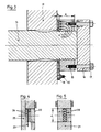
- FIG. 3 shows the solution of the spar force measurement problem according to the invention.
- 12 shows the flange section of the injection block 3.
- 19 is the thin-disc force sensor, the installation height h of which is a fraction of the nut height H. The practical height h was found to be . Due to the low height h, the thin-disc force sensor can be installed without having to change important, highly stressed parts.
- a preferred construction provides a counter flange 18 for the nut 13, which, by means of lag screws 17, ensures that the nut 13 always rests on the same thread flanks in any load condition, as a result of which the nut 13 can be prevented from loosening. This avoids dangerous force changes in the thread and the nut lock does not require any notch-processing.
- FIG. 4 shows a detail of the thin-disk force sensor 22 according to the invention from FIG. 7.
- the measuring element 22 with the piezo crystals 24 and the electrode 23 is welded to the metal disk 21 under prestress.
- the surface of the metal disk 21 is simultaneously ground with the measuring element 22 having an excess.
- FIG. 5 shows a variant of FIG. 4.
- the measuring cell 22 is arranged in a through hole '1' of the metal disk 21.
- the piezo crystal disks 24 are welded between the cover plates 26 under prestress in the metal disk 21. To Welding both surfaces are grinded vvv.
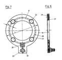
- FIG. 6 shows the thin-disk force sensor 19 according to the invention in a section with respect to FIG. 7, the construction principle according to FIG. 4 being shown again.
- the invention can be based on different variants.
- FIG. 7 shows the thin-disk force sensor 19 according to the invention in plan view.
- four measuring elements 22 are welded into the metal disk 21.
- the diameter '1' of the measuring elements 22 is related to the disk width 'B' and the overall diameter 'L'.
- the measuring elements 22 are connected in force parallel to the metal disk 21, since their surfaces are exactly flat. The measuring elements 22 thus measure only a certain part of the total force P transmitted by the spar 14. The more measuring elements 22 are arranged, the greater the measuring sensitivity. However, because the measuring elements 22 are almost as stiff as the full metal disk 21 and the forces to be measured are large, a few measuring elements 22 give a considerably larger measuring signal than is possible with strain sensors 15 according to FIG. 2.
- an amplifier 29 is installed directly in the thin-disk force sensor 19. It is connected to the individual electrodes 23 via the signal line 28. The connection line is made via connection socket 20 which is mounted in the connection part 30.
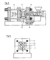
- FIG. 8 shows a possible calibration arrangement with the calibration sensor 31 of the measuring electronics 32, which is connected to the thin-disk force sensor 19.
- FIG. 9 it is indicated how the force of the individual bars as well as the total force can be measured by means of different measuring positions 0, 1, 2, 3, 4.
- 31 is the calibration sensor which is arranged between two clamping plates 33.
- the thin-disk force sensor 19 according to the invention is constructed on a piezoelectric basis because the cyclical process of the machine enables simple zeroing before each measuring stroke. Quartz disks are provided as piezo crystal disks, but in many cases piezoceramic can be more advantageous. Other sensor technologies such as strain gauges, thin film, piezoresistive or capacitive can possibly be considered for a thin-disk force sensor concept. With regard to operational safety, however, the piezoelectric arrangement, due to the simple signal derivation and the rigidity, is the suitable technique for the thin-disk force sensor according to the invention. In addition, the piezoelectric concept enables very simple impedance converters / amplifiers 29 which can be built directly into the connection part 30 in a miniature version. The connecting line from the connection socket 20 for signal processing can thus be designed as a normal cable line.
- a calibration sensor 31 is mounted between the mounting plates 33 and connected to the measuring electronics 32. If the calibration sensor 31 is centered precisely on position 0, the four spar sensors must display exactly the same values. If this is not the case, there must be internal tension and tilting or unequal span lengths, which must be corrected.
- the calibration sensor 31 can be brought into different exposure positions 1, 2, 3, 4 step by step.
- the thin-disc force sensors in connection with the calibration sensor thus allow a perfect check of the overall condition of the machine, which should be specified as preventive maintenance in the service plan of the injection molding machine.
- the spar force measuring system according to the invention with thin-disc force sensors and corresponding evaluation electronics allows the machine to be used optimally, in particular with eccentrically stressed tool shapes, and to keep the limit values under control at all times.
- the spar force measuring arrangement according to the invention thus creates a completely monitored operating sequence, which ensures uniformly high quality of the molded parts produced, but it also enables careful periodic monitoring of the entire machine system for perfect mechanical condition.
Landscapes
- Engineering & Computer Science (AREA)
- Mechanical Engineering (AREA)
- Physics & Mathematics (AREA)
- General Physics & Mathematics (AREA)
- Manufacturing & Machinery (AREA)
- Injection Moulding Of Plastics Or The Like (AREA)
- Force Measurement Appropriate To Specific Purposes (AREA)
- Moulds For Moulding Plastics Or The Like (AREA)
- Control Of Presses (AREA)
- Measuring Fluid Pressure (AREA)
Applications Claiming Priority (2)
| Application Number | Priority Date | Filing Date | Title |
|---|---|---|---|
| CH1838/90 | 1990-05-31 | ||
| CH1838/90A CH680576A5 (fr) | 1990-05-31 | 1990-05-31 |
Publications (3)
| Publication Number | Publication Date |
|---|---|
| EP0459947A2 true EP0459947A2 (fr) | 1991-12-04 |
| EP0459947A3 EP0459947A3 (en) | 1992-06-03 |
| EP0459947B1 EP0459947B1 (fr) | 1995-01-25 |
Family
ID=4219784
Family Applications (1)
| Application Number | Title | Priority Date | Filing Date |
|---|---|---|---|
| EP91810382A Expired - Lifetime EP0459947B1 (fr) | 1990-05-31 | 1991-05-21 | Système de mesure de tension de barre dans par example machines de moulage par injection |
Country Status (6)
| Country | Link |
|---|---|
| US (1) | US5154084A (fr) |
| EP (1) | EP0459947B1 (fr) |
| JP (1) | JPH04228299A (fr) |
| AT (1) | ATE117797T1 (fr) |
| CH (1) | CH680576A5 (fr) |
| DE (1) | DE59104366D1 (fr) |
Cited By (5)
| Publication number | Priority date | Publication date | Assignee | Title |
|---|---|---|---|---|
| EP0574755A1 (fr) * | 1992-06-17 | 1993-12-22 | Maschinenfabrik Müller-Weingarten AG | Dispositif pour mesurer les forces de fermeture et de serrage dans des machines de moulage par pression |
| EP0715941A3 (fr) * | 1994-12-08 | 1997-01-08 | Krauss Maffei Ag | Unité de fermeture pour une machine à mouler par injection |
| CN103448298A (zh) * | 2013-08-19 | 2013-12-18 | 无锡源创机械科技有限公司 | 一种用于双动挤压机的穿孔挤压测力保护机构 |
| CN103852203A (zh) * | 2014-02-17 | 2014-06-11 | 浙江海洋学院 | 一种超声键合压力的识别方法 |
| AT517832A4 (de) * | 2016-01-28 | 2017-05-15 | Engel Austria Gmbh | Verfahren zum Ermitteln der Lage eines Einleitungspunktes einer Auftreibkraft |
Families Citing this family (15)
| Publication number | Priority date | Publication date | Assignee | Title |
|---|---|---|---|---|
| SE9102121D0 (sv) * | 1991-07-08 | 1991-07-08 | Skf Nova Ab | Sensor system |
| DE19612018B4 (de) * | 1996-03-18 | 2005-09-29 | Dreier Technology Ag | Formmaschine |
| US6536098B1 (en) | 1998-09-14 | 2003-03-25 | Erming Luo | Method of manufacturing precisely compressed stacks |
| DE10138513B4 (de) * | 2001-08-06 | 2004-04-08 | Siemens Ag | Drehmomentsensor |
| KR100517330B1 (ko) * | 2003-03-27 | 2005-09-28 | 엘에스전선 주식회사 | 사출성형기 타이바의 위치감지장치 |
| JP4070727B2 (ja) * | 2004-01-22 | 2008-04-02 | ファナック株式会社 | 射出成形機及び射出成形機の芯だし方法 |
| WO2007102205A1 (fr) * | 2006-03-07 | 2007-09-13 | Riken Optech Corporation | système de réglage automatique de sensibilité de capteur d'instrument de mesure de charge |
| EP1693659A1 (fr) * | 2005-02-21 | 2006-08-23 | Werner Kluft | Dispositif de mesure de forces à l'intérieur d'une vis de fixation |
| TWM273444U (en) * | 2005-03-08 | 2005-08-21 | Jian-Le Li | Mold clamping force strain gauge and conversion device for detected signal thereby |
| US20080088047A1 (en) * | 2006-10-12 | 2008-04-17 | Mold-Masters Limited | Apparatus and method for a hot runner injection molding system |
| SE1050589A1 (sv) * | 2010-06-08 | 2011-11-22 | Rocan System Ab | Anordning och metod för att indikera om ett fästelement vid infästning i ett stycke har uppnått en sträckgränsbelastning |
| EP3093641B1 (fr) | 2015-05-11 | 2017-06-28 | Siemens Aktiengesellschaft | Procédé de détermination d'une force de traction axiale appliquée à un composant |
| JP6925210B2 (ja) * | 2017-09-14 | 2021-08-25 | ユニバーサル製缶株式会社 | 圧力測定センサ、圧力測定方法 |
| AT520901B1 (de) * | 2018-01-24 | 2019-11-15 | Avl List Gmbh | Messvorrichtung und Verfahren zur Bestimmung einer Kraft und/oder eines Drehmoments an einer drehmomentübertragenden Welle |
| AT521702B1 (de) * | 2019-03-11 | 2020-04-15 | Piezocryst Advanced Sensorics | Messsystem, geeignet für den einbau zwischen moment- und/oder kraftübertragenden maschinenteilen |
Family Cites Families (2)
| Publication number | Priority date | Publication date | Assignee | Title |
|---|---|---|---|---|
| US3151258A (en) * | 1960-12-10 | 1964-09-29 | Sonderegger Hans Conrad | Device for measuring the forces between components of an assembly |
| DE3666294D1 (en) * | 1986-03-18 | 1989-11-16 | Kristal Instr Ag | Piezoresistive force-measuring element and its use in determining the forces acting upon a construction |
-
1990
- 1990-05-31 CH CH1838/90A patent/CH680576A5/de not_active IP Right Cessation
-
1991
- 1991-05-21 AT AT91810382T patent/ATE117797T1/de active
- 1991-05-21 DE DE59104366T patent/DE59104366D1/de not_active Expired - Fee Related
- 1991-05-21 EP EP91810382A patent/EP0459947B1/fr not_active Expired - Lifetime
- 1991-05-31 US US07/708,375 patent/US5154084A/en not_active Expired - Fee Related
- 1991-05-31 JP JP3129717A patent/JPH04228299A/ja not_active Withdrawn
Cited By (8)
| Publication number | Priority date | Publication date | Assignee | Title |
|---|---|---|---|---|
| EP0574755A1 (fr) * | 1992-06-17 | 1993-12-22 | Maschinenfabrik Müller-Weingarten AG | Dispositif pour mesurer les forces de fermeture et de serrage dans des machines de moulage par pression |
| US5365998A (en) * | 1992-06-17 | 1994-11-22 | Maschinenfabrik Mueller-Weingarten Ag | Measuring, monitoring and regulation system for determining the locking pressure or column force and/or the casting force in pressure die casting machines |
| EP0715941A3 (fr) * | 1994-12-08 | 1997-01-08 | Krauss Maffei Ag | Unité de fermeture pour une machine à mouler par injection |
| US5736169A (en) * | 1994-12-08 | 1998-04-07 | Krauss-Maffei Ag | Closing apparatus for multiple-mold injection-molding system |
| CN103448298A (zh) * | 2013-08-19 | 2013-12-18 | 无锡源创机械科技有限公司 | 一种用于双动挤压机的穿孔挤压测力保护机构 |
| CN103852203A (zh) * | 2014-02-17 | 2014-06-11 | 浙江海洋学院 | 一种超声键合压力的识别方法 |
| AT517832A4 (de) * | 2016-01-28 | 2017-05-15 | Engel Austria Gmbh | Verfahren zum Ermitteln der Lage eines Einleitungspunktes einer Auftreibkraft |
| AT517832B1 (de) * | 2016-01-28 | 2017-05-15 | Engel Austria Gmbh | Verfahren zum Ermitteln der Lage eines Einleitungspunktes einer Auftreibkraft |
Also Published As
| Publication number | Publication date |
|---|---|
| CH680576A5 (fr) | 1992-09-30 |
| US5154084A (en) | 1992-10-13 |
| JPH04228299A (ja) | 1992-08-18 |
| DE59104366D1 (de) | 1995-03-09 |
| EP0459947A3 (en) | 1992-06-03 |
| ATE117797T1 (de) | 1995-02-15 |
| EP0459947B1 (fr) | 1995-01-25 |
Similar Documents
| Publication | Publication Date | Title |
|---|---|---|
| EP0459947B1 (fr) | Système de mesure de tension de barre dans par example machines de moulage par injection | |
| EP0042371B1 (fr) | Détecteur destiné à la mesure de déformations sur des corps creux | |
| DE2038771B2 (de) | Druck -MeBwertwandler | |
| WO2013139464A1 (fr) | Elément de jonction à capteur et procédé de fabrication | |
| EP3892974B1 (fr) | Dispositif de détection de charge, de préférence de charges de pression, de traction et / ou de torsion sur une partie de châssis de véhicule utilitaire | |
| CH682108A5 (fr) | ||
| EP1754030B1 (fr) | Securite antisurcharge pour element dynamometrique | |
| DE69226269T2 (de) | Kaliber mit gestuften blöcken | |
| DE3834090A1 (de) | Kraftsensor | |
| EP3566816B1 (fr) | Procede de vissage d'un systeme de boulons | |
| DE102017004375A1 (de) | Spritzgiessmaschine | |
| EP0190173A1 (fr) | Procede de surveillance et/ou de regulation du moulage par injection dans des presses d'injection. | |
| DE2814988B2 (de) | Vorrichtung zur Erfassung eines zwischen zwei Gegenstandes gewegbaren Maschinenteilen auftretenden, im wesentlichen axialen Kraft | |
| EP0179278A2 (fr) | Capteur de pression | |
| DE102004033925B4 (de) | Drehmoment-Messaufnehmer | |
| EP0429399A2 (fr) | Mesure de dilatation dans des structures métalliques | |
| DE4201159A1 (de) | Ventil | |
| AT394448B (de) | Vorrichtung zum messen von in eisenbahnschienen oder aehnlichen belasteten balken wirkenden kraeften | |
| DE2827061C3 (de) | Kraftmeßdose | |
| DE19826257B4 (de) | Kraftmeßgerät und Meßverfahren dazu | |
| DE102021130441A1 (de) | Messeinrichtung, System aus einem Schraubgerät und der Messeinrichtung und Verfahren zum Betreiben einer Messeinrichtung sowie Befestigungselement | |
| DE2537369A1 (de) | Dehnungsaufnehmer fuer die kraftmessung an saeulen oder zugankern von maschinen | |
| DE102023118155B3 (de) | Messsystem zur Prozess- und/oder Maschinenüberwachung | |
| DE102020129183A1 (de) | Druckmessgerät und Verfahren zur Herstellung eines Druckmessgeräts | |
| DE3119806A1 (de) | Messwertaufnehmer zur erfassung von zug- und/oder druckkraeften |
Legal Events
| Date | Code | Title | Description |
|---|---|---|---|
| PUAI | Public reference made under article 153(3) epc to a published international application that has entered the european phase |
Free format text: ORIGINAL CODE: 0009012 |
|
| AK | Designated contracting states |
Kind code of ref document: A2 Designated state(s): AT DE FR IT |
|
| PUAL | Search report despatched |
Free format text: ORIGINAL CODE: 0009013 |
|
| AK | Designated contracting states |
Kind code of ref document: A3 Designated state(s): AT DE FR IT |
|
| 17P | Request for examination filed |
Effective date: 19920511 |
|
| RAP1 | Party data changed (applicant data changed or rights of an application transferred) |
Owner name: K.K. HOLDING AG |
|
| 17Q | First examination report despatched |
Effective date: 19930716 |
|
| GRAA | (expected) grant |
Free format text: ORIGINAL CODE: 0009210 |
|
| AK | Designated contracting states |
Kind code of ref document: B1 Designated state(s): AT DE FR IT |
|
| PG25 | Lapsed in a contracting state [announced via postgrant information from national office to epo] |
Ref country code: IT Free format text: LAPSE BECAUSE OF FAILURE TO SUBMIT A TRANSLATION OF THE DESCRIPTION OR TO PAY THE FEE WITHIN THE PRE;WARNING: LAPSES OF ITALIAN PATENTS WITH EFFECTIVE DATE BEFORE 2007 MAY HAVE OCCURRED AT ANY TIME BEFORE 2007. THE CORRECT EFFECTIVE DATE MAY BE DIFFERENT FROM THE ONE RECORDED.SCRIBED TIME-LIMIT Effective date: 19950125 |
|
| REF | Corresponds to: |
Ref document number: 117797 Country of ref document: AT Date of ref document: 19950215 Kind code of ref document: T |
|
| REF | Corresponds to: |
Ref document number: 59104366 Country of ref document: DE Date of ref document: 19950309 |
|
| ET | Fr: translation filed | ||
| PLBE | No opposition filed within time limit |
Free format text: ORIGINAL CODE: 0009261 |
|
| STAA | Information on the status of an ep patent application or granted ep patent |
Free format text: STATUS: NO OPPOSITION FILED WITHIN TIME LIMIT |
|
| 26N | No opposition filed | ||
| PGFP | Annual fee paid to national office [announced via postgrant information from national office to epo] |
Ref country code: FR Payment date: 19960419 Year of fee payment: 6 |
|
| PGFP | Annual fee paid to national office [announced via postgrant information from national office to epo] |
Ref country code: AT Payment date: 19960531 Year of fee payment: 6 |
|
| PG25 | Lapsed in a contracting state [announced via postgrant information from national office to epo] |
Ref country code: AT Effective date: 19970521 |
|
| PG25 | Lapsed in a contracting state [announced via postgrant information from national office to epo] |
Ref country code: FR Free format text: LAPSE BECAUSE OF NON-PAYMENT OF DUE FEES Effective date: 19980130 |
|
| REG | Reference to a national code |
Ref country code: FR Ref legal event code: ST |
|
| PGFP | Annual fee paid to national office [announced via postgrant information from national office to epo] |
Ref country code: DE Payment date: 20030520 Year of fee payment: 13 |
|
| PG25 | Lapsed in a contracting state [announced via postgrant information from national office to epo] |
Ref country code: DE Free format text: LAPSE BECAUSE OF NON-PAYMENT OF DUE FEES Effective date: 20041201 |