EP0459653A2 - Plattenverbindungsanordnung für zerlegbare Büromöbelwandplattenraumteilersysteme - Google Patents
Plattenverbindungsanordnung für zerlegbare Büromöbelwandplattenraumteilersysteme Download PDFInfo
- Publication number
- EP0459653A2 EP0459653A2 EP91304303A EP91304303A EP0459653A2 EP 0459653 A2 EP0459653 A2 EP 0459653A2 EP 91304303 A EP91304303 A EP 91304303A EP 91304303 A EP91304303 A EP 91304303A EP 0459653 A2 EP0459653 A2 EP 0459653A2
- Authority
- EP
- European Patent Office
- Prior art keywords
- panel
- side frame
- frame member
- shoulders
- elongate member
- Prior art date
- Legal status (The legal status is an assumption and is not a legal conclusion. Google has not performed a legal analysis and makes no representation as to the accuracy of the status listed.)
- Withdrawn
Links
Images

Classifications
-
- E—FIXED CONSTRUCTIONS
- E04—BUILDING
- E04B—GENERAL BUILDING CONSTRUCTIONS; WALLS, e.g. PARTITIONS; ROOFS; FLOORS; CEILINGS; INSULATION OR OTHER PROTECTION OF BUILDINGS
- E04B2/00—Walls, e.g. partitions, for buildings; Wall construction with regard to insulation; Connections specially adapted to walls
- E04B2/74—Removable non-load-bearing partitions; Partitions with a free upper edge
- E04B2/7407—Removable non-load-bearing partitions; Partitions with a free upper edge assembled using frames with infill panels or coverings only; made-up of panels and a support structure incorporating posts
- E04B2/7416—Removable non-load-bearing partitions; Partitions with a free upper edge assembled using frames with infill panels or coverings only; made-up of panels and a support structure incorporating posts with free upper edge, e.g. for use as office space dividers
- E04B2/7422—Removable non-load-bearing partitions; Partitions with a free upper edge assembled using frames with infill panels or coverings only; made-up of panels and a support structure incorporating posts with free upper edge, e.g. for use as office space dividers with separate framed panels without intermediary support posts
- E04B2/7425—Details of connection of panels
Definitions
- This invention is concerned with office furniture demountable wall panel space divider systems, and more particularly, to the provision of a panel connecting arrangement for same, whereby the panels employed for this purpose are secured together panel to panel fashion, with a panel or the panels of such a system that are free standing in an upright mounted position in some conventional manner being employed to so secure thereto similar unattached panels as needed to complete the work station being formed.
- a familiar form of panel employed for this purpose is generally quadrilateral in shape (usually rectangular) and is composed of the usual core (which may be of one of the various types known to this art) to either side of which may be suitably secured a skin that may be of metal or plastic, with the panel core suitably mounting the usual top, bottom and side frame piece members that are of generally channel shape.
- a familiar type of side frame member commonly employed for this purpose is in the form of a channel member that includes a web extending longitudinally thereof and indented toward the panel core, with the web being disposed between a pair of coplanar shoulders at the side edges of the frame member that may be formed with a row of elongate apertures that are conventionally adapted to receive conventional hooks for cantilevering a work station component from either side of the panel of which the side frame member is a part, after the formation of the work station as such is completed.
- the preferred embodiment of the invention of the present application provides an arrangement for securing or anchoring to a freestanding panel of this type an unsecured or fresh such panel to extend and/or complete a wall for work stations or the like, with such panels being secured together in abutting relation along their adjacently disposed side frame pieces by clamping action that acts longitudinally of the side frame members of adjacent panels, and with the freestanding nature of the mounted panel being passed on to the added panel, while providing a panel subdividing system that may be readily disassembled, moved, and reassembled as needs change, and while eliminating the need for the post or standard between coplanar of such panels that has heretofore been required between the coplanar panels so secured.
- the preferred embodiment of the invention provides an arrangement for releasably securing panels of this type of divider system together for permanent use of the work station, for enlargement of same, or for ready disassembly and reassembly of same at another location using the same panels and securing arrangement therefor.
- the preferred embodiment provides an arrangement for securing together at their adjacent margins panels of the type referred to, to extend and/or form a planar panel wall, and to use only at panel wall corners, or at the juncture of panel subdivider systems of, for instance, the familiar "X", "T”, or ninety degree type, configurations, an appropriately shaped post in association with such panel securing arrangement.
- the panel connector arrangement comprises a clamp device having a pair of relatively movable, opposed and similar but reversed shaped heads that in use are respectively positioned relative to the tops of the panel side frame members involved, and indexing apertures provided in the upper portions of the side frame members involved (of the panels being secured together), with the objective of securing the freestanding panel to the unattached panel by fixing the two adjacent side frame members of same together by a form of clamping action acting lontigudinally thereof that results in the two side frame members being secured together and clamped in place.
- the arrangement involved includes a discrete bottom seating hook, and associated indexing apertures formed in the lower portions of side frame members involved, for seating the free panel on the fixed panel, and swinging the free panel in mounting same for securement so that its so seated side frame abuts against the side frame of the fixed panel, with the clamp device heads being formed for disposing the clamp device upper clamping head in clamping relation to the upper ends of both side frame members involved;
- the panel connector arrangement also includes at its seating hook a locking projection that permits easy adjustment of the unattached panel relative to the mounted panel side frame, and that is disposed for effecting binding engagement with the unattached panel side so seated frame member under the clamping action provided by the clamping device, and when the unattached panel side frame member is at the desired elevational position relative to the freestanding panel side frame member for clamping purposes, free of any supplemental post or other standard between such side frame members of the panel, that are to be in coplanar relation.
- the panel connector arrangement of this invention is shown proportioned for use with conventional panels 12 and 14 (that are commonly used in connection with demountable wall panels space divider systems).
- the walls of the work station or the like ar to be formed by the panels 12 and 14 being secured together in coplanar arrangement, with similar panels 12 or 14 (which are assumed to be identical) being secured in coplanar relation to form the resulting panel wall as needed to complete the panel wall of work stations or the like.
- a suitable filler post is employed, and the panels adjacent same are secured to the filler in the same manner, and for work station or the like formation purposes, the panel will arrangement formed can be of the familiar "X", "T", or ninety degree type configuration, as desired using similar filler posts of suitable configuration.
- the panel 12 is conventionally fixedly mounted in freestanding upright position in one of the manners known to this art, and that panel 14 is to be secured or anchored to same in coplanar relation thereto to likewise mount the panel 14 in its upright relation.
- Panels 12 and 14 are assumed to be of one of the conventional types employed for this purpose, panels 12 and 14 being basically only diagrammatically illustrated, with each of the panels 12 and 14 including the usual core 13, and again only diagrammatically illustrated, since wood, plastic, etc. with or without sound deadening materials, are commonly employed for this purpose.
- Cores 13 may have applied to either side of same the usual skin of metal or plastic sheeting (not shown) that is conventionally applied coextensively thereto, with the resulting cores 13 suitably mounting the usual top, bottom, and side frame pieces of the panel that are commonly of the generally channel shape type.
- the present invention is concerned with the securing or anchoring, to a previously and suitably installed upright, so-called freestanding panel 12 that is in the usual upright relation, a second panel 14 of the same or a similar construction and in coplanar relation thereto.
- Panel 14 in the practice of the invention may be installed either in coplanar relation to the panel 12, or by using a suitably configured filler member as a connector post, in right angled or other relations to the installed panel 12 (as hereinbefore referred to), for the purpose of forming right angled and other angled corner work stations as well as providing space subdividing panel configurations of the familiar ninety degree, "X", and "T" configurations, for instance.
- the side channels of the conventional panels referred to, including the side channels 17 and 19, are each of the conventional type comprising a formed sheet member 20 that is suitably formed to define a generally channel shaped configuration, including a planar web portion 22 that is centerally indented as at 21.
- Member 20 including its web portion 22 forms a pair of shoulders 24 and 26 (see Figures 3 and 4) that are at opposite side edge portions 25 and 27 of the member 20; member 20 also forms the respective side flanges 28 and 30 (see Figures 3 and 4) of the member 20 (that, in the form shown, are indented at 31 and 33 for shaping the respective , flanges 28 and 30 for close fitting relation to the respective panel cores 13).
- the shoulders 24 and 26 of the respective members 20 are shown formed with a row 32 of elongate apertures 34 that are conventionally adapted to receive conventional hooks (not shown) for cantilevering familiar work station components, such as a shelf, or cabinet, from either side of the panel from which the side frame member 20 is a part, as desired after the panels are mounted in upright relation as desired to form a work station or the like.
- the rows 32 of the respective members 20 (which may also be optionally on one side only of each member 20, or only on selected members 20), extend from the top ends 36 of the respective members 20 down the respective members 20 as needed in the direction of the lower ends 38 of same, as is conventional.
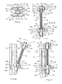
- the panel connector arrangement 40 that comprises the present invention includes the clamp device 42, discrete bottom or lower seating hook 44 (see Figure 2, but note also the forms of Figures 11 and 14), indexing apertures 46 (see the upper portion of Figure 2) of quadrilateral configuration formed in the web portions 22 of the respective members 20 that are equal in size and are spaced the same specific dimension below the tops 36 of the respective members 20, and seating hook mounting apertures 48 and 50 (see the lower portion of Figure 2), also of quadrilateral configuration that are also formed in the web portions 22 of the respective channel members 20, which apertures 48 and 50 are of the different sizes and are respectively at the same specific dimensions above the lower ends 38 of the respective channel members 20.
- the seating hook 44 in the form of Figures 2 - 10 includes a finger portion 51 that is to be in a frictional binding relation with the channel member 20 of the panel 14 (the panel being mounted) when the channel members 20 of panels 12 and 14 are in full abutting relation at the shoulders 24 and 26 and are shifted into coextensive, top level relation, utilizing clamp device 42 that in effect clamps the channel members 20 of panels 12 and 14 together by clamping the channel member 20 of the panel being attached into the indicated binding relation with seating hook finger 51.
- the cast versions of seating hooks 44A and 44B shown in Figures 11 - 13, and Figure 14, respectively, are similarly equipped, as disclosed hereinafter.
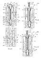
- the clamp device 42 is screw actuated, and includes a threaded bolt 62 having top head 64, shank 66 that is externally threaded as 68, a bottom head 75, and a pair of special bodies or head members 70 and 72 (hereinafter sometimes referred to as heads) that are spaced apart longitudinally of the screw shank 66 and biased to that position by suitable means, such as the illustrated compression spring 73.
- the bolt heads 64 and 75, and its shank 66 are integral with bolt 62.
- the clamp device 42 is desirably power actuated, and has an outside or upper side 74 (see the upper portion of Figure 2) and an inside or lower side 76 for body or head member 70, and an inside or upper side 78 and an outside or lower side 80 for the body or head member 72.
- the body or head member 72 is threadedly mounted on the shank 66 of bolt 62, while the body or head member 70 is rotatably mounted on the bolt shank 66, and thus is guided by threading 68 but is not in threaded engagement therewith.
- the bolt 62 bottom head 75 serves to limit the threaded movement of body or head member 72 away from bolt head 64; bolt head 64 is of the type adapted to be rotated by a conventional power drill or the like, as by bolt head 64 being of hex shape and suitably and conventionally detachably keyed to the drill, for achieving the clamping action involved.
- the seating hook 44 of Figures 2 - 10 is of the formed sheet metal type and has a body 81 shaped to define vertically disposed hook portions 82 and 84, in addition to finger 51, and adjacent the finger 51, an outwardly opening locking recess 86 that, in the form illustrated for this type of bottom hook, includes a lower and narrower rectilinear portion 88, and an upper wider portion 90 that diverges in width in an upwardly direction.
- the seating hook locking recess 86 defined by the seating hook body 81 has a lower or base margin 94 (see Figure 2) that is part of finger 51 and is to be in binding engagement with the web portion 22 of channel member 20 of the side frame member 18, when the channel member 20 of side frame member 18 is in full engagement with the corresponding member 20 of panel 12 on the side frame sets of shoulders 24 and 26, as indicated in Figures 2 - 4, and the clamping action of clamp device 42 is effective, as hereinafter disclosed.
- clamp device head member 70 As to the clamp device head member 70 (see Figures 2 and 5), it will be noted that it includes a center section 100, and oppositely disposed side sections 102 and 104, respectively, while as to the clamp device head member 72, it includes a center section 106 and oppositely disposed side sections 108 and 110, respectively.
- the center sections 100 and 106 of the respective head members 70 and 72 are similar except that the bolt shank receiving aperture 112 of the head member 70 is proportioned for slip fit reception over the bolt shank threading 68, while the bore 114 of the head member 72 is suitably internally threaded for threaded engagement with the bolt shank threading 68.
- the bolt head 75 limits the rotational ability of head member 72 away from the bolt head 64, while compression spring 73 biases the head members 70 and 72 in spaced apart relation, and seats head member 70 either directly against the bolt head 64, or against suitable washer 116 that is interposed between the head 64 and member 70 in the illustrated embodiment of clamp device 42.
- the device 42 upper head member 70 its section 104 is formed to define upright but depending lobe 118, of five sided cross sectional configuration (in the plane of bolt 62 as device 2 is shown in Figure 5), and its section 102 is formed to define cross lobe 120 that extends oppositely of lobe 118 and thus crosswise or transversely of bolt 62; sections 102 and 104 of head member 70 are oppositely disposed at either side of bolt 62.
- the head member 72 is similarly formed, its section 108 defining upright lobe 122 (that is similar to lobe 118 but extends toward head member 70), and cross lobe 124 that extends oppositely of the lobe 122 and is of the same size and shape as section 102 of head 70.
- the basic exterior shaping of the respective head members 70 and 72 is made similar for cost saving purposes.
- the upper surfacing 119 of head member 70 (at the clamp device upper side 74) is planar, while the similar surfacing 125 of head member 72 at the clamp device lower side 80 except for the lower protrusion 127 (which is more specifically referred to hereinafter).
- the lobes 118 and 122 of the respective head members 70 and 72 are proportioned at their respective planar end faces or surfaces 126 and 128 to be longer axially of bolt 26 or vertically than the indexing apertures 46, but of sufficient less width than apertures 46, as to readily pass heads 70 and 72 therethrough.
- Apertures 46 and heads 70 and 72 are both of a width to include a portion of the side frame member abutting shoulders 24 and 26 of the panel side frame members 16 and 18 to be secured together by the practice of the present invention to insure a firm clamping action provided by device 42.
- Apertures 46 are also located below the tops 36 of the respective channel members 20 a predetermined distance, as indicated hereinbefore; for instance, the upper ends 46B of the apertures 46 may be located three and one-half inches below the frame member tops 36, and the clamp devices 42 are proportioned lengthwise accordingly, for application of the heads 70 and 72 thereto.
- the respective lobes 118 and 122 each define the respective planar surfaces 126 and 128 that are employed to seat the clamp device 42 against the indented portion 22 of the mounted panel side frame member 20 in the initial positioning of the clamp device 42, as hereinafter described.
- the head member 70 at the device 42 top side 74, is defined by planar surfacing 119 that extends across its sections 100 (except for aperture 112), 102 and 104, and thus extends transversely of the head aperture 112.
- the head member 70 at the clamping device underside 76 involves the head including projecting extension 131 of quadrilateral section (square in the illustrated embodiment of device 42) that also defines a portion of aperture 112, and depending lobe 118 being separated from center section 100 by deep V-groove 132; the cross lobe 120 thereof on the underside 76 thereof defines V shaped groove 134 that merges into the head corner edge 136 that is also formed by angled planar cam surfacing 138 that extends to planar surface 139 of its section 102.
- center section 106 includes an upwardly projecting relatively short portion 157 and downwardly projecting relatively long portion 159 defining a planar end surface 161 against which a second washer 116 is engaged between it and head 75 of bolt 62 (the latter extending through head 72, as already indicated).
- the head portions 157 and 159 are preferably of square transverse cross-sectional configuration, with the head portion 159 being proportioned in thickness to be received in, but substantially fill, the space-between the indented portions 21 of the web portions 22 of the panel side frame members 16 and 18 being secured together, in accordance with the invention; the head portion 157 preferably has a thickness that is less than such thickness.
- the long portion 159 also serves to block out the light that may pass through aligned apertures 34 for applications where a short panel 14 is to be secured to a standard length panel 14 is to be secured to a standard length panel 14 and blank cross openings formed in panel side frame flanges 28 and 30 are opened up for this purpose.
- the cross lobe 120 of the head member 70 defines on either side of same cam surfaces 148 that are similarly but oppositely angled with respect to the axis of the head aperture 112, while the lower head member 72 defines similar cam surfaces 15, which are the same as the respective surfaces 148, but only one of which is shown in the drawings.
- the head member 72 on the device 42 side 80 at lobe 122 of head 72 defines cross groove 152 between protuberance 127 head portion 159 (protuberance 127 being of quadrilateral transverse cross-sectional configuration, as indicated in Figures 2 and 5), and transversely extending planar surface 125 that extends transversely of the axis of the head aperture 114 corner edging 144 substantially parallels the plane of head surface 125.
- the hook body 81 as illustrated comprises a length of metal sheeting, suitably formed from a suitable grade of steel or the like, that is shaped to define the U shaped configuration shown in Figure 4 and thus comprises side portions 160 and 162 that are joined and separated by center portion 164, with the center portion 164 and the adjacent portions of the side portions 160 and 162 defining the finger 71.
- the hook side portions 160 and 162 are suitably formed as indicated in Figure 2 to define a pair of upper hook portions 166 that together form hook portion 82, and lower recessed portions 168 that together form hook portion 84; hook portions 82 and 84 are to be applied through the indexing apertures 50 and 48, respectively, of the freestanding panel side frame member 16, and specifically its web 22, for application to its respective apertures 48 and 50, as will be described hereinafter.
- the lower portions 170 of the upper surfacings of the sides 160 and 162 that define the finger 51 of seating hook 44 also define the rectilinear margins 94 of and on either side of the finger 51, in the illustrated embodiment, where the binding engagement of the frame member 18 and seating hook 44 are to take place.
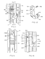
- FIG. 11 - 13 illustrate the bottom hook 44A
- Figure 14 illustrates bottom hook 44B
- the panels, and their side frames 16 and 18, are identical to those of Figures 2 - 10, except that as the panel side frame members 16 and 18, they are suitably formed to define keyhole shaped opening 179, just above the upper seating hook mount aperture 50, as shown in Figure 13.
- the bottom seat hook of Figures 14 also requires the panel side frame members to be formed in this manner.
- the clamp device 42 used in connection with the bottom hook cast versions 44A and 44B may be the same as used in connection with hook 44.
- the bottom hook 44A is formed from a suitable metal, such as zinc or a suitable grade of steel, or their equivalents, that is cast in the form of a hook defining elongate arm 180 having a threaded aperture 182 adjacent its upper end 184 that is to receive screw 186 defining threaded shank 188 and head 190.
- the elongate arm 180 adjacent its lower end 192 is curved hook fashion to define hook portion 194 that forms finger portion 196 having adjacent its upper end 198, on the inside of same, ledge portion 200 that is to serve to bindingly engage the side frame member 18 of the panel being fixed in place (as indicated in Figure 11) similar to what is provided by finger 51 of hook 44 (see Figure 2).
- Bottom hook 44A before panel securement starts using arrangement 40, is applied to the side frame 16 of the fixed panel 12, free of screw 186, by having its arm 180 inserted, with its finger portion 196 disposed upwardly, through the larger aperture 48 of the free standing panel side frame member 16 and moving the hook 44A to an upright position; the hook 44A is shifted until its aperture 182 is aligned with the circular portion 179A of keyhole shaped opening 179, after which screw 186 is turned into aperture 182.
- the hook 44A is then lowered to permit the shank 188 to enter the narrow portion 179B of opening 179 and rest on the side frame 16, and secrew 186 tightened in place to set its head 190 against the side frame member web 22, as indicated in Figure 11, with the hook 44A then being fully supported by the side frame member 16 of the panel 12.
- the basic hook is similar to hook 44A except that its screw 210 is longer than screw 186, it is unthreaded except at the shank end 212, to which nut 214 is threadedly applied, spaced from the side frame member web 22, as needed, to receive the web 22.
- Nut 214 is proportioned to be slipped through the round portion 179A of opening 179, screw 210 and its nut being assembled to its bottom hook as indicated prior to application of the hook 44B as assembled to side frame members 16.
- Nut 214 is also proportioned to be freely received between the shoulders 24 and 26 of the panel side frame 16 to which it is applied.
- Bottom hook 44B in addition to its screw 210 and nut 214, thus comprises elongate arm 220 having aperture 222 (through which screw 210 is inserted) adjacent to its upper end 224.
- Bottom hook 44B before panel securement starts using arrangement 40 is applied to the sided frame 16 of the fixed panel by slipping it between the shoulders 24 and 26 thereof, with the orientation indicated in Figure 14, and then aligning its screw with the round portion 179A of keyhole shaped aperture 179 for slipping same therethrough, after which the hook 44B is lowered into keyhole opening narrow portion 179B to be supported by the panel side frame to which it has been applied, and screw 210 tightened in place.
- the assembler applies the seating hook 44 to the indexing apertures 48 and 50 of the panel side frame member 16 in the position indicated in Figure 2.
- the clamp device 42 is grasped by the assembler and its head members 70 and 72 placed in coplanar relation, essentially in the positioning shown in Figures 2 and 5 - 7.
- the clamp device 42 is first readied as shown in Figure 5, with the head member 70 disposed above the head member 72, and the head member 72 is positioned closely adjacent the stop 75.
- the clamp device 42 is then placed with its planar surfaces 126 and 128 seated within and against the exterior of the web portion 22 (and between shoulders 24 and 26) of the panel side frame member to which the panel 14 is to be attached, and then shifted upwardly along such indented web portion 22 until the lobe 122 of the lower head member 70 is positioned more or less coextensively of such panel side frame indexing aperture 46, after which clamp device 42 is angled as needed (see Figure 6) so that such lobe 122 may be entered into the indexing aperture 46, and clamp device 42 disposed so that at its groove 152 it rests on the lower edge 46A of same.
- the clamp device 42 is then swung back toward the side frame member 16 to bring the surface 126 of head 70 back into said engagement with the web portion 22 (of frame member 16), and shifted upwardly to bring the upper edge 46B of frame member 16 indexing aperture 46 into the V groove 140 of the lower head member 72, which raises the clamp device upper head member 70 to approximately the position shown in Figure 7 with regard to the upper end 36 of the side frame 16.
- the clamp device 42 is dropped within the frame member 16 and positioned to again seat the indicated indexing aperture edge 46A in groove 152 of the lower head member 72, which brings the web portion 22 of the side frame member 16 in question, at the frame member upper end 36, into the groove 132 of the upper head member 70.
- This readies the clamp device for clamping application, to the side frame member 16, for securing to panel 12 the side frame member 18 of the panel 14 that is being applied to the mounted panel 12.
- the side frame member 18 is applied to the seating hook finger portion 51, and its seating hook recess 86, by inserting the finger 51 through the indexing aperture 50 thereof, as indicated in Figure 8.
- the panel 14 is then swung towards the panel 12 to bring the shoulders 24 and 26 of its side frame 18 against the corresponding shoulders 24 and 26 of the side frame member 16, which, during the course of this swinging movement, using the seating hook 44 at its recess 88 as a swinging connection, brings the web portion 22 thereof (of the indented frame member 18) against one or the other of the cam surfaces 138 or 146 of the respective head members 70 and 72 to achieve the side frame member shoulder seating action already indicated, which then permits the panel 14 being secured in place including its side frame 18 to be shifted upwardly so that the web portion 22 (of the indicated frame member 18) thereof enters the groove 134 of head member 70 (see Figure 2).
- the installer then uses a suitable conventional device for power operation of screw bolts to physically seat the indicated side frame member 18 in place, which normally involves an adapter of a conventional type involving the usual shank that is fixedly secured to the tool for rotating purposes, and a head having the usual hex shaped underside aperture proportioned to screw drivingly fit over bolt head 64.
- an adapter of a conventional type involving the usual shank that is fixedly secured to the tool for rotating purposes, and a head having the usual hex shaped underside aperture proportioned to screw drivingly fit over bolt head 64.
- heads 70 and 72 are directed against the web portion 22 of frame member 16, and web portion 22 of frame member 18, which drives the frame member 18 at seating hook 44 into binding engagement with the seating hook marginal surfacings 94; this driving action is continued until the upper ends 36 of the respective panel side frame members (16 and 18) are inessentially level relation.
- bottom hook 44A or bottom hook 44B is employed instead of bottom hook 44, after application of the selected cast bottom hook to anchor same in place on the side frame 16 of the fixed panel 12, the panel securement procedure thereafter is the same as that described in connection with bottom hook 44.
- the panel wall resulting by the securement of the panel 14 to the freestanding panel 12 may be further extended by repeating the procedure indicated for adding additional panels 14 thereto, using a separate clamp device 42 and one of the seating hooks 44, 44A, or 44B for each panel so added the panels 14 so added and the length of the panel wall so provided will be determined by the use to which the work station or the like is to be put.
- right angle corners, or the like may be formed by using suitably contoured filler posts having the securing sides of same formed to approximately and appropriately define the configurations of the illustrated side frame members 16 and 18, with a set forming separate clamp device 42 and one of the hereindisclosed seating hooks being used for each such post, and a similar set being employed on such post for starting a fresh panel wall.
- space subdivider system configurations of the "X", "T", and other conventional configurations may thus be readily put together by the installer.
- Figure 9 illustrates a modified form of the arrangement 40A, in which compression spring 73 is eliminated, and instead a compression spring 235 is interposed between the body or head member 70 and bolt head 64, or washer 116 in the specific form of Figure 9.
- the arrangement 40B includes both springs 73 and 235.
- the arrangements 40A and 40B are otherwise the same as arrangement 40.
- indexing apertures 46, 48 and 50 in set form in the panel side frame members of panels used in a particular work station or the like, panels of varying lengths may be secured together as desired.
- clamp device 42 may be not only premounted as indicated on the free standing panel 12, but also it may be premounted on a panel 14, or a filler post of the type indicated and employed in the manner indicated in conjunction with one of the seating hooks hereindisclosed, to practice the present invention.
Landscapes
- Engineering & Computer Science (AREA)
- Architecture (AREA)
- Physics & Mathematics (AREA)
- Electromagnetism (AREA)
- Civil Engineering (AREA)
- Structural Engineering (AREA)
- Connection Of Plates (AREA)
Applications Claiming Priority (2)
| Application Number | Priority Date | Filing Date | Title |
|---|---|---|---|
| US07/531,400 US5117599A (en) | 1990-05-31 | 1990-05-31 | Panel connector arrangement for office furniture demountable wall panel space divider systems |
| US531400 | 1990-05-31 |
Publications (2)
| Publication Number | Publication Date |
|---|---|
| EP0459653A2 true EP0459653A2 (de) | 1991-12-04 |
| EP0459653A3 EP0459653A3 (en) | 1992-12-16 |
Family
ID=24117471
Family Applications (1)
| Application Number | Title | Priority Date | Filing Date |
|---|---|---|---|
| EP19910304303 Withdrawn EP0459653A3 (en) | 1990-05-31 | 1991-05-14 | Panel connector arrangement for office furniture demountable wall panel space divider systems |
Country Status (4)
| Country | Link |
|---|---|
| US (1) | US5117599A (de) |
| EP (1) | EP0459653A3 (de) |
| AU (1) | AU637555B2 (de) |
| CA (1) | CA2040630C (de) |
Cited By (3)
| Publication number | Priority date | Publication date | Assignee | Title |
|---|---|---|---|---|
| EP0953087A4 (de) * | 1996-11-12 | 2001-05-23 | Shape Corp | Anordnung von mehreren paneelen und verbindungssystem dafür |
| GR1006294B (el) * | 2008-01-11 | 2009-03-09 | Aldeco Ε.Π.Ε. Συστηματα Διαρρυθμισης Χωρων Εργασιας | Διαταξη και μεθοδος συνδεσεως διαχωριστικων γραφειου |
| EP2390453A2 (de) | 2010-05-27 | 2011-11-30 | VKR Holding A/S | Fensteranordnung mit zwei Profilelementen, die mit einer Befestigungsvorrichtung aneinander befestigt sind, und zugehöriges Verfahren |
Families Citing this family (40)
| Publication number | Priority date | Publication date | Assignee | Title |
|---|---|---|---|---|
| US5209035A (en) * | 1991-01-10 | 1993-05-11 | Steelcase Inc. | Utility panel system |
| US5235789A (en) * | 1991-01-11 | 1993-08-17 | Dennis Rackowski | Modular panel system |
| AU688479B2 (en) * | 1994-06-10 | 1998-03-12 | Krueger International, Inc. | Wall system |
| US5490357A (en) * | 1994-06-30 | 1996-02-13 | Ub Office Systems Incorporation | Structure room divider height extension |
| US5694729A (en) * | 1994-09-16 | 1997-12-09 | Panel Concepts, Inc. | Wall partition connector |
| US5746034B1 (en) * | 1994-12-30 | 2000-10-17 | Steelcase Inc | Partition system |
| US5642593A (en) * | 1996-01-17 | 1997-07-01 | Shieh; Steven J. | Knockdown and reassemble office partition |
| US5743055A (en) * | 1996-06-04 | 1998-04-28 | Hon Industries Inc. | Wall panel connector system |
| US6223485B1 (en) * | 1996-06-07 | 2001-05-01 | Herman Miller, Inc. | Wall panel system |
| US6167665B1 (en) | 1996-06-07 | 2001-01-02 | Herman Miller, Inc. | Corner post for a wall panel system |
| US6158178A (en) * | 1997-05-30 | 2000-12-12 | Steelcase Inc. | Panel wall construction |
| US6209273B1 (en) | 1997-05-30 | 2001-04-03 | Steelcase Development Inc. | Panel wall construction |
| US6088980A (en) * | 1997-12-24 | 2000-07-18 | L & P Property Management Company | Space divider system |
| US6128877A (en) * | 1998-03-10 | 2000-10-10 | Steelcase Development Inc. | Variable width end panel |
| US6047508A (en) * | 1998-03-10 | 2000-04-11 | Steelcase Development Inc. | Wall panel partition system |
| US6082065A (en) * | 1998-08-10 | 2000-07-04 | Steelcase Development Inc. | Connector for partition system |
| US6115977A (en) * | 1998-09-11 | 2000-09-12 | Krueger International, Inc. | Knock-down panel partition system |
| US6112485A (en) * | 1998-11-04 | 2000-09-05 | Haworth, Inc. | Post-panel connector arrangement |
| US6230459B1 (en) | 1998-12-04 | 2001-05-15 | Steelcase Development Inc. | Wall start for panel systems |
| US6729085B2 (en) | 2001-02-09 | 2004-05-04 | Herman Miller, Inc. | Wall panel system |
| US6684929B2 (en) | 2002-02-15 | 2004-02-03 | Steelcase Development Corporation | Panel system |
| US6775953B2 (en) | 2002-05-31 | 2004-08-17 | Hon Technology Inc. | Simplified wall panel |
| CA2516083C (en) | 2004-08-17 | 2013-03-12 | Dirtt Environmental Solutions Ltd. | Integrated reconfigurable wall system |
| USRE47132E1 (en) | 2004-08-17 | 2018-11-20 | Dirtt Environmental Solutions, Ltd | Integrated reconfigurable wall system |
| US20070209318A1 (en) * | 2006-03-10 | 2007-09-13 | Mccarthy Ronald | Modular panel assembly |
| US8046965B2 (en) * | 2006-03-10 | 2011-11-01 | Yardistry Limited | Partition system and method of assembling same |
| US20070251179A1 (en) * | 2006-03-10 | 2007-11-01 | Borrowed Spaces, Inc. | Modular panel assembly |
| MX2012002921A (es) * | 2009-10-29 | 2012-04-30 | Krueger Int Inc | Sistema de paneles. |
| WO2013067037A1 (en) * | 2011-10-31 | 2013-05-10 | Bellcomb, Inc. | Tool-less modular panel system |
| US9084489B2 (en) | 2011-12-28 | 2015-07-21 | Dirtt Environmental Solutions, Ltd. | Modular walls incorporating recessed, extendable furniture |
| US9315986B2 (en) * | 2013-02-20 | 2016-04-19 | Freeman Capital Company | Panel support |
| US11085184B2 (en) | 2014-02-20 | 2021-08-10 | Dirtt Environmental Solutions Ltd. | Interface for mounting interchangable components |
| US10058170B2 (en) | 2016-02-10 | 2018-08-28 | Dirtt Environmental Solutions, Ltd | Modular walls with embedded furniture and opposing feature |
| US11093087B2 (en) | 2016-06-10 | 2021-08-17 | Dirtt Environmental Solutions Ltd. | Glass substrates with touchscreen technology |
| US11240922B2 (en) | 2016-06-10 | 2022-02-01 | Dirtt Environmental Solutions Ltd. | Wall system with electronic device mounting assembly |
| EP3482255A4 (de) | 2016-07-08 | 2020-03-11 | DIRTT Environmental Solutions, Ltd. | Intelligentes glas mit niedriger spannung |
| US10842266B2 (en) | 2018-05-23 | 2020-11-24 | Herman Miller, Inc. | Furniture system |
| JP1706495S (ja) * | 2019-11-21 | 2022-02-01 | ビルトイン家電製品付き室内壁用連結部材 | |
| US11457732B2 (en) | 2020-01-10 | 2022-10-04 | MillerKnoll, Inc. | Chase for connecting tables |
| CN119213191A (zh) * | 2022-04-05 | 2024-12-27 | 范罗士股份有限公司 | 模块化墙壁部段的预组装的内部框架 |
Family Cites Families (7)
| Publication number | Priority date | Publication date | Assignee | Title |
|---|---|---|---|---|
| US3430997A (en) * | 1967-05-17 | 1969-03-04 | Miller Herman Inc | Panel joint |
| US3517467A (en) * | 1968-06-17 | 1970-06-30 | Miller Herman Inc | Structural support system for shelving |
| US4443986A (en) * | 1982-03-15 | 1984-04-24 | Stow/Davis Furniture Company | Panel construction system |
| US4567698A (en) * | 1983-12-13 | 1986-02-04 | Knoll International, Inc. | Space divider system |
| US4581869A (en) * | 1983-12-29 | 1986-04-15 | Knoll International, Inc. | Panel construction for an office system |
| USRE32890E (en) * | 1984-08-15 | 1989-03-21 | Herman Miller, Inc. | Frame connector system |
| US4993205A (en) * | 1988-11-23 | 1991-02-19 | The Shaw-Walker Company | Open office system partition panel assembly |
-
1990
- 1990-05-31 US US07/531,400 patent/US5117599A/en not_active Expired - Lifetime
-
1991
- 1991-04-17 AU AU75118/91A patent/AU637555B2/en not_active Ceased
- 1991-04-17 CA CA002040630A patent/CA2040630C/en not_active Expired - Fee Related
- 1991-05-14 EP EP19910304303 patent/EP0459653A3/en not_active Withdrawn
Cited By (3)
| Publication number | Priority date | Publication date | Assignee | Title |
|---|---|---|---|---|
| EP0953087A4 (de) * | 1996-11-12 | 2001-05-23 | Shape Corp | Anordnung von mehreren paneelen und verbindungssystem dafür |
| GR1006294B (el) * | 2008-01-11 | 2009-03-09 | Aldeco Ε.Π.Ε. Συστηματα Διαρρυθμισης Χωρων Εργασιας | Διαταξη και μεθοδος συνδεσεως διαχωριστικων γραφειου |
| EP2390453A2 (de) | 2010-05-27 | 2011-11-30 | VKR Holding A/S | Fensteranordnung mit zwei Profilelementen, die mit einer Befestigungsvorrichtung aneinander befestigt sind, und zugehöriges Verfahren |
Also Published As
| Publication number | Publication date |
|---|---|
| EP0459653A3 (en) | 1992-12-16 |
| US5117599A (en) | 1992-06-02 |
| CA2040630C (en) | 1995-04-25 |
| CA2040630A1 (en) | 1991-12-01 |
| AU7511891A (en) | 1991-12-05 |
| AU637555B2 (en) | 1993-05-27 |
Similar Documents
| Publication | Publication Date | Title |
|---|---|---|
| US5117599A (en) | Panel connector arrangement for office furniture demountable wall panel space divider systems | |
| CA2423121C (en) | Hinge mounting system | |
| US4199907A (en) | Panel joint | |
| EP0982462B1 (de) | Verstellbarer Rahmen | |
| US6220589B1 (en) | Dual action clamp | |
| MX2011007742A (es) | Sistema ajustable para montaje de puertas. | |
| US4942713A (en) | Interconnecting structure for releasably securing successive panels in a relocatable wall | |
| US4979724A (en) | Double action expansion wedge for mounting collar | |
| US4250647A (en) | Fast mount sign hanger | |
| US3178775A (en) | Demountable wall and mounting fixture therefor | |
| EP1042566B1 (de) | Raumeinteilungssystem | |
| US6530302B1 (en) | Cabinetmaking system | |
| US5752291A (en) | Adjustable butt hinge | |
| US20050263662A1 (en) | Support for a pipe clamp | |
| US4834593A (en) | Device for the drilling of wooden panels with a view to their assembly by dowels | |
| US3691966A (en) | Corner attachment for lightweight steel shelving | |
| IL113886A (en) | Clamp for venetian blinds | |
| US4204665A (en) | Panel mounting assembly | |
| JPS588113Y2 (ja) | 棚類の取付具 | |
| EP1445412B1 (de) | Verstellbarer Rahmen | |
| EP4610455A1 (de) | Torpfosten | |
| JPH0748331Y2 (ja) | マグネットベースを具えた携帯式穿孔機の取付け装置 | |
| EP4610454A1 (de) | Torpfosten | |
| JP2742776B2 (ja) | 自動販売機固定装置 | |
| JPS585877Y2 (ja) | 空気調和機の窓据付装置 |
Legal Events
| Date | Code | Title | Description |
|---|---|---|---|
| PUAI | Public reference made under article 153(3) epc to a published international application that has entered the european phase |
Free format text: ORIGINAL CODE: 0009012 |
|
| AK | Designated contracting states |
Kind code of ref document: A2 Designated state(s): BE DE FR GB LU NL |
|
| PUAL | Search report despatched |
Free format text: ORIGINAL CODE: 0009013 |
|
| AK | Designated contracting states |
Kind code of ref document: A3 Designated state(s): BE DE FR GB LU NL |
|
| STAA | Information on the status of an ep patent application or granted ep patent |
Free format text: STATUS: THE APPLICATION IS DEEMED TO BE WITHDRAWN |
|
| 18D | Application deemed to be withdrawn |
Effective date: 19930617 |