EP0459319B1 - Hopper for distributing pulverulent material, in particular feed, in feedtroughs for animal battery cages - Google Patents
Hopper for distributing pulverulent material, in particular feed, in feedtroughs for animal battery cages Download PDFInfo
- Publication number
- EP0459319B1 EP0459319B1 EP91108461A EP91108461A EP0459319B1 EP 0459319 B1 EP0459319 B1 EP 0459319B1 EP 91108461 A EP91108461 A EP 91108461A EP 91108461 A EP91108461 A EP 91108461A EP 0459319 B1 EP0459319 B1 EP 0459319B1
- Authority
- EP
- European Patent Office
- Prior art keywords
- chute
- accordance
- feeding
- deflector
- deflectors
- Prior art date
- Legal status (The legal status is an assumption and is not a legal conclusion. Google has not performed a legal analysis and makes no representation as to the accuracy of the status listed.)
- Expired - Lifetime
Links
- 241001465754 Metazoa Species 0.000 title claims description 4
- 239000013590 bulk material Substances 0.000 claims description 3
- 244000144977 poultry Species 0.000 claims description 2
- 239000010410 layer Substances 0.000 claims 1
- 239000002356 single layer Substances 0.000 claims 1
- 230000000694 effects Effects 0.000 description 3
- 239000002184 metal Substances 0.000 description 3
- 230000015572 biosynthetic process Effects 0.000 description 2
- 238000005192 partition Methods 0.000 description 2
- 238000009825 accumulation Methods 0.000 description 1
- 230000006978 adaptation Effects 0.000 description 1
- 238000005056 compaction Methods 0.000 description 1
- 230000006835 compression Effects 0.000 description 1
- 238000007906 compression Methods 0.000 description 1
- 244000144972 livestock Species 0.000 description 1
- 238000012423 maintenance Methods 0.000 description 1
- 238000004519 manufacturing process Methods 0.000 description 1
Images

Classifications
-
- A—HUMAN NECESSITIES
- A01—AGRICULTURE; FORESTRY; ANIMAL HUSBANDRY; HUNTING; TRAPPING; FISHING
- A01K—ANIMAL HUSBANDRY; AVICULTURE; APICULTURE; PISCICULTURE; FISHING; REARING OR BREEDING ANIMALS, NOT OTHERWISE PROVIDED FOR; NEW BREEDS OF ANIMALS
- A01K31/00—Housing birds
- A01K31/14—Nest-boxes, e.g. for singing birds or the like
- A01K31/16—Laying nests for poultry; Egg collecting
- A01K31/17—Laying batteries including auxiliary features, e.g. feeding, watering, demanuring, heating, ventilation
-
- A—HUMAN NECESSITIES
- A01—AGRICULTURE; FORESTRY; ANIMAL HUSBANDRY; HUNTING; TRAPPING; FISHING
- A01K—ANIMAL HUSBANDRY; AVICULTURE; APICULTURE; PISCICULTURE; FISHING; REARING OR BREEDING ANIMALS, NOT OTHERWISE PROVIDED FOR; NEW BREEDS OF ANIMALS
- A01K39/00—Feeding or drinking appliances for poultry or other birds
- A01K39/01—Feeding devices, e.g. chainfeeders
Definitions
- the invention relates to a chute for distributing free-flowing bulk goods, in particular feed, onto at least one, preferably a plurality of, one above the other, equipped with a conveying means of feeding tracks of a single, preferably multi-day cage battery for livestock, in particular poultry, with an upper pouring opening and with horizontal shaft wall openings for each feeding lane and with deflectors protruding into the chute, which are inclined in the direction of the bulk material.
- a chute of the aforementioned type is known from US-A-44 80 588.
- the deflectors have the function of partition walls which, each individually, delimit a fall area within the shaft from another fall area, the feeding tracks each running through an assigned fall area.
- Each feeding lane is equipped with a means of conveyance, eg a revolving drag chain, which can distribute the feed entered at one end of the feeding lane over the entire length of the feeding lane so that all the animals in a row of cages be evenly supplied with feed.
- Feed is placed in the upper opening of the chute.
- the feeding track extends through shaft wall passages, ie it runs through the interior of the chute.
- Feed in the chute can thus be distributed out of the chute and along the feeding track by the conveying means of the feeding track.
- the chute In the case of multi-day cage batteries, the chute generally extends over the entire height of the cage battery, so that several feeding lanes can be supplied with feed via the chute at the same time. Unused feed is pushed back into the chute by the circulating funding.
- the invention has for its object to design a chute such that bridging is avoided even without the use of driven agitators.
- a drop chute created to achieve this object is characterized in that at least one deflector is arranged above each feeding track in such a way that a free edge of the deflector rests like a scraper on the edges of the feeding track which is open at the top.
- the deflectors are rigid, simple components which are inserted into the chute in such a way that they constantly deflect the flow of the feed from the upper pouring opening to the bottom feed path in each case from the vertical fall direction in which the feed slips. This distraction reduces the tendency to form bridges.
- the deflector divides the height of the feed column located therein, determined by the total height of the chute, into individual sections, so that the compression pressure created by the weight of the feed in the feed column can hardly have an effect such that bridging occurs.
- agitators can be dispensed with entirely.
- the chute works reliably and does not require any energy to operate agitators. Wear does not occur, so that the chute is maintenance-free.
- the manufacturing costs of the chute according to the invention are advantageously reduced to a minimum.
- each deflector rests on the edges of the associated open-top feeding path means that a cavity free of feed is formed under the deflector, with the advantage that unused feed that is returned from a feeding path to the chute is wiped off and unhindered accumulated in the cavity formed can. This avoids a usually unavoidable compaction effect by introducing unused feed into the chute, which would promote bridging.
- Each deflector is preferably a flat plate part which is attached in such a way that it is surrounded by about 3/4 of its circumference by adjacent shaft walls.
- a deflector can consist of a simple sheet metal blank, which is inserted into the chute in such a way that the free cross section of the chute is covered by about half.
- the deflectors are inclined in the direction of the fall so that the feed can slide continuously in the chute.
- An angle of inclination of 20 - 25 ° to the shaft wall has proven to be useful. By changing the angle of inclination, an adaptation to properties such. B. the pourability of the feed used.
- deflectors it has proven to be expedient to mount several deflectors alternately in the chute above.
- the deflectors thus form drop levels for feed that slips.
- the free edges of adjacent bumpers can also be overlapped in the direction of fall.
- each drop shaft two deflectors are expediently arranged between two feeding tracks. If the feed is particularly free-flowing, a deflector can also be sufficient. Of course, more than two deflectors can also be installed in a region between two feeding tracks in a chute.
- the attachment of plate-like deflectors formed from sheet metal blanks is particularly simple and effective in the case of chutes, the free cross section of which is square.
- the effect of the deflectors to avoid bridging can be increased by the fact that each feeding track runs along a shaft wall through the chute.
- the feeding lanes are thus arranged on one side of the chute and do not run through the center thereof.
- This laterally offset arrangement of the feeding tracks is particularly advantageous for the formation of a cavity under the deflector immediately adjacent to a feeding track, since the cavity is delimited by the shaft walls in addition to the underside of the deflector, specifically by the shaft wall from which the deflector is located extends the chute and from the shaft wall along which the feeding track runs.
- each feeding lane has a notch in the area between assigned shaft wall passages, which preferably extends down to the level of the funding.
- the notching also has the advantage that excess feed, which is located in the honing chamber under the deflector, can also escape laterally from the return through the notching.
- a part of a chute 1 is shown schematically.
- the chute has a square cross-section, i.e. its shaft walls delimit a square, free shaft cross section.
- feed is fed into the chute 1 via a pouring opening (not shown), which falls through the chute 1 in the direction of arrow 3.
- a deflector 5 protrudes into the chute 1, which is designed as a plate-like sheet metal part and, as shown here, is inclined in the direction of fall indicated by the arrow 3.
- a feeding track 6 runs through the chute 1 and is connected in a manner known per se with a e.g. revolving conveyor element is equipped so that 6 feed can be withdrawn from the chute 1 via the feeding track.
- the removed feed is fed in the direction of arrow 7 to the cages of a row of cages of a cage battery.
- the deflector 5 is, as shown here, arranged above the feeding track 6 in such a way that its free edge 8 rests like a scraper on the edges 9 of the feeding track 6 open at the top. As a result, a cavity 10 is formed under the deflector, in which unused feed fed back from the feed track 6 can possibly accumulate, as is indicated by the accumulation of feed 11.
- the feeding track 6a is provided, to which a deflector 5a, as described above, is assigned.
- a second deflector 5b protrudes from the shaft wall 4b opposite the shaft wall 4a in the area immediately below the upper feeding track 6, alternately to the deflectors 5 and 5a.
- Notches 12, 12a and 12b denote notches in the edges of the feed tracks 6, 6a facing the inside of the shaft.
- the notches are located in the area between the shaft wall passages assigned to the feeding lanes. Each notch extends down to about the level of the funding in the feed track.
- the chute can be extended as required, if appropriately designed.
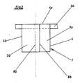
- Fig. 2 shows a side view of the part of a chute 1 shown in Fig. 1.
- Fig. 2 shows that each feeding track 6, 6a, etc. runs along a chute wall 4a through the chute 1, the free edge 8 of the deflector 5 being wiper-like abuts on the edges 9 of the feeding web 6 open at the top.
- Fig. 3 shows a section along the line III-III in Fig. 1 and illustrates how the feeding track 6a runs through the chute 1 along the shaft wall 4a.
- the deflectors 5a and 5b are shown in FIG. 3 in an arrangement in which their free edges 8a, 8b are overlapped in the direction of fall.
Landscapes
- Life Sciences & Earth Sciences (AREA)
- Environmental Sciences (AREA)
- Birds (AREA)
- Animal Husbandry (AREA)
- Biodiversity & Conservation Biology (AREA)
- Zoology (AREA)
- Chutes (AREA)
- Feeding And Watering For Cattle Raising And Animal Husbandry (AREA)
- Feeding Of Articles To Conveyors (AREA)
Description
Die Erfindung betrifft einen Fallschacht zur Verteilung von rieselfähigem Schüttgut, insbesondere Futtermittel, auf wenigstens eine, vorzugsweise mehrere übereinander verlaufende, mit einem Fördermittel ausgerüstete Fütterungsbahnen einer ein-, vorzugsweise mehretagigen Käfigbatterien für Nutztiere, insbesondere Geflügel, mit einer oberen Einschüttöffnung und mit horizontalen Schachtwanddurchlässen für jede Fütterungsbahn und mit in den Fallschacht vorstehenden Abweisern, die in Fallrichtung des Schüttgutes geneigt sind.The invention relates to a chute for distributing free-flowing bulk goods, in particular feed, onto at least one, preferably a plurality of, one above the other, equipped with a conveying means of feeding tracks of a single, preferably multi-day cage battery for livestock, in particular poultry, with an upper pouring opening and with horizontal shaft wall openings for each feeding lane and with deflectors protruding into the chute, which are inclined in the direction of the bulk material.
Ein Fallschacht der vorbezeichneten Gattung ist nach der US-A-44 80 588 bekannt. Bei dem bekannten Fallschacht haben die Abweiser die Funktion von Trennwänden, die, jede für sich, einen Fallbereich innerhalb des Schachtes gegenüber einem anderen Fallbereich abgrenzen, wobei die Fütterungsbahnen durch jeweils einen zugeordneten Fallbereich verlaufen. Jede Fütterungsbahn ist mit einem Fördermittel ausgerüstet, z.B. einer umlaufenden Schleppkette, die das an einem Ende der Fütterungsbahn eingegebene Futtermittel über die gesamte Länge der Fütterungsbahn verteilen kann, damit alle Tiere einer Käfigreihe gleichmäßig mit Futtermittel versorgt werden. Futtermittel wird in die obere Einschüttöffnung des Fallschachtes gegeben. Die Fütterungsbahn erstreckt sich durch Schachtwanddurchlässe, d.h. sie verläuft durch das Innere des Fallschachtes. Im Fallschacht befindliches Futtermittel kann somit vom Fördermittel der Fütterungsbahn aus dem Fallschacht heraus und entlang der Fütterungsbahn verteilt werden. Bei mehretagigen Käfigbatterien erstreckt sich der Fallschacht in der Regel über die gesamte Höhe der Käfigbatterie, so daß mehrere Fütterungsbahnen über den Fallschacht gleichzeitig mit Futtermittel versorgt werden können. Nicht verbrauchtes Futtermittel wird vom umlaufenden Fördermittel wieder zurück in den Fallschacht gedrückt.A chute of the aforementioned type is known from US-A-44 80 588. In the case of the known chute, the deflectors have the function of partition walls which, each individually, delimit a fall area within the shaft from another fall area, the feeding tracks each running through an assigned fall area. Each feeding lane is equipped with a means of conveyance, eg a revolving drag chain, which can distribute the feed entered at one end of the feeding lane over the entire length of the feeding lane so that all the animals in a row of cages be evenly supplied with feed. Feed is placed in the upper opening of the chute. The feeding track extends through shaft wall passages, ie it runs through the interior of the chute. Feed in the chute can thus be distributed out of the chute and along the feeding track by the conveying means of the feeding track. In the case of multi-day cage batteries, the chute generally extends over the entire height of the cage battery, so that several feeding lanes can be supplied with feed via the chute at the same time. Unused feed is pushed back into the chute by the circulating funding.
Im Fallschacht bzw. in den durch als Trennwände wirkende Abweiser abgeteilten Fallbereichen eines Fallschachtes nach der genannten US-A-44 80 588 befindliches Futtermittel neigt zur Brückenbildung. Die Neigung zur Brückenbildung wird noch verstärkt durch in den Fallschacht zurückgedrücktes unverbrauchtes Futtermittel. Dadurch ist eine sichere und gleichmäßige Nachführung des Futtermittels auf jede Fütterungsbahn nicht gewährleistet. Es ist bekannt, der Brückenbildung bei einem Fallschacht dadurch entgegenzuwirken, daß Rührwerke in den Fallschacht eingebaut werden. Für jede vom Fallschacht versorgte Fütterungsbahn ist ein Rührwerk erforderlich. Jedes Rührwerk erfordert einen zugeordneten Antrieb mit entsprechenden Steuerungen. Rührwerke benötigen für ihren Betrieb entsprechende Energie, die bereitgestellt werden muß. Rührwerke und ihre Antriebe sind Verschleiß unterworfen und bedürfen ständiger Wartung.Animal feed in the drop shaft or in the drop areas of a drop shaft, which are separated by baffles acting as partitions, tends to form bridges. The tendency to form bridges is reinforced by unused feed that is pushed back into the chute. As a result, safe and even feeding of the feed to every feeding lane is not guaranteed. It is known to counteract the formation of bridges in a chute by installing agitators in the chute. An agitator is required for each feeding lane supplied by the chute. Each agitator requires an associated drive with appropriate controls. Agitators require appropriate for their operation Energy that has to be provided. Agitators and their drives are subject to wear and require constant maintenance.
Der Erfindung liegt die Aufgabe zugrunde, einen Fallschacht derart auszugestalten, daß auch ohne Verwendung angetriebener Rührwerke eine Brückenbildung vermieden wird.The invention has for its object to design a chute such that bridging is avoided even without the use of driven agitators.
Ein zur Lösung dieser Aufgabe geschaffener Fallschacht zeichnet sich dadurch aus, daß wenigstens ein Abweiser oberhalb jeder Fütterungsbahn derart angeordnet ist, daß eine freie Kante des Abweisers abstreiferartig an den Rändern der oben offenen Fütterungsbahn anliegt.A drop chute created to achieve this object is characterized in that at least one deflector is arranged above each feeding track in such a way that a free edge of the deflector rests like a scraper on the edges of the feeding track which is open at the top.
Bei dem erfindungsgemäßen Fallschacht sind die Abweiser starre, einfache Bauteile, die in den Fallschacht derart eingesetzt sind, daß sie den Strom des Futtermittels von der oberen Einschüttöffnung bis zur jeweils untersten Fütterungsbahn ständig aus der lotrechten Fallrichtung, in der das Futtermittel nachrutscht, ablenken. Durch diese Ablenkung wird die Neigung zur Brückenbildung herabgesetzt. Durch die Abweiser wird die durch die Gesamthöhe des Fallschachtes bestimmte Höhe der darin befindlichen Futtermittelsäule in einzelne Abschnitte unterteilt, so daß sich der durch das Eigengewicht des Futtermittels in der Futtermittelsäule entstehende Verdichtungsdruck kaum derart auswirken kann, daß Brückenbildung auftritt.In the chute according to the invention, the deflectors are rigid, simple components which are inserted into the chute in such a way that they constantly deflect the flow of the feed from the upper pouring opening to the bottom feed path in each case from the vertical fall direction in which the feed slips. This distraction reduces the tendency to form bridges. The deflector divides the height of the feed column located therein, determined by the total height of the chute, into individual sections, so that the compression pressure created by the weight of the feed in the feed column can hardly have an effect such that bridging occurs.
Bei dem erfindungsgemäßen Fallschacht kann auf Rührwerke vollständig verzichtet werden. Der Fallschacht arbeitet betriebssicher und erfordert keine Energie für das Betreiben von Rührwerken. Verschleiß tritt nicht auf, so daß der Fallschacht wartungsfrei ist. Die Herstellungskosten des erfindungsgemäßen Fallschachtes sind mit Vorteil auf ein Minimum reduziert.In the chute according to the invention, agitators can be dispensed with entirely. The chute works reliably and does not require any energy to operate agitators. Wear does not occur, so that the chute is maintenance-free. The manufacturing costs of the chute according to the invention are advantageously reduced to a minimum.
Dadurch, daß eine freie Kante jedes Abweisers an den Rändern der zugeordneten oben offenen Fütterungsbahn anliegt, ist unter dem Abweiser ein futtermittelfreier Hohlraum gebildet, mit dem Vorteil, daß von einer Fütterungsbahn zum Fallschacht zurückgeführtes, unverbrauchtes Futtermittel abgestreift wird und im ausgebildeten Hohlraum unbehindert aufgestaut werden kann. Dadurch wird ein gewöhnlich unvermeidbarer Verdichtungseffekt durch zusätzliches Einführen unverbrauchter Futtermittel in den Fallschacht, der die Brückenbildung fördern würde, vermieden.The fact that a free edge of each deflector rests on the edges of the associated open-top feeding path means that a cavity free of feed is formed under the deflector, with the advantage that unused feed that is returned from a feeding path to the chute is wiped off and unhindered accumulated in the cavity formed can. This avoids a usually unavoidable compaction effect by introducing unused feed into the chute, which would promote bridging.
Jeder Abweiser ist vorzugsweise ein flächiges Plattenteil, das derart angebracht ist, daß es zu etwa 3/4 seines Umfangs von angrenzenden Schachtwänden umgeben ist. Ein Abweiser kann aus einem einfachen Blechzuschnitt bestehen, der so in den Fallschacht eingesetzt wird, daß der freie Querschnitt des Fallschachtes etwa zur Hälfte abgedeckt wird. Damit das Futtermittel im Fallschacht ständig nachrutschen kann, sind die Abweiser in Fallrichtung geneigt. Dabei hat sich ein Neigungswinkel von 20 - 25° zur Schachtwand als zweckmäßig erwiesen. Durch Veränderungen der Neigungswinkel kann eine Anpassung an Eigenschaften, z. B. die Rieselfähigkeit, des jeweils verwendeten Futtermittels vorgenommen werden.Each deflector is preferably a flat plate part which is attached in such a way that it is surrounded by about 3/4 of its circumference by adjacent shaft walls. A deflector can consist of a simple sheet metal blank, which is inserted into the chute in such a way that the free cross section of the chute is covered by about half. The deflectors are inclined in the direction of the fall so that the feed can slide continuously in the chute. An angle of inclination of 20 - 25 ° to the shaft wall has proven to be useful. By changing the angle of inclination, an adaptation to properties such. B. the pourability of the feed used.
Es hat sich als zweckmäßig erwiesen, mehrere Abweiser alternierend in den Fallschacht vorstehend anzubringen. Die Abweiser bilden dadurch Fallstufen für nachrutschendes Futtermittel. Dabei können die freien Kanten einander jeweils benachbarter Abweiser in Fallrichtung auch überlappt sein.It has proven to be expedient to mount several deflectors alternately in the chute above. The deflectors thus form drop levels for feed that slips. The free edges of adjacent bumpers can also be overlapped in the direction of fall.
In jedem Fallschacht sind zweckmäßigerweise zwischen zwei Fütterungsbahnen zwei Abweiser angeordnet. Bei besonders gut rieselfähigem Futtermittel kann auch ein Abweiser ausreichen. Selbstverständlich können auch mehr als zwei Abweiser in einem Bereich zwischen zwei Fütterungsbahnen in einem Fallschacht angebracht sein.In each drop shaft, two deflectors are expediently arranged between two feeding tracks. If the feed is particularly free-flowing, a deflector can also be sufficient. Of course, more than two deflectors can also be installed in a region between two feeding tracks in a chute.
Die Anbringung von aus Blechzuschnitten gebildeten plattenartigen Abweisern ist besonders einfach und wirkungsvoll bei Fallschächten,deren freier Querschnitt vierkantig ist. Bei einem derartigen Fallschacht kann die Wirkung der Abweiser zur Vermeidung von Brückenbildung noch dadurch gesteigert werden, daß jede Fütterungsbahn an einer Schachtwand entlang durch den Fallschacht verläuft. Die Fütterungsbahnen sind somit an einer Seite des Fallschachtes angeordnet und verlaufen nicht durch dessen Zentrum. Diese seitlich versetzte Anordnung der Fütterungsbahnen ist besonders vorteilhaft für die Ausbildung eines Hohlraumes unter dem einer Fütterungsbahn unmittelbar benachbarten Abweiser, da der Hohlraum zusätzlich zur Unterseite des Abweisers noch durch die Schachtwände begrenzt wird, und zwar durch die Schachtwand, von der aus sich der Abweiser in den Fallschacht erstreckt und von der Schachtwand, entlang der die Fütterungsbahn verläuft.The attachment of plate-like deflectors formed from sheet metal blanks is particularly simple and effective in the case of chutes, the free cross section of which is square. At a such a chute, the effect of the deflectors to avoid bridging can be increased by the fact that each feeding track runs along a shaft wall through the chute. The feeding lanes are thus arranged on one side of the chute and do not run through the center thereof. This laterally offset arrangement of the feeding tracks is particularly advantageous for the formation of a cavity under the deflector immediately adjacent to a feeding track, since the cavity is delimited by the shaft walls in addition to the underside of the deflector, specifically by the shaft wall from which the deflector is located extends the chute and from the shaft wall along which the feeding track runs.
Damit sich auch in der Fütterungsbahn selbst keine Brücke bildet, ist nach einer vorteilhaften Weiterbildung vorgesehen, daß der Rand jeder Fütterungsbahn im Bereich zwischen zugeordneten Schachtwanddurchlässen eine Ausklinkung aufweist, die vorzugsweise bis auf die Höhe des Fördermittels hinabreicht. Die Ausklinkung hat auch den Vorteil, daß überschüssiges Futter, das sich im Honlraum unter dem Abweiser befindet, auch aus dem Rücklauf durch die Ausklinkung seitlich entweichen kann.So that no bridge is formed in the feeding lane itself, according to an advantageous further development it is provided that the edge of each feeding lane has a notch in the area between assigned shaft wall passages, which preferably extends down to the level of the funding. The notching also has the advantage that excess feed, which is located in the honing chamber under the deflector, can also escape laterally from the return through the notching.
Eine Ausführungsbeispiel, aus dem sich weitere erfinderische Merkmale ergeben, ist in der Zeichnung dargestellt. Es zeigen:
- Fig. 1 eine schematische Teilansicht eines Fallschachtes für eine mehretagige Käfigbatterie mit drei übereinander verlaufenden Fütterungsbahnen,
- Fig. 2 eine Seitenansicht des Teils eines Fallschachtes gemäß Fig. 1 und
- Fig. 3 eine schematische Schnittansicht entlang der Linie III-III in Fig. 1.
- Fig. 1 is a schematic partial view of a chute for a multi-day cage battery with three feeding tracks running one above the other,
- Fig. 2 is a side view of part of a chute according to Fig. 1 and
- 3 shows a schematic sectional view along the line III-III in FIG. 1.
In Fig. 1 ist ein Teil eines Fallschachtes 1 schematisch dargestellt. Der Fallschacht weist Vierkantquerschnitt auf, d.h. seine Schachtwände begrenzen einen viereckigen freien Schachtquerschnitt. Von oben wird über eine nicht weiter dargestellte Einschüttöffnung 2 Futtermittel in den Fallschacht 1 eingegeben, das in Richtung des Pfeils 3 durch den Fallschacht 1 fällt. Ausgehend von der rechten Schachtwand 4 steht in den Fallschacht 1 ein Abweiser 5 vor, der als plattenartiges Blechteil ausgebildet ist und, wie hier dargestellt, in der durch den Pfeil 3 angegebenen Fallrichtung geneigt ist. Durch den Fallschacht 1 verläuft eine Fütterungsbahn 6, die in an sich bekannter Weise mit einem z.B. umlaufenden Förderelement ausgerüstet ist, so daß über die Fütterungsbahn 6 Futtermittel aus dem Fallschacht 1 abgezogen werden kann. Das abgezogene Futtermittel wird in Richtung des Pfeils 7 den Käfigen einer Käfigreihe einer Käfigbatterie zugeführt.In Fig. 1, a part of a chute 1 is shown schematically. The chute has a square cross-section, i.e. its shaft walls delimit a square, free shaft cross section. From above, feed is fed into the chute 1 via a pouring opening (not shown), which falls through the chute 1 in the direction of arrow 3. Starting from the right shaft wall 4, a
Der Abweiser 5 ist, wie hier dargestellt, oberhalb der Fütterungsbahn 6 derart angeordnet, daß seine freie Kante 8 abstreiferartig an den Rändern 9 der oben offenen Fütterungsbahn 6 anliegt. Dadurch ist unter dem Abweiser ein Hohlraum 10 ausgebildet, in dem sich von der Fütterungsbahn 6 zurückgeführtes unverbrauchtes Futtermittel gegebenenfalls aufstauen kann, wie es durch die Futtermittelanhäufung 11 angedeutet ist.The
Für eine darunterliegende Käfigreihe der Käfigbatterie ist die Fütterungsbahn 6a vorgesehen, der ein Abweiser 5a, wie vorbeschrieben, zugeordnet ist. Von der der Schachtwand 4a gegenüberliegenden Schachtwand 4b steht im Bereich unmittelbar unter der oberen Fütterungsbahn 6 ein zweiter Abweiser 5b vor, und zwar alternierend zu den Abweisern 5 und 5a. Unterhalb der zweiten Fütterungsbahn 6a schließt sich ein ebenfalls mit zwei Abweisern ausgerüsteter gleichartig ausgebildeter weiterer Abschnitt des Fallschachtes an.For an underlying row of cages of the cage battery, the
Mit 12,12a und 12b sind Ausklinkungen in den dem Schachtinneren zugekehrten Rändern der Fütterungsbahnen 6,6a bezeichnet. Die Ausklinkungen befinden sich im Bereich zwischen den Fütterungsbahnen zugeordneten Schachtwanddurchlässen. Jede Ausklinkung reicht bis etwa auf die Höhe des in der Fütterungsbahn verlaufenden Fördermittels hinab.
Der Fallschacht kann, entsprechend ausgebildet, beliebig verlängert werden.The chute can be extended as required, if appropriately designed.
Fig. 2 zeigt eine Seitenansicht des in Fig. 1 dargestellten Teils eines Fallschachtes 1. Fig. 2 zeigt, daß jede Fütterungsbahn 6,6a usw. an einer Schachtwand 4a entlang durch den Fallschacht 1 verläuft, wobei die freie Kante 8 des Abweisers 5 abstreiferartig an den Rändern 9 der oben offenen Fütterungsbahn 6 anliegt.Fig. 2 shows a side view of the part of a chute 1 shown in Fig. 1. Fig. 2 shows that each feeding
Fig. 3 zeigt einen Schnitt entlang der Linie III-III in Fig. 1 und verdeutlicht, wie die Fütterungsbahn 6a durch den Fallschacht 1 entlang der Schachtwand 4a verläuft. Die Abweiser 5a und 5b sind in Fig. 3 in einer Anordnung dargestellt, bei der ihre freien Kanten 8a,8b in Fallrichtung überlappt sind.Fig. 3 shows a section along the line III-III in Fig. 1 and illustrates how the
Claims (10)
- A chute (1) for distributing pourable bulk material, in particular feed, onto at least one feeding channel (6) - preferably a plurality of feeding channels (6) running one above the other - equipped with a conveyor, of a single-layer, preferably multi-layer, battery cage for commercial animals, in particular poultry, the chute having an upper charging opening (2), having horizontal chute-wall-openings for each feeding channel and having deflectors (5, 5a, 5b) which project into the chute (1) and are inclined in the direction of fall of the bulk material, characterised in that at least one deflector (5, 5a) is arranged above each feeding channel (6, 6a) in such a manner that a free edge (8, 8a) of the deflector contacts - in the manner of a scraper - the edges (9) of the feeding channel (6, 6a) open at the top.
- A chute in accordance with Claim 1, characterised in that each deflector (5, 5a, 5b) is a planar plate part surrounded on approximately 3/4 of its periphery by adjacent chute walls (4, 4a, 4b).
- A chute in accordance with Claim 1 and 2, characterised in that each deflector (5, 5a, 5b) is inclined at an angle of 20 - 45° to a chute wall (4).
- A chute in accordance with any one of the preceding Claims, characterised in that the deflectors (5, 5a, 5b) are attached to project alternately into the chute (1).
- A chute in accordance with Claim 4, characterised in that the free edges (8, 8a) of neighbouring deflectors (5, 5a, 5b) overlap in the direction of fall.
- A chute in accordance with any one of the preceding Claims, characterised in that two deflectors (5a, 5b) are arranged between two feeding channels (6, 6a).
- A chute in accordance with any one of Claims 1 to 6, characterised in that it is square.
- A chute in accordance with any one of the preceding Claims, characterised in that each feeding channel (6, 6a) runs through the chute (1) along a chute wall (4a).
- A chute in accordance with any one of Claims 1 to 8, characterised in that the edge (9) of each feeding channel (6, 6a) has a notch (12, 12a, 12b) in the region between associated chute wall openings.
- A chute in accordance with Claim 9, characterised in that a notch (12, 12a, 12b) extends down to the level of the conveyor.
Priority Applications (1)
| Application Number | Priority Date | Filing Date | Title |
|---|---|---|---|
| AT91108461T ATE97542T1 (en) | 1990-05-25 | 1991-05-24 | DRUM CHUTE FOR DISTRIBUTING FLOATING BULK MATERIAL, PARTICULARLY FEED, ON FEEDING WAYS OF A CAGE BATTERY FOR FARM ANIMALS. |
Applications Claiming Priority (4)
| Application Number | Priority Date | Filing Date | Title |
|---|---|---|---|
| DE4016794 | 1990-05-25 | ||
| DE4016794 | 1990-05-25 | ||
| DE4019868 | 1990-06-22 | ||
| DE4019868A DE4019868A1 (en) | 1990-05-25 | 1990-06-22 | CASE FOR DISTRIBUTION OF GIANT CAPACITY, IN PARTICULAR FEED, ON FEEDING RAILS OF A CAGE BATTERY FOR FARM ANIMALS |
Publications (2)
| Publication Number | Publication Date |
|---|---|
| EP0459319A1 EP0459319A1 (en) | 1991-12-04 |
| EP0459319B1 true EP0459319B1 (en) | 1993-11-24 |
Family
ID=25893526
Family Applications (1)
| Application Number | Title | Priority Date | Filing Date |
|---|---|---|---|
| EP91108461A Expired - Lifetime EP0459319B1 (en) | 1990-05-25 | 1991-05-24 | Hopper for distributing pulverulent material, in particular feed, in feedtroughs for animal battery cages |
Country Status (3)
| Country | Link |
|---|---|
| EP (1) | EP0459319B1 (en) |
| DE (2) | DE4019868A1 (en) |
| ES (1) | ES2048529T3 (en) |
Families Citing this family (2)
| Publication number | Priority date | Publication date | Assignee | Title |
|---|---|---|---|---|
| DE202013010980U1 (en) | 2013-12-12 | 2015-03-16 | Big Dutchman International Gmbh | Control feed bowl and feeding arrangement for poultry keeping |
| CN114145239B (en) * | 2021-12-31 | 2023-04-25 | 新疆畜牧科学院畜牧研究所 | Feeding device for livestock raising |
Family Cites Families (6)
| Publication number | Priority date | Publication date | Assignee | Title |
|---|---|---|---|---|
| DE1214980B (en) * | 1962-08-30 | 1966-04-21 | Steinmueller Gmbh L & C | Device for breaking up lump-shaped fuels |
| US4480588A (en) * | 1983-08-05 | 1984-11-06 | Cumberland Corporation | Apparatus for raising poultry utilizing high density brooding |
| DE3347439A1 (en) * | 1983-12-29 | 1985-07-18 | Paul 4280 Borken Icking | Device for charging feeding places or troughs |
| NL8403158A (en) * | 1984-10-16 | 1986-05-16 | Malestein Teus | ANIMAL DEVICE AND METHOD. |
| US4690101A (en) * | 1985-05-17 | 1987-09-01 | Peter Kilham | Bird feeder with adjustable feed tray |
| DD269773A1 (en) * | 1987-12-30 | 1989-07-12 | Gefluegelwirtschaft Ing Veb | DEVICE FOR MASS-CONTROLLED FEEDING |
-
1990
- 1990-06-22 DE DE4019868A patent/DE4019868A1/en not_active Withdrawn
-
1991
- 1991-05-24 ES ES91108461T patent/ES2048529T3/en not_active Expired - Lifetime
- 1991-05-24 DE DE91108461T patent/DE59100629D1/en not_active Expired - Fee Related
- 1991-05-24 EP EP91108461A patent/EP0459319B1/en not_active Expired - Lifetime
Also Published As
| Publication number | Publication date |
|---|---|
| DE59100629D1 (en) | 1994-01-05 |
| ES2048529T3 (en) | 1994-03-16 |
| EP0459319A1 (en) | 1991-12-04 |
| DE4019868A1 (en) | 1991-11-28 |
Similar Documents
| Publication | Publication Date | Title |
|---|---|---|
| DE69906829T2 (en) | System for conveying products and transfer device. | |
| DE2749844A1 (en) | BULK GOODS DISTRIBUTION SYSTEM | |
| DE3631557C2 (en) | Combined filling and removal chute for discharge from above for installation in silo cells for free-flowing, break-sensitive bulk goods | |
| DE2525343C3 (en) | Machine frame for chain conveyor | |
| EP0459319B1 (en) | Hopper for distributing pulverulent material, in particular feed, in feedtroughs for animal battery cages | |
| EP0434995B1 (en) | Silo with a discharging device | |
| DE2833628C2 (en) | Reloading device for bulk material dumps | |
| WO1992000006A1 (en) | Drop-shaft for the distribution of fluid loose material, especially fodder, onto fodder channels of a cage battery for livestock | |
| DE19645777C2 (en) | Box feeder | |
| EP0222063B1 (en) | Device for releasing out bulk material from a stockpole | |
| EP0195347B1 (en) | Cutting head of a winning or driving machine | |
| DE2939283A1 (en) | SCRATCH FOR A CHAIN SCRATCH CONVEYOR | |
| DE3402986A1 (en) | Chip conveyor | |
| CH467709A (en) | Conveyor | |
| DE3600277C2 (en) | ||
| EP0027981B1 (en) | Nesting arrangement for poultry farms | |
| DE2213834C2 (en) | Transport device for bulk goods, in particular bunker discharge device | |
| DE807930C (en) | Improvement on the rocker slide | |
| EP0929490A1 (en) | Discharge device for a silo, particularly also for free-flowing bulk material | |
| DE1507685C (en) | Feeding device for an ascending pipe sifter | |
| DE3824529C2 (en) | ||
| DE3334200A1 (en) | Series metering system for concrete works | |
| DEM0001358MA (en) | Device for conveying hard, lumpy material. | |
| DE1217876B (en) | Bunker discharge and mixing device | |
| DE1507685B1 (en) | Feeding device for a riser pipe separator |
Legal Events
| Date | Code | Title | Description |
|---|---|---|---|
| PUAI | Public reference made under article 153(3) epc to a published international application that has entered the european phase |
Free format text: ORIGINAL CODE: 0009012 |
|
| AK | Designated contracting states |
Kind code of ref document: A1 Designated state(s): AT BE CH DE DK ES FR GB GR IT LI LU NL SE |
|
| 17P | Request for examination filed |
Effective date: 19920505 |
|
| 17Q | First examination report despatched |
Effective date: 19920710 |
|
| GRAA | (expected) grant |
Free format text: ORIGINAL CODE: 0009210 |
|
| AK | Designated contracting states |
Kind code of ref document: B1 Designated state(s): AT BE CH DE DK ES FR GB GR IT LI LU NL SE |
|
| PG25 | Lapsed in a contracting state [announced via postgrant information from national office to epo] |
Ref country code: SE Effective date: 19931124 Ref country code: GR Free format text: LAPSE BECAUSE OF FAILURE TO SUBMIT A TRANSLATION OF THE DESCRIPTION OR TO PAY THE FEE WITHIN THE PRESCRIBED TIME-LIMIT Effective date: 19931124 Ref country code: DK Effective date: 19931124 Ref country code: BE Effective date: 19931124 |
|
| REF | Corresponds to: |
Ref document number: 97542 Country of ref document: AT Date of ref document: 19931215 Kind code of ref document: T |
|
| REF | Corresponds to: |
Ref document number: 59100629 Country of ref document: DE Date of ref document: 19940105 |
|
| ITF | It: translation for a ep patent filed |
Owner name: INTERPATENT ST.TECN. BREV. |
|
| REG | Reference to a national code |
Ref country code: ES Ref legal event code: FG2A Ref document number: 2048529 Country of ref document: ES Kind code of ref document: T3 |
|
| GBT | Gb: translation of ep patent filed (gb section 77(6)(a)/1977) |
Effective date: 19940301 |
|
| ET | Fr: translation filed | ||
| PG25 | Lapsed in a contracting state [announced via postgrant information from national office to epo] |
Ref country code: AT Effective date: 19940524 |
|
| PG25 | Lapsed in a contracting state [announced via postgrant information from national office to epo] |
Ref country code: LU Free format text: LAPSE BECAUSE OF NON-PAYMENT OF DUE FEES Effective date: 19940531 Ref country code: LI Effective date: 19940531 Ref country code: CH Effective date: 19940531 |
|
| PLBE | No opposition filed within time limit |
Free format text: ORIGINAL CODE: 0009261 |
|
| STAA | Information on the status of an ep patent application or granted ep patent |
Free format text: STATUS: NO OPPOSITION FILED WITHIN TIME LIMIT |
|
| 26N | No opposition filed | ||
| REG | Reference to a national code |
Ref country code: CH Ref legal event code: PL |
|
| PGFP | Annual fee paid to national office [announced via postgrant information from national office to epo] |
Ref country code: GB Payment date: 19980515 Year of fee payment: 8 |
|
| REG | Reference to a national code |
Ref country code: GB Ref legal event code: 732E |
|
| NLS | Nl: assignments of ep-patents |
Owner name: BIG DUTCHMAN INTERNATIONAL GMBH |
|
| REG | Reference to a national code |
Ref country code: FR Ref legal event code: TP |
|
| REG | Reference to a national code |
Ref country code: ES Ref legal event code: PC2A |
|
| PGFP | Annual fee paid to national office [announced via postgrant information from national office to epo] |
Ref country code: FR Payment date: 19990511 Year of fee payment: 9 |
|
| PG25 | Lapsed in a contracting state [announced via postgrant information from national office to epo] |
Ref country code: GB Free format text: LAPSE BECAUSE OF NON-PAYMENT OF DUE FEES Effective date: 19990524 |
|
| GBPC | Gb: european patent ceased through non-payment of renewal fee |
Effective date: 19990524 |
|
| PG25 | Lapsed in a contracting state [announced via postgrant information from national office to epo] |
Ref country code: FR Free format text: LAPSE BECAUSE OF NON-PAYMENT OF DUE FEES Effective date: 20000428 |
|
| PGFP | Annual fee paid to national office [announced via postgrant information from national office to epo] |
Ref country code: DE Payment date: 20000517 Year of fee payment: 10 |
|
| PGFP | Annual fee paid to national office [announced via postgrant information from national office to epo] |
Ref country code: ES Payment date: 20000522 Year of fee payment: 10 |
|
| PGFP | Annual fee paid to national office [announced via postgrant information from national office to epo] |
Ref country code: NL Payment date: 20000531 Year of fee payment: 10 |
|
| REG | Reference to a national code |
Ref country code: FR Ref legal event code: ST |
|
| PG25 | Lapsed in a contracting state [announced via postgrant information from national office to epo] |
Ref country code: ES Free format text: LAPSE BECAUSE OF NON-PAYMENT OF DUE FEES Effective date: 20010525 |
|
| PG25 | Lapsed in a contracting state [announced via postgrant information from national office to epo] |
Ref country code: NL Free format text: LAPSE BECAUSE OF NON-PAYMENT OF DUE FEES Effective date: 20011201 |
|
| NLV4 | Nl: lapsed or anulled due to non-payment of the annual fee |
Effective date: 20011201 |
|
| PG25 | Lapsed in a contracting state [announced via postgrant information from national office to epo] |
Ref country code: DE Free format text: LAPSE BECAUSE OF NON-PAYMENT OF DUE FEES Effective date: 20020301 |
|
| REG | Reference to a national code |
Ref country code: ES Ref legal event code: FD2A Effective date: 20030303 |
|
| PG25 | Lapsed in a contracting state [announced via postgrant information from national office to epo] |
Ref country code: IT Free format text: LAPSE BECAUSE OF NON-PAYMENT OF DUE FEES Effective date: 20050524 |