EP0459135B1 - Floor plate for false floors in ventilated spaces, particularly in clean rooms - Google Patents
Floor plate for false floors in ventilated spaces, particularly in clean rooms Download PDFInfo
- Publication number
- EP0459135B1 EP0459135B1 EP91106292A EP91106292A EP0459135B1 EP 0459135 B1 EP0459135 B1 EP 0459135B1 EP 91106292 A EP91106292 A EP 91106292A EP 91106292 A EP91106292 A EP 91106292A EP 0459135 B1 EP0459135 B1 EP 0459135B1
- Authority
- EP
- European Patent Office
- Prior art keywords
- perforations
- section
- slots
- hollow profile
- profiled bars
- Prior art date
- Legal status (The legal status is an assumption and is not a legal conclusion. Google has not performed a legal analysis and makes no representation as to the accuracy of the status listed.)
- Expired - Lifetime
Links
- 230000035515 penetration Effects 0.000 abstract 1
- 241001295925 Gegenes Species 0.000 description 1
- 238000010276 construction Methods 0.000 description 1
- 239000002184 metal Substances 0.000 description 1
- 230000002093 peripheral effect Effects 0.000 description 1
- 238000009423 ventilation Methods 0.000 description 1
Images

Classifications
-
- F—MECHANICAL ENGINEERING; LIGHTING; HEATING; WEAPONS; BLASTING
- F24—HEATING; RANGES; VENTILATING
- F24F—AIR-CONDITIONING; AIR-HUMIDIFICATION; VENTILATION; USE OF AIR CURRENTS FOR SCREENING
- F24F13/00—Details common to, or for air-conditioning, air-humidification, ventilation or use of air currents for screening
- F24F13/02—Ducting arrangements
- F24F13/06—Outlets for directing or distributing air into rooms or spaces, e.g. ceiling air diffuser
- F24F13/068—Outlets for directing or distributing air into rooms or spaces, e.g. ceiling air diffuser formed as perforated walls, ceilings or floors
-
- E—FIXED CONSTRUCTIONS
- E04—BUILDING
- E04C—STRUCTURAL ELEMENTS; BUILDING MATERIALS
- E04C2/00—Building elements of relatively thin form for the construction of parts of buildings, e.g. sheet materials, slabs, or panels
- E04C2/30—Building elements of relatively thin form for the construction of parts of buildings, e.g. sheet materials, slabs, or panels characterised by the shape or structure
- E04C2/42—Gratings; Grid-like panels
- E04C2/427—Expanded metal or other monolithic gratings
-
- E—FIXED CONSTRUCTIONS
- E04—BUILDING
- E04F—FINISHING WORK ON BUILDINGS, e.g. STAIRS, FLOORS
- E04F15/00—Flooring
- E04F15/02—Flooring or floor layers composed of a number of similar elements
- E04F15/024—Sectional false floors, e.g. computer floors
- E04F15/02405—Floor panels
- E04F15/02417—Floor panels made of box-like elements
Definitions
- the invention relates to a floor plate for raised floors in ventilated rooms, in particular clean rooms, with a load-bearing grate on which a perforated cover plate is fastened.
- the supporting grate In a known base plate of this type, the supporting grate consists of a group of mutually spaced square tubes which are welded with their ends to two transverse square tubes of the same type.
- the cover plate In this floor plate construction, the cover plate is perforated in strips only in zones, in the areas which coincide with the cavities between the square bars of the grate.
- the non-perforated part of the cover plate of this known base plate therefore comprises a peripheral edge zone, as well as a number of parallel strips over the square tubes of the supporting grate. In this way, only about 60% of the base area of the plate is used for the passage of air or, in other words, the supporting grate blocks about 40% of the base area of the cover plate for the passage of air.
- a floor plate for double floors in ventilated rooms which has a supporting grate on which a perforated cover plate is attached.
- This cover plate is perforated practically evenly over its entire base area.
- the supporting grate is formed by profile bars with a narrow web-shaped section. These web-shaped sections of the profiled bars are arranged on the cover plate perpendicular to the cover plate only at their zones of full cross-section between the perforations and are formed in one piece with the cover plate.
- the invention has for its object to develop a base plate of the type described in such a way that the shortcomings indicated above are eliminated and a practically uniform air passage over the entire base of the base plate or the raised floor made from such base plates is achieved, and this with minimization of Turbulence over the raised floor.
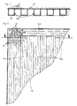
- the hollow profile bars can have a substantially U-shaped cross section and perforations can be provided in the legs and / or in the base section of the U-shaped hollow profile bars.
- the hollow profile bars can have a V-shaped cross section and the perforations can be arranged in both legs of the V-shaped hollow profile bars.
- the perforations in the base section of the U-shaped hollow profile bars can be the perforations in the Correspond to cover plates and be aligned with them This measure brings a further improvement in the air flow.
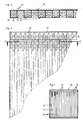
- the double floor plate 10 shown in FIG. 1 from below has a load-bearing grate 11 for a cover plate 12, which is practically uniformly perforated over its entire base area or with elongated holes 13.
- a raised floor numerous raised floor panels 10 are supported with their edges abutting one another on a supporting grid made of profiled bars, which in turn rests on height-adjustable supports.
- the raised floor panels 10 can also be directly supported with their corners on the supports. These supports are set up on the bare floor of the clean room concerned.
- the raised floors produced from the floor slabs 10 according to the invention are designed in particular for clean rooms which are ventilated from the ceiling, the air supplied being able to flow down over the raised floor into the space below the raised floor.
- the cover plate 12 but also the hollow profile bars 14, 14a, 14b or 14c of the supporting grids are perforated, as follows will be explained in detail.
- the grate 11 in the exemplary embodiment according to FIGS. 1-3 has a family of laterally evenly spaced hollow profile bars 14 with a substantially U-shaped cross section. These hollow profile bars 14 are welded at their ends to the aforementioned grate 11 with two transverse hollow profile bars 14 of the same type.
- the grates with the hollow profile bars 14a - 14c (Fig. 7-9) are constructed in the same way as described above.
- the hollow profile bars 14 preferably have the same perforations or elongated holes 13 in their two legs 15 as the cover plate 12. It is also important that the free edges of the legs 15 of the hollow profile bars 14 are only attached to the zones of full cross section of the cover plate 12, except for the free edges of the inner legs 15 of the two transverse hollow profile bars 14 (FIGS. 1 and 3).
- the perforations or elongated holes 13 are provided in the cover plate 13 and in the base section 16 of the U-shaped hollow profile bars 14a, while in the exemplary embodiment according to FIG. 8 the perforations or elongated holes 13 are provided both in the two legs 15 and are worked out in the base section 16 of each U-shaped hollow profile bar 14b of the grate in question.
- the load-bearing grate in the embodiment according to FIG. 9 is composed of hollow profile bars 14c with a V-shaped cross section, the perforations or elongated holes 13 being provided in both legs of each hollow profile bar 14c.
Landscapes
- Engineering & Computer Science (AREA)
- Architecture (AREA)
- General Engineering & Computer Science (AREA)
- Civil Engineering (AREA)
- Structural Engineering (AREA)
- Chemical & Material Sciences (AREA)
- Combustion & Propulsion (AREA)
- Mechanical Engineering (AREA)
- Floor Finish (AREA)
- Ventilation (AREA)
Abstract
Description
Die Erfindung bezieht sich auf eine Bodenplatte für Doppelböden in belüfteten Räumen, insbesondere Reinräumen, mit einem tragenden Rost, auf dem eine perforierte Deckplatte befestigt ist.The invention relates to a floor plate for raised floors in ventilated rooms, in particular clean rooms, with a load-bearing grate on which a perforated cover plate is fastened.
Bei einer bekannten derartigen Bodenplatte besteht der tragende Rost aus einer Schar von gegenseitig beabstandeten Vierkantrohren, welche mit ihren Enden an zwei quer verlaufenden Vierkantrohren gleichen Typs angeschweißt sind. Die Deckplatte ist bei dieser Bodenplattenkonstruktion nur zonenweise streifenförmig perforiert, und zwar in den Bereichen, welche sich mit den Hohlräumen zwischen den Vierkantstäben des Rostes decken. Der nicht perforierte Teil der Deckplatte dieser bekannten Bodenplatte umfaßt daher eine umlaufende Randzone, sowie eine Anzahl paralleler Streifen über den Vierkantrohren des tragenden Rosts. Auf diese Weise werden bei dieser bekannten Bodenplatte nur ca. 60 % der Plattengrundfläche für den Luftdurchtritt genutzt oder anders ausgedrückt, der tragenden Rost blockiert ca. 40 % der Deckplattengrundfläche für den Luftdurchtritt. Dieser Umstand ist im Hinblick auf eine anzustrebende gleichmäßige laminare Luftdurchströmung insbesondere von Reinräumen bzw. Luftabströmung durch einen perforierten Doppelboden nicht akzeptabel. Diese Feststellung gilt auch für andere bekannte Doppelbodenplatten, welche dem gleichen Zweck dienen, nämlich der Entlüftung von insbesondere Reinräumen. Diese Doppelbodenplatten weisen tragende Unterkonstruktionen aus speziell tiefgezogenen Blechen bzw. an der Deckplatte angeformte kreuzförmige Verrippungen auf, enthalten jedoch alle eine umlaufende, nicht perforierte Randzone an der Deckplatte von relativ großer Breite, welche den Luftdurchtritt aus dem Reinraum durch den Doppelboden hindurch beschränkt bzw. zu unerwünschten Luftverwirbelungen über dem Doppelboden führt.In a known base plate of this type, the supporting grate consists of a group of mutually spaced square tubes which are welded with their ends to two transverse square tubes of the same type. In this floor plate construction, the cover plate is perforated in strips only in zones, in the areas which coincide with the cavities between the square bars of the grate. The non-perforated part of the cover plate of this known base plate therefore comprises a peripheral edge zone, as well as a number of parallel strips over the square tubes of the supporting grate. In this way, only about 60% of the base area of the plate is used for the passage of air or, in other words, the supporting grate blocks about 40% of the base area of the cover plate for the passage of air. This circumstance is not acceptable with regard to a desired laminar air flow, in particular from clean rooms or air flow through a perforated raised floor. This statement applies also for other known raised floor panels that serve the same purpose, namely the ventilation of clean rooms in particular. These raised floor panels have load-bearing substructures made from specially deep-drawn sheet metal or cross-shaped ribs formed on the top panel, but all contain a circumferential, non-perforated edge zone on the top panel of relatively large width, which limits or closes the passage of air from the clean room through the raised floor unwanted air turbulence over the raised floor.
Durch die US-A-3 252 400 ist ferner eine Bodenplatte für Doppelböden in belüfteten Räumen bekannt, die einen tragenden Rost aufweist, auf dem eine perforierte Deckplatte befestigt ist. Diese Deckplatte ist praktisch über ihre gesamte Grundfläche gleichmäßig perforiert. Der tragende Rost ist durch Profilstäbe mit einem schmalen stegförmigen Abschnitt gebildet. Diese stegförmigen Abschnitte der Profilstäbe sind an der Deckplatte senkrecht zu dieser nur an deren Zonen vollen Querschnitts zwischen den Perforationen angeordnet und dabei einstückig mit der Deckplatte ausgebildet.From US-A-3 252 400 a floor plate for double floors in ventilated rooms is also known, which has a supporting grate on which a perforated cover plate is attached. This cover plate is perforated practically evenly over its entire base area. The supporting grate is formed by profile bars with a narrow web-shaped section. These web-shaped sections of the profiled bars are arranged on the cover plate perpendicular to the cover plate only at their zones of full cross-section between the perforations and are formed in one piece with the cover plate.
Der Erfindung liegt die Aufgabe zugrunde, eine Bodenplatte der eingangs bezeichneten Bauart derart weiterzubilden, daß die oben aufgezeigten Mängel beseitigt werden und ein praktisch gleichmäßiger Luftdurchtritt über die gesamte Grundfläche der Bodenplatte bzw. des aus solchen Bodenplatten hergestellten Doppelbodens erreicht wird, und dies bei Minimierung von Turbulenzen über dem Doppelboden.The invention has for its object to develop a base plate of the type described in such a way that the shortcomings indicated above are eliminated and a practically uniform air passage over the entire base of the base plate or the raised floor made from such base plates is achieved, and this with minimization of Turbulence over the raised floor.
Gemäß der Erfindung wird obige Aufgabe dadurch gelöst, daß
- a) die Deckplatte praktisch über ihre gesamte Grundfläche gleichmäßig perforiert ist und der tragende Rost aus gleichfalls gleichmäßig perforierten, gegen die Deckplatte hin offenen Hohlprofilstäben besteht und
- b) die freien Ränder der Hohlprofilstäbe an der Deckplatte mindestens überwiegend nur an deren Zonen vollen Querschnitts zwischen den Perforationen befestigt sind.
- a) the cover plate is practically uniformly perforated over its entire base area and the load-bearing grate consists of evenly perforated hollow profile bars open towards the cover plate and
- b) the free edges of the hollow profile bars on the cover plate are at least predominantly attached only to their zones of full cross-section between the perforations.
Bei einem aus solchen Bodenplatten hergestellten Doppelboden wird eine gleichmäßige, turbulenzarme optimale Abströmung der Luft in den Raum unterhalb des Doppelbodens erreicht, so daß diese insbesondere für belüftete Reinräume geeignet ist. Erreicht werden diese Vorteile durch den größeren Durchlaßquerschnitt der Doppelbodenplatten für die abströmende Luft, denn es sind im Gegensatz zum Stand der Technik auch die Rostteile und darüberliegenden Zonen der Deckplatten der Doppelbodenplatten perforiert, d.h. das praktisch die gesamte Doppelbodenfläche gleichmäßig durchbrochen ist.In a raised floor made from such floor panels, a uniform, low-turbulence optimal outflow of air into the space below the raised floor is achieved, so that it is particularly suitable for ventilated clean rooms. These advantages are achieved through the larger passage cross-section of the raised floor panels for the outflowing air, because in contrast to the prior art, the grate parts and overlying zones of the cover panels of the raised floor panels are perforated, i.e. that practically the entire double floor area is evenly broken through.
Ausgestaltungen der Erfindung gehen aus den Unteransprüchen hervor. So können die Hohlprofilstäbe einen im wesentlichen U-förmigen Querschnitt aufweisen und Perforationen können in den Schenkeln und/oder im Basisabschnitt der U-förmigen Hohlprofilstäbe vorgesehen sein.Embodiments of the invention emerge from the subclaims. Thus, the hollow profile bars can have a substantially U-shaped cross section and perforations can be provided in the legs and / or in the base section of the U-shaped hollow profile bars.
Bei einer weiteren Ausführungsform der Erfindung können die Hohlprofilstäbe einen V-förmigen Querschnitt aufweisen und die Perforationen können in beiden Schenkeln der V-förmigen Hohlprofilstäbe angeordnet sein.In a further embodiment of the invention, the hollow profile bars can have a V-shaped cross section and the perforations can be arranged in both legs of the V-shaped hollow profile bars.
Nach noch einer weiteren Ausgestaltung der Erfindung können die Perforationen im Basisabschnitt der U-förmigen Hohlprofilstäbe den Perforationen in der Deckplatten entsprechen und auf diese ausgefluchtet sein Diese Maßnahme bringt eine weitere Verbesserung der Luftdurchströmung.According to yet another embodiment of the invention, the perforations in the base section of the U-shaped hollow profile bars can be the perforations in the Correspond to cover plates and be aligned with them This measure brings a further improvement in the air flow.
Die Erfindung wird anschließend anhand der Zeichnungen von Ausführungsbeispielen erläutert. Es zeigen:
- Fig. 1
- eine Ansicht einer ersten Ausführungsform einer Doppelbodenplatte gemäß der Erfindung von unten, um vorallem den tragenden Rost zu veranschaulichen;
- Fig. 2
- eine Teil-Schnittansicht der Doppelbodenplatte gemäß Fig. 1 entlang der Linie 2-2 in Fig. 3;
- Fig. 3
- eine Teil-Draufsicht der Doppelbodenplatte der Fig. 1 im vergrößerten Maßstab;
- Fig. 4
- eine der Fig. 2 ähnliche Teil-Schnittansicht einer weiteren Ausführungsform einer Doppelbodenplatte gem. der Erfindung und zwar entlang der Linie 4-4 in Fig. 5;
- Fig. 5
- eine Teilansicht der Doppelbodenplatte der Fig. 4 von unten;
- Fig. 6
- einen Ausschnitt aus der Querschnittsansicht der Fig. 2 im vergrößerten Maßstab;
- Fig. 7
- einen Ausschnitt der Querschnittsansicht der Fig. 4 im vergrößerten Maßstab;
- Fig. 8
- eine Teil-Schnittansicht einer weiteren Ausführungsform einer Doppelbodenplatte gem. der Erfindung;
- Fig. 9
- eine Teil-Schnittansicht noch einer weiteren Ausführungsform einer Doppelbodenplatte gemäß der Erfindung.
- Fig. 1
- a view of a first embodiment of a double floor plate according to the invention from below, in particular to illustrate the supporting grate;
- Fig. 2
- a partial sectional view of the raised floor panel according to Figure 1 along the line 2-2 in Fig. 3.
- Fig. 3
- a partial plan view of the raised floor panel of Figure 1 on an enlarged scale.
- Fig. 4
- one of FIG. 2 similar partial sectional view of a further embodiment of a raised floor panel acc. the invention, taken along the line 4-4 in Fig. 5;
- Fig. 5
- a partial view of the double floor plate of Figure 4 from below.
- Fig. 6
- a section of the cross-sectional view of Figure 2 on an enlarged scale.
- Fig. 7
- a section of the cross-sectional view of Figure 4 on an enlarged scale.
- Fig. 8
- a partial sectional view of a further embodiment of a double floor panel acc. the invention;
- Fig. 9
- a partial sectional view of yet another embodiment of a raised floor panel according to the invention.
Die in Fig. 1 von unten gezeigte Doppelbodenplatte 10 weist einen tragenden Rost 11 für eine Deckplatte 12 auf, welche praktisch über ihre gesamte Grundfläche gleichmäßig perforiert bzw. mit Langlöchern 13 durchsetzt ist. Zur Herstellung eines Doppelbodens werden zahlreiche Doppelbodenplatten 10 mit ihren Rändern aneinanderstoßend auf einem Tragraster aus Profilstäben aufgelagert, welches seinerseits auf höhenverstellbaren Stützen ruht. Die Doppelbodenplatten 10 können aber auch unmittelbar mit ihren Ecken auf den Stützen aufgelagert werden. Diese Stützen sind auf dem Rohboden des betreffenden Reinraums aufgestellt. An dieser Stelle soll hervorgehoben werden, daß die aus den erfindungsgemäßen Bodenplatten 10 hergestellten Doppelböden insbesondere für Reinräume konzipiert sind, die von der Decke her belüftet werden, wobei die zugeführte Luft über den Doppelboden nach unten in den Raum unterhalb des Doppelbodens abströmen kann. Damit diese Abströmung der Luft möglichst laminar bzw. turbulenzarm erfolgt, sind nicht nur die Deckplatte 12, sondern auch die Hohlprofilstäbe 14, 14a, 14b oder 14c der tragenden Roste perforiert, wie nachstehend noch im einzelnen erläutert wird.The
Der Rost 11 beim Ausführungsbeispiel nach Fig. 1-3 weist eine Schar von seitlich gleichmäßig beabstandeten Hohlprofilstäben 14 mit im wesentlichen U-förmigen Querschnitt auf. Diese Hohlprofilstäbe 14 sind an ihren Enden mit zwei querverlaufenden gleichartigen Hohlprofilstäben 14 zu dem erwähnten Rost 11 verschweißt. Die Roste mit den Hohlprofilstäben 14a - 14c (Fig. 7-9) sind in gleicher Weise wie vorstehend beschrieben aufgebaut. Die Hohlprofilstäbe 14 weisen in ihren beiden Schenkeln 15 vorzugsweise die gleichen Perforationen bzw. Langlöcher 13 auf wie die Deckplatte 12. Von Bedeutung ist ferner, daß die freien Ränder der Schenkel 15 der Hohlprofilstäbe 14 nur an den Zonen vollen Querschnitts der Deckplatte 12 befestigt sind, ausgenommen lediglich die freien Ränder der inneren Schenkel 15 der beiden querverlaufenden Hohlprofilstäbe 14 (Fig. 1 und 3).The
Beim Ausführungsbeispiel nach Fig. 7 sind die Perforationen bzw. Langlöcher 13 in der Deckplatte 13 sowie im Basisabschnitt 16 der U-förmigen Hohlprofilstäbe 14a vorgesehen, während beim Ausführungsbeispiel nach Fig. 8 die Perforationen bzw. Langlöcher 13 sowohl in den beiden Schenkeln 15 als auch im Basisabschnitt 16 eines jeden U-förmigen Hohlprofilstabs 14b des betreffenden Rostes ausgearbeitet sind.In the exemplary embodiment according to FIG. 7, the perforations or elongated
Der tragende Rost beim Ausführungsbeispiel nach Fig. 9 setzt sich aus Hohlprofilstäben 14c mit V-förmigen Querschnitt zusammen, wobei die Perforationen bzw. Langlöcher 13 in beiden Schenkeln eines jeden Hohlprofilstabes 14c vorgesehen sind.The load-bearing grate in the embodiment according to FIG. 9 is composed of hollow profile bars 14c with a V-shaped cross section, the perforations or elongated
Claims (4)
- A floor plate for false floors in ventilated spaces, in particular clean rooms, with a supporting grid, on which is fixed a perforated top plate, characterized in thata) the top plate (12) is uniformly perforated over practically the whole of its base area (slots 13) and the supporting grid (11) consists of hollow profiled bars open towards the top plate (12) and likewise uniformly perforated, andb) the free edges of the hollow profiled bars (14) are fixed to the top plate (12) at least predominantly only in their regions of full cross-section, in between the perforations (slots 13).
- A floor plate according to claim 1, characterized in that the hollow profiled bars (14, 14a, 14b) have a substantially U-shaped cross-section and the perforations (slots 13) are provided in the arms (15) and/or in the base section (16) of the U-shaped hollow profiled bars (14, 14a, 14b).
- A floor plate according to claim 1, characterized in that the hollow profiled bars (14c) have a V-shaped cross-section and the perforations (slots 13) are arranged in both arms of the V-shaped hollow profiled bars (14c).
- A floor plate according to claim 1 or 2, characterized in that the perforations (slots 13) in the base section (16) of the U-shaped hollow profiled bars (14a, 14b) correspond to the perforations (slots 13) in the top plate ( 12) and are aligned with these.
Applications Claiming Priority (2)
| Application Number | Priority Date | Filing Date | Title |
|---|---|---|---|
| DE4017203 | 1990-05-29 | ||
| DE4017203A DE4017203C1 (en) | 1990-05-29 | 1990-05-29 |
Publications (2)
| Publication Number | Publication Date |
|---|---|
| EP0459135A1 EP0459135A1 (en) | 1991-12-04 |
| EP0459135B1 true EP0459135B1 (en) | 1993-09-22 |
Family
ID=6407374
Family Applications (1)
| Application Number | Title | Priority Date | Filing Date |
|---|---|---|---|
| EP91106292A Expired - Lifetime EP0459135B1 (en) | 1990-05-29 | 1991-04-19 | Floor plate for false floors in ventilated spaces, particularly in clean rooms |
Country Status (5)
| Country | Link |
|---|---|
| EP (1) | EP0459135B1 (en) |
| AT (1) | ATE94937T1 (en) |
| DE (2) | DE4017203C1 (en) |
| DK (1) | DK0459135T3 (en) |
| ES (1) | ES2046817T3 (en) |
Families Citing this family (5)
| Publication number | Priority date | Publication date | Assignee | Title |
|---|---|---|---|---|
| DE4038938A1 (en) * | 1990-04-19 | 1991-11-21 | Manfred Nothdurft | Floor formed from hollow structures - incorporates internal ribs for reinforcement of hollow structures |
| DE4201710A1 (en) * | 1991-09-27 | 1993-04-08 | Ibotec Beschichtungen Gmbh | WALL OR FLOOR PANEL WITH LATTICE BEAM |
| DE20005184U1 (en) * | 2000-03-21 | 2000-06-29 | Vießmann, Hans, Dr. Dr., 95030 Hof | Ventilation plate for room cells |
| DE202005009987U1 (en) * | 2005-06-25 | 2005-09-22 | Ambros Schmelzer & Sohn Gmbh & Co. Kg | Sheet metal ventilation floor for storage of bulk grain products has modular sheet metal strips resting on transverse beams |
| US8733060B2 (en) | 2010-09-09 | 2014-05-27 | Tate Access Floors Leasing, Inc. | Directional grate access floor panel |
Family Cites Families (6)
| Publication number | Priority date | Publication date | Assignee | Title |
|---|---|---|---|---|
| US2180945A (en) * | 1936-08-01 | 1939-11-21 | Burgess Battery Co | Ventilating construction |
| US3252400A (en) * | 1964-02-24 | 1966-05-24 | Jr Joseph Madl | Means providing a coordinated air flow in an enclosure |
| FR2217482B3 (en) * | 1973-02-12 | 1976-11-26 | Thonus Sprl | |
| DE8020658U1 (en) * | 1980-08-01 | 1980-11-06 | Mero-Werke Dr.-Ing. Max Mengeringhausen, Gmbh & Co, 8700 Wuerzburg | DOUBLE FLOOR PANEL WITH AIR PERFORMANCE OPENINGS |
| US4745715A (en) * | 1987-03-23 | 1988-05-24 | Farley Metals, Inc. | Elevated floor plate |
| DE3738444A1 (en) * | 1987-11-12 | 1989-05-24 | Nickel Gmbh Heinrich | DOUBLE FLOOR FOR AIR EXTRACTION FROM ROOMS |
-
1990
- 1990-05-29 DE DE4017203A patent/DE4017203C1/de not_active Expired - Fee Related
-
1991
- 1991-04-19 ES ES199191106292T patent/ES2046817T3/en not_active Expired - Lifetime
- 1991-04-19 DE DE91106292T patent/DE59100398D1/en not_active Expired - Fee Related
- 1991-04-19 EP EP91106292A patent/EP0459135B1/en not_active Expired - Lifetime
- 1991-04-19 AT AT91106292T patent/ATE94937T1/en not_active IP Right Cessation
- 1991-04-19 DK DK91106292.5T patent/DK0459135T3/en active
Also Published As
| Publication number | Publication date |
|---|---|
| EP0459135A1 (en) | 1991-12-04 |
| ES2046817T3 (en) | 1994-02-01 |
| DK0459135T3 (en) | 1993-11-22 |
| DE59100398D1 (en) | 1993-10-28 |
| ATE94937T1 (en) | 1993-10-15 |
| DE4017203C1 (en) | 1991-07-25 |
Similar Documents
| Publication | Publication Date | Title |
|---|---|---|
| DE2800720A1 (en) | FRAMEWORK CONSTRUCTION IN A MODULAR SYSTEM FOR CORRUGATED COVERS | |
| DE602005003313T2 (en) | Device for connecting frame parts | |
| EP0802287A2 (en) | Height adjustable drainage grating | |
| EP0459135B1 (en) | Floor plate for false floors in ventilated spaces, particularly in clean rooms | |
| DE2814713A1 (en) | Dismountable partition | |
| DE2700947C3 (en) | Partition wall, especially for office and retail spaces | |
| DE2312649B2 (en) | HEAT AND / OR MASS EXCHANGER WITH DIRECT CONTACT OF A LIQUID AND A GAS | |
| DE1791593U (en) | DEVICE FOR VENTILATING UNDER PRESSURE FLOWING WATER THROUGH THE OUTDOOR AIR. | |
| DE2455940A1 (en) | Cover for shafts, trenches and service platforms - has grating type sections with reinforcement profiles and walkway anti-slip covering mats | |
| DE69516956T2 (en) | Modular enclosure set to delimit an expandable, enclosed space | |
| EP0607462B1 (en) | False floor | |
| DE2915622C2 (en) | Floor mat made of flexible material and forming a grid-like grate | |
| CH625010A5 (en) | Self-supporting, vertical partition wall and a method of producing the same | |
| DE2422771C3 (en) | Space framework | |
| DE69600425T2 (en) | Flag arrangement | |
| DE8906131U1 (en) | Removable cooling chamber | |
| DE2162462A1 (en) | Device for laying z. B. tile-like floor coverings | |
| AT18280U1 (en) | Kit for a raised bed | |
| DE1559136C2 (en) | Cooling tower | |
| DE2617628A1 (en) | Angle profile bar for construction of support frame - has round and oblong holes with quadratic pattern allowing adjustment in two directions | |
| DE1273763B (en) | Angle bar made of sheet metal for shelves, furniture or the like. | |
| DE3335901C1 (en) | Suspended ceiling formed from polygonal sections | |
| DE19743785C2 (en) | Suspended ceiling | |
| DE19847180C1 (en) | Profile element for construction of uprights for illuminated doorway | |
| DE2805415B1 (en) | Element sieve field |
Legal Events
| Date | Code | Title | Description |
|---|---|---|---|
| PUAI | Public reference made under article 153(3) epc to a published international application that has entered the european phase |
Free format text: ORIGINAL CODE: 0009012 |
|
| 17P | Request for examination filed |
Effective date: 19910522 |
|
| AK | Designated contracting states |
Kind code of ref document: A1 Designated state(s): AT BE CH DE DK ES FR GB GR IT LI LU NL SE |
|
| 17Q | First examination report despatched |
Effective date: 19921124 |
|
| GRAA | (expected) grant |
Free format text: ORIGINAL CODE: 0009210 |
|
| AK | Designated contracting states |
Kind code of ref document: B1 Designated state(s): AT BE CH DE DK ES FR GB GR IT LI LU NL SE |
|
| REF | Corresponds to: |
Ref document number: 94937 Country of ref document: AT Date of ref document: 19931015 Kind code of ref document: T |
|
| REF | Corresponds to: |
Ref document number: 59100398 Country of ref document: DE Date of ref document: 19931028 |
|
| GBT | Gb: translation of ep patent filed (gb section 77(6)(a)/1977) |
Effective date: 19931013 |
|
| ET | Fr: translation filed | ||
| REG | Reference to a national code |
Ref country code: DK Ref legal event code: T3 |
|
| ITF | It: translation for a ep patent filed | ||
| REG | Reference to a national code |
Ref country code: GR Ref legal event code: FG4A Free format text: 3009723 |
|
| REG | Reference to a national code |
Ref country code: ES Ref legal event code: FG2A Ref document number: 2046817 Country of ref document: ES Kind code of ref document: T3 |
|
| EPTA | Lu: last paid annual fee | ||
| PLBE | No opposition filed within time limit |
Free format text: ORIGINAL CODE: 0009261 |
|
| STAA | Information on the status of an ep patent application or granted ep patent |
Free format text: STATUS: NO OPPOSITION FILED WITHIN TIME LIMIT |
|
| 26N | No opposition filed | ||
| EAL | Se: european patent in force in sweden |
Ref document number: 91106292.5 |
|
| REG | Reference to a national code |
Ref country code: CH Ref legal event code: PFA Free format text: MERO-WERKE DR.-ING. MAX MENGERINGHAUSEN GMBH & CO. TRANSFER- MERO SYSTEME GMBH & CO.KG Ref country code: CH Ref legal event code: NV Representative=s name: TROESCH SCHEIDEGGER WERNER AG |
|
| PGFP | Annual fee paid to national office [announced via postgrant information from national office to epo] |
Ref country code: FR Payment date: 19970226 Year of fee payment: 7 |
|
| PGFP | Annual fee paid to national office [announced via postgrant information from national office to epo] |
Ref country code: GB Payment date: 19970314 Year of fee payment: 7 |
|
| PGFP | Annual fee paid to national office [announced via postgrant information from national office to epo] |
Ref country code: GR Payment date: 19970328 Year of fee payment: 7 |
|
| PGFP | Annual fee paid to national office [announced via postgrant information from national office to epo] |
Ref country code: SE Payment date: 19970422 Year of fee payment: 7 Ref country code: BE Payment date: 19970422 Year of fee payment: 7 |
|
| PGFP | Annual fee paid to national office [announced via postgrant information from national office to epo] |
Ref country code: DK Payment date: 19970423 Year of fee payment: 7 Ref country code: AT Payment date: 19970423 Year of fee payment: 7 |
|
| PGFP | Annual fee paid to national office [announced via postgrant information from national office to epo] |
Ref country code: NL Payment date: 19970429 Year of fee payment: 7 Ref country code: CH Payment date: 19970429 Year of fee payment: 7 |
|
| PGFP | Annual fee paid to national office [announced via postgrant information from national office to epo] |
Ref country code: ES Payment date: 19970430 Year of fee payment: 7 |
|
| PGFP | Annual fee paid to national office [announced via postgrant information from national office to epo] |
Ref country code: DE Payment date: 19970614 Year of fee payment: 7 |
|
| PGFP | Annual fee paid to national office [announced via postgrant information from national office to epo] |
Ref country code: LU Payment date: 19970916 Year of fee payment: 7 |
|
| PG25 | Lapsed in a contracting state [announced via postgrant information from national office to epo] |
Ref country code: LU Free format text: LAPSE BECAUSE OF NON-PAYMENT OF DUE FEES Effective date: 19980419 Ref country code: GB Free format text: LAPSE BECAUSE OF NON-PAYMENT OF DUE FEES Effective date: 19980419 Ref country code: AT Free format text: LAPSE BECAUSE OF NON-PAYMENT OF DUE FEES Effective date: 19980419 |
|
| PG25 | Lapsed in a contracting state [announced via postgrant information from national office to epo] |
Ref country code: SE Free format text: LAPSE BECAUSE OF NON-PAYMENT OF DUE FEES Effective date: 19980420 Ref country code: ES Free format text: LAPSE BECAUSE OF NON-PAYMENT OF DUE FEES Effective date: 19980420 |
|
| PG25 | Lapsed in a contracting state [announced via postgrant information from national office to epo] |
Ref country code: LI Free format text: LAPSE BECAUSE OF NON-PAYMENT OF DUE FEES Effective date: 19980430 Ref country code: GR Free format text: LAPSE BECAUSE OF NON-PAYMENT OF DUE FEES Effective date: 19980430 Ref country code: FR Free format text: THE PATENT HAS BEEN ANNULLED BY A DECISION OF A NATIONAL AUTHORITY Effective date: 19980430 Ref country code: DK Free format text: LAPSE BECAUSE OF NON-PAYMENT OF DUE FEES Effective date: 19980430 Ref country code: CH Free format text: LAPSE BECAUSE OF NON-PAYMENT OF DUE FEES Effective date: 19980430 Ref country code: BE Free format text: LAPSE BECAUSE OF NON-PAYMENT OF DUE FEES Effective date: 19980430 |
|
| BERE | Be: lapsed |
Owner name: MERO-WERKE MAX MENGERINGHAUSEN G.M.B.H. & CO. Effective date: 19980430 |
|
| PG25 | Lapsed in a contracting state [announced via postgrant information from national office to epo] |
Ref country code: NL Free format text: LAPSE BECAUSE OF NON-PAYMENT OF DUE FEES Effective date: 19981101 |
|
| GBPC | Gb: european patent ceased through non-payment of renewal fee |
Effective date: 19980419 |
|
| REG | Reference to a national code |
Ref country code: CH Ref legal event code: PL |
|
| NLV4 | Nl: lapsed or anulled due to non-payment of the annual fee |
Effective date: 19981101 |
|
| EUG | Se: european patent has lapsed |
Ref document number: 91106292.5 |
|
| PG25 | Lapsed in a contracting state [announced via postgrant information from national office to epo] |
Ref country code: DE Free format text: LAPSE BECAUSE OF NON-PAYMENT OF DUE FEES Effective date: 19990202 |
|
| REG | Reference to a national code |
Ref country code: FR Ref legal event code: ST |
|
| REG | Reference to a national code |
Ref country code: DK Ref legal event code: EBP |
|
| REG | Reference to a national code |
Ref country code: ES Ref legal event code: FD2A Effective date: 20000403 |
|
| PG25 | Lapsed in a contracting state [announced via postgrant information from national office to epo] |
Ref country code: IT Free format text: LAPSE BECAUSE OF NON-PAYMENT OF DUE FEES;WARNING: LAPSES OF ITALIAN PATENTS WITH EFFECTIVE DATE BEFORE 2007 MAY HAVE OCCURRED AT ANY TIME BEFORE 2007. THE CORRECT EFFECTIVE DATE MAY BE DIFFERENT FROM THE ONE RECORDED. Effective date: 20050419 |