EP0459016A1 - Schnellkupplung - Google Patents
Schnellkupplung Download PDFInfo
- Publication number
- EP0459016A1 EP0459016A1 EP90122570A EP90122570A EP0459016A1 EP 0459016 A1 EP0459016 A1 EP 0459016A1 EP 90122570 A EP90122570 A EP 90122570A EP 90122570 A EP90122570 A EP 90122570A EP 0459016 A1 EP0459016 A1 EP 0459016A1
- Authority
- EP
- European Patent Office
- Prior art keywords
- socket
- claw
- ring
- quick connector
- tube
- Prior art date
- Legal status (The legal status is an assumption and is not a legal conclusion. Google has not performed a legal analysis and makes no representation as to the accuracy of the status listed.)
- Granted
Links
Images


Classifications
-
- F—MECHANICAL ENGINEERING; LIGHTING; HEATING; WEAPONS; BLASTING
- F16—ENGINEERING ELEMENTS AND UNITS; GENERAL MEASURES FOR PRODUCING AND MAINTAINING EFFECTIVE FUNCTIONING OF MACHINES OR INSTALLATIONS; THERMAL INSULATION IN GENERAL
- F16L—PIPES; JOINTS OR FITTINGS FOR PIPES; SUPPORTS FOR PIPES, CABLES OR PROTECTIVE TUBING; MEANS FOR THERMAL INSULATION IN GENERAL
- F16L37/00—Couplings of the quick-acting type
- F16L37/08—Couplings of the quick-acting type in which the connection between abutting or axially overlapping ends is maintained by locking members
- F16L37/084—Couplings of the quick-acting type in which the connection between abutting or axially overlapping ends is maintained by locking members combined with automatic locking
- F16L37/092—Couplings of the quick-acting type in which the connection between abutting or axially overlapping ends is maintained by locking members combined with automatic locking by means of elements wedged between the pipe and the frusto-conical surface of the body of the connector
- F16L37/0927—Couplings of the quick-acting type in which the connection between abutting or axially overlapping ends is maintained by locking members combined with automatic locking by means of elements wedged between the pipe and the frusto-conical surface of the body of the connector the wedge element being axially displaceable for releasing the coupling
-
- F—MECHANICAL ENGINEERING; LIGHTING; HEATING; WEAPONS; BLASTING
- F16—ENGINEERING ELEMENTS AND UNITS; GENERAL MEASURES FOR PRODUCING AND MAINTAINING EFFECTIVE FUNCTIONING OF MACHINES OR INSTALLATIONS; THERMAL INSULATION IN GENERAL
- F16L—PIPES; JOINTS OR FITTINGS FOR PIPES; SUPPORTS FOR PIPES, CABLES OR PROTECTIVE TUBING; MEANS FOR THERMAL INSULATION IN GENERAL
- F16L37/00—Couplings of the quick-acting type
- F16L37/08—Couplings of the quick-acting type in which the connection between abutting or axially overlapping ends is maintained by locking members
- F16L37/084—Couplings of the quick-acting type in which the connection between abutting or axially overlapping ends is maintained by locking members combined with automatic locking
- F16L37/098—Couplings of the quick-acting type in which the connection between abutting or axially overlapping ends is maintained by locking members combined with automatic locking by means of flexible hooks
- F16L37/0982—Couplings of the quick-acting type in which the connection between abutting or axially overlapping ends is maintained by locking members combined with automatic locking by means of flexible hooks with a separate member for releasing the coupling
-
- F—MECHANICAL ENGINEERING; LIGHTING; HEATING; WEAPONS; BLASTING
- F16—ENGINEERING ELEMENTS AND UNITS; GENERAL MEASURES FOR PRODUCING AND MAINTAINING EFFECTIVE FUNCTIONING OF MACHINES OR INSTALLATIONS; THERMAL INSULATION IN GENERAL
- F16L—PIPES; JOINTS OR FITTINGS FOR PIPES; SUPPORTS FOR PIPES, CABLES OR PROTECTIVE TUBING; MEANS FOR THERMAL INSULATION IN GENERAL
- F16L37/00—Couplings of the quick-acting type
- F16L37/08—Couplings of the quick-acting type in which the connection between abutting or axially overlapping ends is maintained by locking members
- F16L37/084—Couplings of the quick-acting type in which the connection between abutting or axially overlapping ends is maintained by locking members combined with automatic locking
- F16L37/098—Couplings of the quick-acting type in which the connection between abutting or axially overlapping ends is maintained by locking members combined with automatic locking by means of flexible hooks
- F16L37/0985—Couplings of the quick-acting type in which the connection between abutting or axially overlapping ends is maintained by locking members combined with automatic locking by means of flexible hooks the flexible hook extending radially inwardly from an outer part and engaging a bead, recess or the like on an inner part
-
- Y—GENERAL TAGGING OF NEW TECHNOLOGICAL DEVELOPMENTS; GENERAL TAGGING OF CROSS-SECTIONAL TECHNOLOGIES SPANNING OVER SEVERAL SECTIONS OF THE IPC; TECHNICAL SUBJECTS COVERED BY FORMER USPC CROSS-REFERENCE ART COLLECTIONS [XRACs] AND DIGESTS
- Y10—TECHNICAL SUBJECTS COVERED BY FORMER USPC
- Y10S—TECHNICAL SUBJECTS COVERED BY FORMER USPC CROSS-REFERENCE ART COLLECTIONS [XRACs] AND DIGESTS
- Y10S285/00—Pipe joints or couplings
- Y10S285/921—Snap-fit
Definitions
- the present invention relates to a connector for piping for connecting hoses which are employed to transfer a fluid such as gasoline, oil, water, air and the like.
- the fitting for piping comprises a cylinder-shaped fitting body 300, annular seal members 500 disposed on an inner peripheral surface of the fitting body 300 and on an outer peripheral surface of a pipe 400 disposed in the fitting body 300, a retainer member 600 disposed in the fitting body 300 and assembled on an outer peripheral surface of the pipe 400 thereby retaining the seal members 500 and the pipe 400 in the fitting body 300.
- the retainer member 600 is made of a flexible material.
- the retainer member 600 includes a tubular portion 661 having an inner diameter substantially equal to an outer diameter of the pipe 400, the tubular portion 661 which includes an annular groove 661a disposed at a rear and having an inner diameter being greater than the inner diameter of the tubular portion 661, and a plurality of leg portions 662 extending from a rear end of the tubular portion 661, bent outwardly and including a concaved groove 662a formed on an outer peripheral surface.
- the retainer member 600 is inserted into the fitting body 300 at the tubular portion 661 thereof.
- the annular groove 661a of the retainer member 600 engages with an annular convexed portion 400a formed on an outer peripheral surface of the pipe 400
- the concaved groove 662a of the retainer member 600 engages with an annular flanged portion 300a formed on an inner peripheral surface of the fitting body 300 at a rear end, thereby holding the pipe 400 in the fitting body 300 and holding the seal members 500 with a front end of the tubular portion 661 by way of a bushing 700.
- the present invention has been developed in view of the above-mentioned circumstances. It is therefore an object of the present invention to provide a quick connector which exhibits a strong engagement force in a direction being perpendicular to an axial direction, thereby giving a high reliability to a piping system.
- the above object can be achieved by a quick connector of the present invention.
- the quick connector comprises: a tubular-shaped first member including a first tube having a predetermined outer diameter and a ring-shaped projection disposed on an outer peripheral surface of the first tube and projecting in a centrifugal direction; a tubular-shaped second member including a socket at an end thereof, the socket including an opening for disposing an end of the first member therein and a tapered regulatory inner peripheral surface having a reducing inner diameter as it approaches to the opening, and covering an end of the first member disposed through the opening; an engager claw member interposed between an inner peripheral surface of the socket and an outer peripheral surface of the first tube in a manner being movable in a direction of a central axis of the socket, the engager claw member including a ring-shaped base, a plurality of arms extending from the ring-shaped base to the opening in a direction of the central axis of the socket, the arms being deformable in a radial direction, and a
- the quick- connector of the present invention includes the regulatory inner peripheral surface formed on an inner peripheral surface of the socket.
- the regulatory inner peripheral surface is formed in a tapered shape whose inner diameter reduces as it apporaches to the opening of the socket. A degree of the taper may be determined as a respective case requires.
- the engager claw member may be provided with either the first member or the second member.
- urging member various springs may be employed, for instance, a coil spring, a leaf spring and the like may be employed therefor.
- the first tube of the first member is inserted into the socket through the opening against an urging force of the urging member.
- the ring-shaped projection of the first member has got over the claw of the engager claw member.
- the engager claw member is urged by the urging force of the urging member in a direction of the central axial of the socket.
- the claw of the engager claw member is pressed onto the tapered regulatory inner peripheral surface of the socket.
- the claw of the engager claw member is urged onto the tapered regulatory inner peripheral surface of the socket of second member by the urging force of the urging member, and thereby the claw is urged to the ring-shaped projection of the first member in a manner tightening and fastening the ring-shaped projection inwardly in a radial direction. Consequently, it is possible not only to enhance an engaging force of the claw of the engager claw member in a direction being perpendicular to an axial direction, but also to attain a strong engaging force in an axial direction. Therefore, the first member and the second member can be connected with a high reliability.
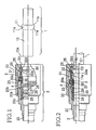
- FIG. 1 through 4 illustrate a side elevation view of the quick connector of the first preferred embodiment partly in section.
- the quick connector of the first preferred embodiment comprises a first member 1, a second member 2, an engager claw member 3 and a spring 4 constituting an urging member.
- the first member 1 includes a first tube 10 made of a metallic pipe and a ring-shaped projection 11 formed on an outer peripheral surface of the first tube 10 and projecting in a centrifugal direction.
- a tapered surface 11a is formed on the ring-shaped projection 11, and a substantially perpendicular rear surface 11b is formed at a rear of the tapered surface 11a.
- a rounded corner 10a is formed at a front end of the first tube 10.
- the second member 2 includes a second tube 20 having a cylindrical shape and a socket 22.
- the socket 22 is screwed on a screw 20a formed on an outer peripheral surface of the second tube 20, and has a cylinder-shaped receiver hole 23.
- an opening 24 is formed in a circular shape
- a tapered regulatory inner peripheral surface 25 is further formed on an inner peripheral surface of the socket 22 at a side of the opening 24 in a ring shape going around an inner peripheral surface of the socket 22.
- the tapered regulatory inner peripheral surface 25 has a taper form whose diameter reduces as it approaches to the opening 24.
- a perpendicular stopper surface 26 is formed at a rear end of the tapered regulatory inner peripheral surface 25 .
- a ring-shaped spring receiver 27 is provided on a stepped portion 20b of the second tube 20. Furthermore, two (2) O-rings 28 and a collar 29 are provided in a central hole 20c of the second tube 20. The O-rings 28 and the collar 29 are thus prevented from coming off by the ring-shaped spring receiver 27.
- the engager claw member 3 is made of resin, and includes a ring-shaped base 30, a plurality of deformable arms 31, and a claw 32 extending from an end of the arms 31.
- the base 30 is equipped with a spring seat surface 30a, provided in the receiver hole 23 of the socket 22, and made movable in a direction of the central axis of the socket 22.
- the claw engager member 3 is equipped with two (2) arms 31 which extend from an axial end surface of the ring-shaped base 30 to the opening 24 of the socket 22 in a direction of the central axis of the socket 22 in a fork-like shape.
- the claw 32 extends from an end of the arms 31, and includes an enagaging surface 32a being substantially perpendicular to the central axis of the socket 22 and a tapered surface 32d inclined with respect to the central axis of the socket 22.
- the spring 4 is a metallic coil spring.
- the spring 4 is positioned in the receiver hole 23 of the socket 22, and interposcd between the spring receiver 27 and the spring seat surface 30a of the base 30 of the engager claw member 3.
- the spring 4 urges the engager claw member 3 to the opening 24 of the socket 22 in a direction of the central axis of the socket 22 as illustrated in Figure 1, thereby bringing the claw 32 of the engager claw member 3 into contact with the tapered regulatory inner peripheral surface 25 and pressing the claw 32 thereof onto the stopper surface 26 simultaneously.
- the first tube 10 of the first member 11 illustrated in Figure 1 is inserted into the receiver hole 23 of the socket 22 of the second member 2 through the opening 24 of the socket 22 of the second member 2.
- the tapered surface 11a of the ring-shaped projection 11 of the first tube 10 pushes up the claw 32 as illustrated in Figure 2, and the arm 31 flexes outwardly in a radial direction, i.e. a direction of the arrow "C2" of Figure 2.
- the spring 4 contracts in an axial direction.
- the claw 32 is heavily pressed inwardly in a radial direction, i.e., in a direction of the arrow "C1" of Figure 4, and thereby the ring-shaped projection 11 of the first member 1 is reliably engaged with the claw 32 of the engager claw member 3.
- the first member 1 and the second member 2 can be connected with ease and in a short period of time in the quick connector of the first preferred embodiment, because the claw 32 of the engager claw member 3 can be automatically engaged with the ring-shaped projection 11 of the first member 11 and the tapered regulatory inner peripheral surface 25 of the second member 2 by simply inserting the first tube 10 of the first member 1 into the socket 22 of the second member 2.
- the first member 1 and the second member 2 are prevented from moving in a direction being perpendicular to an axial direction and in an axial direction getting away from each other, thereby avoiding rickety engagement between the first member 1 and the second member 2 in a direction being perpendicular to an axial direction and in an axial direction.
- an internal pressure acts in a direction pressing the first tube 10, i.e., in a direction of the arrow "D1," during actual service as illustrated in Figure 4, because the second member 2 is placed on a side of a fluid source. Accordingly, the rear surface 11b of the ring-shaped projection 11 of the first tube 10 is in a close contact with the engaging surface 32a of the claw 32.
- the first member 1 and the second member 2 have been prevented from moving freely in a direction being perpendicular to an axial direction and in an axial as aforementioned. Consequently, in the quick connector of the first preferred embodiment, the reliability on the connection of the first member 1 and the second member 2 has been improved remarkably.
- the claw disengaging jig 5 is made of resin, and includes a tube 52 having a through hole 50 and a tapered surface 51 formed at a front end thereof, and a flange 53.
- the following is apparent from Figures 4 and 5: When a front end of the tube 52 of the claw disengaging jig 5 is pressed into the opening 24 of the socket 22, the tapered surface 51a formed at a front end of the claw disengaging jig 5 is pressed onto the tapered surface 32d of the claw 32 of the engager claw member 3.
- the arm 31 of the engaging claw member 3 is flexed and the claw 32 is pushed up outwardly in a radial direction, i.e., in a direction of the arrow "C2" of Figure 4, and thereby the engaging surface 32a of the claw 32 is disengaged from the ring-shaped projection 11.
- the first member 1 and the second member 2 can be disconnected with ease and in a short period of time by pulling apart the first tube 10 of the first member 1 and the second tube 20 of the second member 2 in an axial direction.
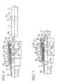
- a quick connector of a second preferred embodiment according to the present invention will be hereinafter described with reference to Figures 6 through 11.
- the quick connector basically has an arrangement similar to that of the quick connector of the first preferred embodiment, and component members performing similar functions and illustrated in Figures 6 through 11 will be designated at the same reference numerals as those of the quick connector of the first preferred embodiment.
- a socket 22 is formed integrally with a second tube 20, and a plurality of openings 22g is formed in a peripheral wall of the socket 22 in a manner penetrating through the peripheral wall of the socket 22, and disposed at predetermined intervals in a circumferential direction of the socket 22.
- the terms "a front end” and “a rear end” as used herein also refer respectively to "a left end” and "a right end” of the component members illustrated in Figures 6 through 11.
- the quick connector of the second preferred embodiment basically operates and effects advantages in a manner similar to that of the quick connector of the first preferred embodiment.
- an engaging force of a claw 32 of an engager claw member 3 can be enhanced in a direction being perpendicular to an axial direction, because the claw 32 is pressed onto a tapered regulatory inner peripheral surface 25 of the socket 22 and urged inwardly in a radial direction, i.e., in a direction of the arrow "C1" of Figure 9, by a spring force of a spring 4 as illustrated in Figure 9.
- the first member 1 and the second member 2 are prevented from getting away from each other in a direction being perpendicular to an axial direction, thereby avoiding the rickety engagement between the first member 1 and the second member 2 in a direction being perpendicular to an axial direction.
- an internal pressure resulting from a fluid flowing in a second tube acts in a direction pressing a first tube 10, i.e., in a direction of the arrow "D1" of Figure 9 during actual service, Accordingly, a rear surface 11b of a ring-shaped projection 11 of the first tube 10 is in a close contact with an engaging surface 32a of the claw 32 as illustrated in Figure 9.
- the engaging force of the claw 32 is enhanced in an axial direction, thereby securely preventing the first member 1 and the second member 2 from getting away from each other in an axial direction.
- the socket 22 of the quick connector is provided with a plurality of the openings 22g which is formed to penetrate through the peripheral wall of the socket 22 and disposed at predetermined intervals in a circumferential direction of the socket 22, the arms 31 and the claws 32 of the engager claw member 3 which are deformed outwardly in a radial direction (or in a direction of the arrow "C2" of Figure 7) can retract into the openings 22 without being interfered with the peripheral wall of the socket 22 when the ring-shaped projection 11 of the first tube 10 gets over the claw 32 of the engager claw member 3 as illustrated in Figure 7. Therefore, this arrangement is advantageous to down-size a radial dimension of the socket 22 by a dimension of the retraction.
- a quick connector includes a first member, a second member, an engager claw member and an urging member.
- the first member includes a first tube and a ring-shaped projection.
- the second member includes a socket at an end thereof, the socket including a tapered regulatory inner peripheral surface.
- the engager claw member is made movable in an axial direction of the socket, disposed in the second member, and includes a ring-shaped base, a plurality of arms being deformable in a radial direction and a claw extending from an end of the arms and engaging with the ring-shaped projection of the first member.
- the urging member presses the engager claw member onto the tapered regulatory inner peripheral surface of the socket, and urged the claw inwardly in a radial direction.
Landscapes
- Engineering & Computer Science (AREA)
- General Engineering & Computer Science (AREA)
- Mechanical Engineering (AREA)
- Quick-Acting Or Multi-Walled Pipe Joints (AREA)
Applications Claiming Priority (2)
| Application Number | Priority Date | Filing Date | Title |
|---|---|---|---|
| JP2144186A JPH0439492A (ja) | 1990-05-31 | 1990-05-31 | クイックコネクタ |
| JP144186/90 | 1990-05-31 |
Publications (2)
| Publication Number | Publication Date |
|---|---|
| EP0459016A1 true EP0459016A1 (de) | 1991-12-04 |
| EP0459016B1 EP0459016B1 (de) | 1995-02-01 |
Family
ID=15356205
Family Applications (1)
| Application Number | Title | Priority Date | Filing Date |
|---|---|---|---|
| EP90122570A Expired - Lifetime EP0459016B1 (de) | 1990-05-31 | 1990-11-26 | Schnellkupplung |
Country Status (4)
| Country | Link |
|---|---|
| US (1) | US5181751A (de) |
| EP (1) | EP0459016B1 (de) |
| JP (1) | JPH0439492A (de) |
| DE (1) | DE69016649T2 (de) |
Cited By (9)
| Publication number | Priority date | Publication date | Assignee | Title |
|---|---|---|---|---|
| DE4413346C1 (de) * | 1994-04-18 | 1995-08-17 | Rasmussen Gmbh | Steckkupplung zum Verbinden zweier Fluidleitungen |
| GB2339873A (en) * | 1998-07-16 | 2000-02-09 | Rasmussen Gmbh | A plug-in coupling for connecting two fluid pipelines |
| EP1106896A1 (de) * | 1999-12-06 | 2001-06-13 | Armaturenfabrik Hermann Voss GmbH + Co. KG | Steckverbindung für Druckmittelsysteme |
| DE19818310B4 (de) * | 1997-04-23 | 2004-04-22 | Yamaha Corp., Hamamatsu | Kupplung zum Verbinden eines rohrförmigen Glieds ohne Verformung des rohrförmigen Glieds aufgrund von Belastungskonzentrationen |
| WO2007073789A1 (de) | 2005-12-16 | 2007-07-05 | A. Raymond Et Cie | Kupplung |
| ES2304841A1 (es) * | 2006-04-24 | 2008-10-16 | Orkli, S.Coop | Sistema de conexion rapida entre un componente valvular y un tubo, componente valvular provisto de dicho sistema de conexion, y accesorio de montaje. |
| WO2012003248A1 (en) * | 2010-07-02 | 2012-01-05 | Schrader-Bridgeport International, Inc. | Connector |
| WO2016091440A1 (de) * | 2014-12-10 | 2016-06-16 | Robert Bosch Gmbh | Steckverbindungsanordnung für medienführende leitungen |
| EP3156726A1 (de) * | 2015-10-16 | 2017-04-19 | Cox Geelen B.V. | Rohrförmiges verbindungsstück und abzweigrohr, insbesondere zur verwendung in einem rohrsystem eines lüftungs- oder rauchgasableitungskanals |
Families Citing this family (57)
| Publication number | Priority date | Publication date | Assignee | Title |
|---|---|---|---|---|
| US5284369A (en) * | 1990-08-24 | 1994-02-08 | Tokai Rubber Industries, Ltd. | Quick connector |
| DE4139124C1 (de) * | 1991-11-28 | 1993-04-01 | Rasmussen Gmbh, 6457 Maintal, De | |
| US5320390A (en) * | 1991-11-29 | 1994-06-14 | Tokai Rubber Industries, Ltd. | Quick connector |
| DE4240136C1 (de) * | 1992-01-10 | 1993-06-17 | Rasmussen Gmbh, 6457 Maintal, De | |
| US5443289A (en) * | 1992-11-11 | 1995-08-22 | Guest; John D. | Tube couplings |
| GB9400585D0 (en) * | 1994-01-13 | 1994-03-09 | Guest John D | Improvements in or relating to tube couplings |
| US5676405A (en) * | 1994-01-14 | 1997-10-14 | The Hoover Company | Quick disconnect coupling |
| JP3113170B2 (ja) * | 1994-12-28 | 2000-11-27 | 株式会社東郷製作所 | コネクタ |
| JP3670191B2 (ja) * | 1994-12-28 | 2005-07-13 | 株式会社東郷製作所 | コネクタ |
| US5887911A (en) * | 1995-10-13 | 1999-03-30 | Form Rite | Quick connect fluid coupling with a self-contained releasable collet retainer |
| US5730475A (en) * | 1995-10-13 | 1998-03-24 | Form Rite | Quick connect fluid coupling with collet retainer |
| US5711553A (en) * | 1996-09-04 | 1998-01-27 | Stmc-Llc | Quick connect fluid coupling |
| DE19809313C1 (de) * | 1998-03-05 | 1999-08-12 | Raymond A & Cie | Verbindungseinheit einer lösbaren Schnellkupplung für Metalleitungen |
| WO2000066921A2 (en) * | 1999-05-04 | 2000-11-09 | Form Rite Corp. | Brake quick connect fluid coupling |
| JP3724360B2 (ja) * | 1999-11-09 | 2005-12-07 | 東海ゴム工業株式会社 | コネクタ |
| US6929289B1 (en) | 2001-02-15 | 2005-08-16 | John Guest International Ltd. | Tube couplings |
| GB0126798D0 (en) * | 2001-11-07 | 2002-01-02 | Guest John Int Ltd | Improvements in or relating to tube couplings |
| GB2387420B (en) | 2002-02-18 | 2004-05-05 | Walterscheid Gmbh Jean | Coupling for connecting hydraulic ducts |
| GB0209897D0 (en) * | 2002-04-30 | 2002-06-05 | Guest John Int Ltd | Improvements in or relating to tube couplings |
| GB0209899D0 (en) | 2002-04-30 | 2002-06-05 | Guest John Int Ltd | Improvements in or relating to tube couplings |
| US7028771B2 (en) * | 2002-05-30 | 2006-04-18 | Clearwater International, L.L.C. | Hydrocarbon recovery |
| US7303553B2 (en) * | 2002-06-24 | 2007-12-04 | Berlin Heart Gmbh | Device for connecting a cannula made of a flexible material with a tube |
| GB0221076D0 (en) * | 2002-09-11 | 2002-10-23 | Guest John Int Ltd | Improvements in or relating to tube couplings |
| JP2005172218A (ja) * | 2003-11-21 | 2005-06-30 | Hama International:Kk | 管継手 |
| US7284772B2 (en) * | 2003-12-19 | 2007-10-23 | Alder Randall F | Coupling assembly |
| US6893051B1 (en) * | 2003-12-31 | 2005-05-17 | Join Top Co., Ltd. | Pipe coupling |
| ATE411489T1 (de) * | 2004-01-27 | 2008-10-15 | Eaton Corp | Kupplungsanordnung mit verriegelungshülse |
| CA2459637C (en) * | 2004-02-27 | 2010-04-27 | Masco Canada Limited | Pipe coupling |
| NZ539383A (en) * | 2004-05-26 | 2006-11-30 | Guest John Int Ltd | Collet for tube couplings with head made of stronger material than rest of collet |
| US7341286B2 (en) * | 2004-12-09 | 2008-03-11 | Cooper Standard Automotive, Inc. | Fluid coupling with dual function retention ring |
| US20060151038A1 (en) * | 2005-01-13 | 2006-07-13 | Saint-Gobain Performance Plastics Corporation | Coiled air brake hose assembly |
| GB0504899D0 (en) * | 2005-03-09 | 2005-04-13 | Guest John Int Ltd | Improvements in or relating to tube couplings |
| US7293758B2 (en) * | 2006-03-10 | 2007-11-13 | Lai Chang Hsueh-Feng | Pipe connector |
| JP2009144740A (ja) * | 2007-12-11 | 2009-07-02 | Onda Seisakusho Seki Kojo:Kk | アダプターを備えた継手 |
| US7506898B1 (en) * | 2008-01-24 | 2009-03-24 | International Business Machines Corporation | Connector and spray shield assembly for liquid cooling of electronics |
| DE102010035853A1 (de) * | 2010-08-30 | 2012-03-01 | Volkswagen Aktiengesellschaft | Verbindungsvorrichtung für die lösbare Aufnahme eines rohrförmigen Einsteckteils mit einem umlaufenden Haltewulst |
| EP2627938B1 (de) | 2010-10-15 | 2018-09-05 | Swagelok Company | Schnell einrastendes leitungsendstück mit hülse |
| US8398122B2 (en) * | 2010-12-30 | 2013-03-19 | Quick Fitting, Inc. | Push connect joint assembly, system and method |
| GB201205575D0 (en) * | 2012-03-29 | 2012-05-16 | Guest John Int Ltd | Improvements in or relating to tube couplings |
| GB201205577D0 (en) * | 2012-03-29 | 2012-05-16 | Guest John Int Ltd | Improvements in or relating to tube couplings |
| JP6067366B2 (ja) * | 2012-12-20 | 2017-01-25 | 住友理工株式会社 | 配管接続構造 |
| CA2919688A1 (en) * | 2013-08-02 | 2015-02-05 | Alternative Fuel Containers, Llc | Fuel gas tank filling system and method |
| DK2857733T3 (en) * | 2013-10-02 | 2017-01-09 | Elaflex Hiby Tanktechnik Gmbh & Co Kg | Combination comprising a hose connector, hose connector and nut |
| KR102248763B1 (ko) | 2013-10-24 | 2021-05-04 | 스와겔로크 컴패니 | 싱글 액션 푸시-투-커넥션 도관 이음쇠 |
| US10458582B2 (en) | 2015-04-23 | 2019-10-29 | Swagelok Company | Single action push to connect conduit fitting with colleting |
| JP6845155B2 (ja) * | 2015-04-23 | 2021-03-17 | スウエイジロク・カンパニー | コレットを有する導管継手の単動押動式接続 |
| US9879810B2 (en) | 2015-09-18 | 2018-01-30 | Quick Fitting, Inc. | Push-to-connect joint assembly with protective shield device and method |
| US9562637B1 (en) | 2015-09-22 | 2017-02-07 | Quick Fitting, Inc. | Locking pipe joint assembly, device and method |
| US9857006B2 (en) | 2016-03-31 | 2018-01-02 | Quick Fitting, Inc. | Retaining ring for pipe joint devices |
| US9671049B1 (en) | 2016-07-27 | 2017-06-06 | Quick Fitting, Inc. | Hybrid push-to-connect fitting device and assembly |
| JP6558643B2 (ja) * | 2016-11-16 | 2019-08-14 | 株式会社タツノ | 充填装置 |
| US10400929B2 (en) | 2017-09-27 | 2019-09-03 | Quick Fitting, Inc. | Fitting device, arrangement and method |
| WO2020205690A1 (en) | 2019-04-01 | 2020-10-08 | Swagelok Company | Push to connect conduit fitting assemblies and arrangements |
| CN110966474B (zh) * | 2019-12-31 | 2021-12-31 | 浙江东辰阀门科技有限公司 | 一种具有快接水嘴的电磁阀 |
| US10969047B1 (en) | 2020-01-29 | 2021-04-06 | Quick Fitting Holding Company, Llc | Electrical conduit fitting and assembly |
| US11035510B1 (en) | 2020-01-31 | 2021-06-15 | Quick Fitting Holding Company, Llc | Electrical conduit fitting and assembly |
| US11105452B1 (en) | 2021-02-25 | 2021-08-31 | Quick Fitting Holding Company, Llc | Push-to-connect joint assembly and device |
Citations (5)
| Publication number | Priority date | Publication date | Assignee | Title |
|---|---|---|---|---|
| GB2089455A (en) * | 1980-12-11 | 1982-06-23 | Medizin Labortechnik Veb K | A plug coupling for gas pipes |
| GB2104607A (en) * | 1981-08-21 | 1983-03-09 | Wilkinson Sword Ltd | Hose couplings |
| EP0306126A1 (de) * | 1987-09-04 | 1989-03-08 | U.S. Plastics Corporation | Schnellkupplung |
| DE3914645A1 (de) * | 1988-05-04 | 1989-11-09 | Rasmussen Gmbh | Steckkupplung zum ankuppeln eines schlauches an ein rohr |
| US4905964A (en) * | 1986-08-29 | 1990-03-06 | Fujipura Seiko Co., Ltd. | Swivelable connector for tubular conduits |
Family Cites Families (5)
| Publication number | Priority date | Publication date | Assignee | Title |
|---|---|---|---|---|
| US4195812A (en) * | 1977-12-27 | 1980-04-01 | Thexton Manufacturing Company | Coupler for grease guns |
| US4601497A (en) * | 1980-10-29 | 1986-07-22 | Proprietary Technology | Swivelable quick connector assembly |
| US4540201A (en) * | 1983-05-16 | 1985-09-10 | Tuthill Corporation | Tube connector |
| US4943091A (en) * | 1988-04-07 | 1990-07-24 | Proprietary Technology, Inc. | Quick connector |
| US4889368A (en) * | 1988-12-12 | 1989-12-26 | Aeroquip Corporation | Combination quick-connect and thread-disconnect tube connector |
-
1990
- 1990-05-31 JP JP2144186A patent/JPH0439492A/ja active Pending
- 1990-11-26 EP EP90122570A patent/EP0459016B1/de not_active Expired - Lifetime
- 1990-11-26 DE DE69016649T patent/DE69016649T2/de not_active Expired - Fee Related
- 1990-11-27 US US07/618,412 patent/US5181751A/en not_active Expired - Fee Related
Patent Citations (5)
| Publication number | Priority date | Publication date | Assignee | Title |
|---|---|---|---|---|
| GB2089455A (en) * | 1980-12-11 | 1982-06-23 | Medizin Labortechnik Veb K | A plug coupling for gas pipes |
| GB2104607A (en) * | 1981-08-21 | 1983-03-09 | Wilkinson Sword Ltd | Hose couplings |
| US4905964A (en) * | 1986-08-29 | 1990-03-06 | Fujipura Seiko Co., Ltd. | Swivelable connector for tubular conduits |
| EP0306126A1 (de) * | 1987-09-04 | 1989-03-08 | U.S. Plastics Corporation | Schnellkupplung |
| DE3914645A1 (de) * | 1988-05-04 | 1989-11-09 | Rasmussen Gmbh | Steckkupplung zum ankuppeln eines schlauches an ein rohr |
Cited By (14)
| Publication number | Priority date | Publication date | Assignee | Title |
|---|---|---|---|---|
| DE4413346C1 (de) * | 1994-04-18 | 1995-08-17 | Rasmussen Gmbh | Steckkupplung zum Verbinden zweier Fluidleitungen |
| US5511827A (en) * | 1994-04-18 | 1996-04-30 | Rasmussen Gmbh | Push-fit connector for joining two fluid lines |
| CN1047834C (zh) * | 1994-04-18 | 1999-12-29 | 拉斯慕森有限公司 | 连接两个流体导管的插接式连接器 |
| DE19818310B4 (de) * | 1997-04-23 | 2004-04-22 | Yamaha Corp., Hamamatsu | Kupplung zum Verbinden eines rohrförmigen Glieds ohne Verformung des rohrförmigen Glieds aufgrund von Belastungskonzentrationen |
| GB2339873B (en) * | 1998-07-16 | 2002-08-28 | Rasmussen Gmbh | A plug-in coupling for connecting two fluid pipelines |
| GB2339873A (en) * | 1998-07-16 | 2000-02-09 | Rasmussen Gmbh | A plug-in coupling for connecting two fluid pipelines |
| US6419281B1 (en) | 1999-12-06 | 2002-07-16 | Armaturenfabrik Hermann Voss Gmbh + Co. | Plug-type connector for compression systems |
| EP1106896A1 (de) * | 1999-12-06 | 2001-06-13 | Armaturenfabrik Hermann Voss GmbH + Co. KG | Steckverbindung für Druckmittelsysteme |
| WO2007073789A1 (de) | 2005-12-16 | 2007-07-05 | A. Raymond Et Cie | Kupplung |
| ES2304841A1 (es) * | 2006-04-24 | 2008-10-16 | Orkli, S.Coop | Sistema de conexion rapida entre un componente valvular y un tubo, componente valvular provisto de dicho sistema de conexion, y accesorio de montaje. |
| WO2012003248A1 (en) * | 2010-07-02 | 2012-01-05 | Schrader-Bridgeport International, Inc. | Connector |
| US20120001418A1 (en) * | 2010-07-02 | 2012-01-05 | Michel Garcin | Connector |
| WO2016091440A1 (de) * | 2014-12-10 | 2016-06-16 | Robert Bosch Gmbh | Steckverbindungsanordnung für medienführende leitungen |
| EP3156726A1 (de) * | 2015-10-16 | 2017-04-19 | Cox Geelen B.V. | Rohrförmiges verbindungsstück und abzweigrohr, insbesondere zur verwendung in einem rohrsystem eines lüftungs- oder rauchgasableitungskanals |
Also Published As
| Publication number | Publication date |
|---|---|
| DE69016649D1 (de) | 1995-03-16 |
| EP0459016B1 (de) | 1995-02-01 |
| JPH0439492A (ja) | 1992-02-10 |
| DE69016649T2 (de) | 1995-06-14 |
| US5181751A (en) | 1993-01-26 |
Similar Documents
| Publication | Publication Date | Title |
|---|---|---|
| US5181751A (en) | Quick connector | |
| US5193857A (en) | Connector | |
| US5284369A (en) | Quick connector | |
| CA2158521C (en) | Quick connect tube couplings | |
| EP1048884B1 (de) | Kupplung zum Verbinden von Flüssigkeitsdurchgängen in einem Flüssigkeitshandhabesystem | |
| US4915136A (en) | Stuffer plug quick connector assembly | |
| EP1099895B1 (de) | Rohrkupplung | |
| EP0667943B1 (de) | Schnellkupplung mit übergangsbereich der kräfte | |
| JP3452599B2 (ja) | 車両用パイプ−コンテナ継手組立体 | |
| EP0628760B1 (de) | Rohranschlussstück | |
| CA2158518A1 (en) | Quick connect tube couplings | |
| US5112085A (en) | Tube coupling with combination retainer and disassembly tool | |
| WO1993020380A1 (en) | Tube coupling with secondary retainer clip | |
| KR100264085B1 (ko) | 자동차 브레이크 시스템용 고압 퀵 커넥터 및 그 제조 방법 | |
| US5320390A (en) | Quick connector | |
| US6945422B2 (en) | In-tank fuel line quick connector assembly | |
| EP1298377B1 (de) | Kupplungsvorrichtung | |
| GB2146400A (en) | Pipe coupling | |
| US6234544B1 (en) | Quick connector with confirmation feature | |
| JPH08178143A (ja) | 目視接続確認可能なクイック・コネクタ継手 | |
| EP0660907B1 (de) | Gesteckte rohranschlussvorrichtung und herstellung | |
| US4653781A (en) | Quick connect coupling assembly | |
| US4978149A (en) | Hose coupling | |
| US5509695A (en) | Precocked quick connect fluid coupling having a v-shaped holding ring | |
| CA1320235C (en) | Quick connect pipe coupling |
Legal Events
| Date | Code | Title | Description |
|---|---|---|---|
| PUAI | Public reference made under article 153(3) epc to a published international application that has entered the european phase |
Free format text: ORIGINAL CODE: 0009012 |
|
| 17P | Request for examination filed |
Effective date: 19901126 |
|
| AK | Designated contracting states |
Kind code of ref document: A1 Designated state(s): DE FR GB |
|
| 17Q | First examination report despatched |
Effective date: 19930309 |
|
| GRAA | (expected) grant |
Free format text: ORIGINAL CODE: 0009210 |
|
| AK | Designated contracting states |
Kind code of ref document: B1 Designated state(s): DE FR GB |
|
| REF | Corresponds to: |
Ref document number: 69016649 Country of ref document: DE Date of ref document: 19950316 |
|
| ET | Fr: translation filed | ||
| PLBE | No opposition filed within time limit |
Free format text: ORIGINAL CODE: 0009261 |
|
| STAA | Information on the status of an ep patent application or granted ep patent |
Free format text: STATUS: NO OPPOSITION FILED WITHIN TIME LIMIT |
|
| 26N | No opposition filed | ||
| PGFP | Annual fee paid to national office [announced via postgrant information from national office to epo] |
Ref country code: GB Payment date: 20011128 Year of fee payment: 12 |
|
| PGFP | Annual fee paid to national office [announced via postgrant information from national office to epo] |
Ref country code: DE Payment date: 20011210 Year of fee payment: 12 |
|
| REG | Reference to a national code |
Ref country code: GB Ref legal event code: IF02 |
|
| PG25 | Lapsed in a contracting state [announced via postgrant information from national office to epo] |
Ref country code: GB Free format text: LAPSE BECAUSE OF NON-PAYMENT OF DUE FEES Effective date: 20021126 |
|
| PG25 | Lapsed in a contracting state [announced via postgrant information from national office to epo] |
Ref country code: DE Free format text: LAPSE BECAUSE OF NON-PAYMENT OF DUE FEES Effective date: 20030603 |
|
| GBPC | Gb: european patent ceased through non-payment of renewal fee | ||
| PGFP | Annual fee paid to national office [announced via postgrant information from national office to epo] |
Ref country code: FR Payment date: 20031110 Year of fee payment: 14 |
|
| PG25 | Lapsed in a contracting state [announced via postgrant information from national office to epo] |
Ref country code: FR Free format text: LAPSE BECAUSE OF NON-PAYMENT OF DUE FEES Effective date: 20050729 |
|
| REG | Reference to a national code |
Ref country code: FR Ref legal event code: ST |