EP0458789B1 - Verfahren und vorrichtung zum trennen von lösemitteln und ölen - Google Patents
Verfahren und vorrichtung zum trennen von lösemitteln und ölen Download PDFInfo
- Publication number
- EP0458789B1 EP0458789B1 EP90900752A EP90900752A EP0458789B1 EP 0458789 B1 EP0458789 B1 EP 0458789B1 EP 90900752 A EP90900752 A EP 90900752A EP 90900752 A EP90900752 A EP 90900752A EP 0458789 B1 EP0458789 B1 EP 0458789B1
- Authority
- EP
- European Patent Office
- Prior art keywords
- gas
- solvent
- oil
- solvent solution
- nozzle
- Prior art date
- Legal status (The legal status is an assumption and is not a legal conclusion. Google has not performed a legal analysis and makes no representation as to the accuracy of the status listed.)
- Expired - Lifetime
Links
- 239000002904 solvent Substances 0.000 title claims abstract description 87
- 238000000034 method Methods 0.000 title claims abstract description 18
- 239000003921 oil Substances 0.000 title claims description 21
- 238000001816 cooling Methods 0.000 claims abstract description 18
- 238000001704 evaporation Methods 0.000 claims description 30
- 230000008020 evaporation Effects 0.000 claims description 30
- 239000003595 mist Substances 0.000 claims description 11
- 239000007921 spray Substances 0.000 claims description 11
- 239000000203 mixture Substances 0.000 claims description 10
- 238000010438 heat treatment Methods 0.000 claims description 4
- 238000001035 drying Methods 0.000 claims description 3
- 238000010533 azeotropic distillation Methods 0.000 abstract 1
- 239000002699 waste material Substances 0.000 abstract 1
- 239000007789 gas Substances 0.000 description 48
- 150000008280 chlorinated hydrocarbons Chemical class 0.000 description 3
- 239000007788 liquid Substances 0.000 description 3
- 238000000926 separation method Methods 0.000 description 3
- IJGRMHOSHXDMSA-UHFFFAOYSA-N Atomic nitrogen Chemical compound N#N IJGRMHOSHXDMSA-UHFFFAOYSA-N 0.000 description 2
- CURLTUGMZLYLDI-UHFFFAOYSA-N Carbon dioxide Chemical compound O=C=O CURLTUGMZLYLDI-UHFFFAOYSA-N 0.000 description 2
- 229930195733 hydrocarbon Natural products 0.000 description 2
- 150000002430 hydrocarbons Chemical class 0.000 description 2
- 239000003507 refrigerant Substances 0.000 description 2
- XSTXAVWGXDQKEL-UHFFFAOYSA-N Trichloroethylene Chemical group ClC=C(Cl)Cl XSTXAVWGXDQKEL-UHFFFAOYSA-N 0.000 description 1
- 239000003570 air Substances 0.000 description 1
- 239000001569 carbon dioxide Substances 0.000 description 1
- 229910002092 carbon dioxide Inorganic materials 0.000 description 1
- 238000004140 cleaning Methods 0.000 description 1
- 238000011161 development Methods 0.000 description 1
- 230000018109 developmental process Effects 0.000 description 1
- 239000002920 hazardous waste Substances 0.000 description 1
- 239000002184 metal Substances 0.000 description 1
- 229910052757 nitrogen Inorganic materials 0.000 description 1
- 239000002245 particle Substances 0.000 description 1
- 239000000126 substance Substances 0.000 description 1
- 238000005406 washing Methods 0.000 description 1
Images

Classifications
-
- C—CHEMISTRY; METALLURGY
- C23—COATING METALLIC MATERIAL; COATING MATERIAL WITH METALLIC MATERIAL; CHEMICAL SURFACE TREATMENT; DIFFUSION TREATMENT OF METALLIC MATERIAL; COATING BY VACUUM EVAPORATION, BY SPUTTERING, BY ION IMPLANTATION OR BY CHEMICAL VAPOUR DEPOSITION, IN GENERAL; INHIBITING CORROSION OF METALLIC MATERIAL OR INCRUSTATION IN GENERAL
- C23G—CLEANING OR DE-GREASING OF METALLIC MATERIAL BY CHEMICAL METHODS OTHER THAN ELECTROLYSIS
- C23G5/00—Cleaning or de-greasing metallic material by other methods; Apparatus for cleaning or de-greasing metallic material with organic solvents
- C23G5/02—Cleaning or de-greasing metallic material by other methods; Apparatus for cleaning or de-greasing metallic material with organic solvents using organic solvents
- C23G5/04—Apparatus
-
- B—PERFORMING OPERATIONS; TRANSPORTING
- B01—PHYSICAL OR CHEMICAL PROCESSES OR APPARATUS IN GENERAL
- B01D—SEPARATION
- B01D1/00—Evaporating
- B01D1/0011—Heating features
- B01D1/0041—Use of fluids
- B01D1/0052—Use of a liquid transfer medium or intermediate fluid, e.g. bain-marie
-
- B—PERFORMING OPERATIONS; TRANSPORTING
- B01—PHYSICAL OR CHEMICAL PROCESSES OR APPARATUS IN GENERAL
- B01D—SEPARATION
- B01D1/00—Evaporating
- B01D1/14—Evaporating with heated gases or vapours or liquids in contact with the liquid
-
- B—PERFORMING OPERATIONS; TRANSPORTING
- B01—PHYSICAL OR CHEMICAL PROCESSES OR APPARATUS IN GENERAL
- B01D—SEPARATION
- B01D1/00—Evaporating
- B01D1/16—Evaporating by spraying
-
- B—PERFORMING OPERATIONS; TRANSPORTING
- B01—PHYSICAL OR CHEMICAL PROCESSES OR APPARATUS IN GENERAL
- B01D—SEPARATION
- B01D3/00—Distillation or related exchange processes in which liquids are contacted with gaseous media, e.g. stripping
- B01D3/34—Distillation or related exchange processes in which liquids are contacted with gaseous media, e.g. stripping with one or more auxiliary substances
- B01D3/343—Distillation or related exchange processes in which liquids are contacted with gaseous media, e.g. stripping with one or more auxiliary substances the substance being a gas
- B01D3/346—Distillation or related exchange processes in which liquids are contacted with gaseous media, e.g. stripping with one or more auxiliary substances the substance being a gas the gas being used for removing vapours, e.g. transport gas
-
- B—PERFORMING OPERATIONS; TRANSPORTING
- B01—PHYSICAL OR CHEMICAL PROCESSES OR APPARATUS IN GENERAL
- B01D—SEPARATION
- B01D5/00—Condensation of vapours; Recovering volatile solvents by condensation
- B01D5/0078—Condensation of vapours; Recovering volatile solvents by condensation characterised by auxiliary systems or arrangements
- B01D5/0084—Feeding or collecting the cooling medium
Definitions
- the invention relates to a method for separating solvents and oils from an oil-solvent solution, in which the oil-solvent solution is swirled in a evaporation tank with a dry gas or gas mixture, the gas enriched with solvent is removed and cooled, the gas being removed removed solvent removed and the solvent-free oil is drained, and a device for performing the method.
- DE-A-3229030 discloses a method and a device for the aftertreatment of solvent-containing, liquid, flammable residues from machines, for example for removing chemical solvents from liquid residues can be oily and come from processing machines.
- the solution of residues and solvents is placed in a heated container. Heated air drawn in from the surroundings is led through the residues in the area of the tank bottom. The heated air takes up solvent contained in the residues.
- the air laden with solvent is led outside through a condenser.
- the solvent liquefied in the condenser flows into a collection container.
- the aftertreated liquid residues are drawn off at the deepest point of the bottom of the container and fed to a transport barrel in which they are transported to an incineration plant.
- the known method / the known device thus serves to treat residues of the type mentioned to such an extent that they can be incinerated.
- the aftertreated residues are, however, to be regarded as hazardous waste according to today's legal regulations; the result is costly disposal by incineration.
- the invention is also based on the object to provide an economically justifiable method by means of which an oil-solvent solution can be separated in such a way that the oil is practically solvent-free, but at the same time significantly extending the way in which the solution and the Gas touch each other.
- this object is achieved in that the oil-solvent solution is sprayed from a nozzle as a mist in the form of a spray cone with the nozzle as the central point in an evaporation boiler and the gas or gas mixture is guided through the mist in the axial direction of the spray cone becomes.
- the dry gas is guided in the axial direction to the mist of the oil-solvent solution sprayed into the evaporation tank and swirled with the solution.
- the path along which the solution and the gas present drop by drop, ie with a large surface area, and the gas touch each other is considerably lengthened. Due to the very strong swirling of the oil-solvent solution with dry gas, the evaporation of the solvent is accelerated many times over. The result is achieved regardless of whether in one embodiment of the invention the gas mixture is conducted in the flow direction with the oil-solvent solution or in another embodiment in the counterflow direction. In any case, the way in which the particles touch each other is longer than if the gas were led across the solution.
- the solvent-enriched gas is then dried by vigorous cooling.
- the solvent that has been removed is removed.
- the dried gas is removed.
- air, carbon dioxide or nitrogen are used as the gas.
- the gas dried by the strong cooling is heated and swirled again with the oil-solvent solution.
- the solvent can be used for a further use; the gas remains in a closed circuit and can be used again.
- the solvent-free oil at the end of a process is drained off.
- the solution After the first swirling of dry gas and oil-solvent solution in the evaporation tank, the solution is not yet free of the solvent to the desired extent. The solution is therefore fed several times to the evaporation boiler. After each run, there is a smaller proportion of solvent in the solution.
- a baffle plate is arranged in the evaporation vessel, onto which the oil-solvent solution is directed and from which it is sprayed; the other device uses a nozzle through which the oil-solvent solution is sprayed into the evaporation tank.
- the solvent is given a droplet shape, thus achieving the largest possible surface for the gas to attack.
- the devices for carrying out the method are characterized by a cooling device which is connected to the evaporation boiler for supplying the gas enriched with solvent and which is provided with lines for removing the removed solvent and removing the dried gas.
- the efficiency of the device according to the invention is further increased if a fan and / or a throttle valve is arranged in the feed line in the direction of flow of the gas before the evaporation boiler between the outlet opening on the evaporation boiler for the solvent-enriched gas and the cooling device.
- a negative pressure can be set in the evaporation boiler, which promotes the evaporation of the solvent, and an excess pressure in the gas-gas heat exchanger, which favors the separation of the solvent from the gas.
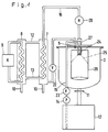
- FIG. 1 Two embodiments for the device according to the invention are shown in the drawing and are described in detail below.
- the figures show a schematic representation of a device for separating chlorinated hydrocarbons from processing oils from a solution using air.
- An oil solvent solution e.g. a solution of 70% oil and 30% trichlorethylene, swirled with a dry gas or gas mixture, which is fed to the evaporative boiler 2.
- the gas enriched with solvent is fed to a cooling device via an outlet line 6 connected to the evaporation boiler 2.
- the cooling device has a gas-gas heat exchanger 7, in which pre-cooling takes place. Downstream of the gas-gas heat exchanger 7 is a refrigerant-gas heat exchanger 8. The division of the cooling process into a pre-cooling and an after-cooling / drying significantly improves the efficiency of the device.
- the temperature in the refrigerant gas heat exchanger ranges up to approx. - 35 ° C.
- the gas which has been pre-cooled in the gas-gas heat exchanger 7 and enriched with solvent, reaches the refrigerant-gas heat exchanger 8 via a line 12.
- drying takes place by strong cooling.
- the refrigerant is brought to the desired temperature in a refrigerator 9, which is shown in the drawing as a switching block.
- the solvent thawed in the refrigerant-gas heat exchanger 8 is removed via a steam trap 10 and can be used again.
- the dried cold gas flows in countercurrent through a line 13 back into the gas-gas heat exchanger 7, where it is heated up to about 80 ° C. From there it is fed back into the evaporation boiler 2 via a feed line 16.
- a fan 22 is provided in the outlet line 6.
- the fan can also be provided in line 12.
- a heating device 20 is arranged in the feed line 16, in which the dry air is heated up to approximately 95 ° C.
- a throttling valve can be arranged between the heating device 20 and the inlet opening. The amount of gas in the circuit here is approx. 150 l.
- the oil-solvent solution is led out of a container 17 by means of a pump 14 via a line 15.
- a heater 23 for the oil-solvent solution is arranged in line 15.
- the line 15 passes through the wall or the lid of the evaporation boiler 2.
- the line 15 opens into a nozzle 24.
- the oil-solvent solution is sprayed off as a mist from the nozzle 24.
- a spray cone 25 forms with the nozzle 24 as the central point.
- the nozzle 24 is arranged in the central axis of an inner tube 26.
- the dry gas from the feed line 16 also reaches the area of the inner tube 26. The dry gas mixes intimately with the oil-solvent solution leaving the nozzle 24.
- An outlet 11 is connected to the container 17.
- the cycle is interrupted when only solvent-free oil is present in the container 17.
- the gas is guided in the flow direction with the oil-solvent solution.
- the line 15 with the oil-solvent solution passes through the lid of the evaporation boiler 2.
- the spray cone 25 opens directly onto the inner wall of the inner tube 26.
- a pipe section 27 is arranged, in which the feed line 16 for the dry gas opens.
- the gas is guided in the counterflow direction to the oil-solvent solution.
- the line 15 passes through the evaporation boiler 2 in the region of its bottom.
- the nozzle 24 is directed from below against the baffle plate 19 which is fastened to the inner tube 26 by means of a linkage 28.
- the solution sprayed from the baffle plate 19 forms the spray cone 25.
- the tube piece 27 is arranged on the side of the baffle plate 19 facing away from the nozzle 24.
- the method and the device are used to separate solvents and oils from an oil-solvent solution, in particular chlorinated or fluorinated hydrocarbons from processing oils.
Landscapes
- Chemical & Material Sciences (AREA)
- Chemical Kinetics & Catalysis (AREA)
- General Chemical & Material Sciences (AREA)
- Engineering & Computer Science (AREA)
- Materials Engineering (AREA)
- Mechanical Engineering (AREA)
- Metallurgy (AREA)
- Organic Chemistry (AREA)
- Vaporization, Distillation, Condensation, Sublimation, And Cold Traps (AREA)
- Treatment Of Liquids With Adsorbents In General (AREA)
Description
- Die Erfindung betrifft ein Verfahren zum Trennen von Lösemittel und Ölen einer Öl-Lösemittel-Lösung, bei dem die Öl-Lösemittel-Lösung in einem Verdunstungskessel mit einem trockenen Gas bzw. Gasgemisch verwirbelt wird, das mit Lösemittel angereicherte Gas abgeführt und abgekühlt, das dabei ausgetaute Lösemittel entfernt und das lösemittelfreie Öl abgelassen wird, sowie eine Vorrichtung zur Durchführung des Verfahrens.
- In vielen Bereichen der Industrie ist es unvermeidbar, daß Lösemittel, z.B. chlorierte Kohlenwasserstoffe (-CKW) oder fluorierte Kohlenwasserstoffe (-FKW), in Bearbeitungsöle gelangen. Beispiel hierfür ist die Entfernung bzw. Reinigung öliger Metallteile in CKW- oder FKW-Waschanlagen.
- Aus der DE-A-3229030 sind ein Verfahren und eine Vorrichtung zur Nachbehandlung lösungsmittelhaltiger, flüssiger, brennbarer Rückstände von Maschinen bekannt, z.B. zum Entfernen von chemischen Lösungsmitteln aus flüssigen Rückständen, die ölhaltig sein können und aus Bearbeitungsmaschinen stammen. Die Lösung aus Rückständen und Lösungsmitteln wird in einen beheizten Behälter gegeben. Aus der Umgebung angesaugte, erhitzte Luft wird im Bereich des Behälterbodens durch die Rückstände geleitet. Die erhitzte Luft nimmt dabei in den Rückständen enthaltenes Lösungsmittel auf. Die mit Lösungsmittel beladene Luft wird über einen Kondensator ins Freie geleitet. Das im Kondensator verflüssigte Lösungsmittel fließt in einen Sammelbehälter. Die nachbehandelten flüssigen Rückstände werden an der tiefsten Stelle des Bodens des Behälters abgezogen und einem Transportfaß zugeleitet in dem sie zu einer Verbrennungsanlage transportiert werden. Das bekannte Verfahren/die bekannte Vorrichtung dient also dazu, Rückstände der genannten Art so weit nachzubehandeln, daß sie einer Verbrennung zugeführt werden können. Die nachbehandelten Rückstände sind aber` nach den heutigen gesetzlichen Bestimmungen als Sondermüll zu betrachten; kostenspielige Entsorgung durch Verbrennung bleibt die Folge.
- In der älteren Patentanmeldung EP-A-0347605 entsteht als Abschluß eines Verfahrens der eingangs genannten Art lösemittelfreies Öl dadurch, daß das durch starkes Abkühlen vom Lösemittel befreite Gas erwärmt, erneut mit der Öl-Lösemittel-Lösung verwirbelt und das lösemittelfreie Öl abgelassen wird. Dabei wird die Öl-Lösemittel-Lösung entweder in einen Verdunstungskessel gefüllt, in die Lösung das trockene Gas gedrückt und mit der Lösung verwirbelt; oder in einen Verdunstungskessel gesprüht, quer zu dem dadurch entstehenden Nebel der Öl-Lösemittel-Lösung das trockene Gas geführt und mit der Lösung verwirbelt.
- Auch der Erfindung liegt die Aufgabe zugrunde, ein wirtschaftlich vertretbares Verfahren zu schaffen, mit dessen Hilfe eine Öl-Lösemittel-Lösung so zu trennen ist, daß das Öl praktisch lösemittelfrei ist, dabei aber den Weg wesentlich zu verlängern, auf dem die Lösung und das Gas einander berühren. Gemäß der Erfindung wird diese Aufgabe dadurch gelöst, daß die Öl-Lösemittel-Lösung von einer Düse als Nebel in der Form eines Sprühkegels mit der Düse als zentralem Punkt in einen Verdunstungskessel abgesprüht und das Gas bzw. Gasgemisch in Axialrichtung des Sprühkegels durch den Nebel geführt wird.
- Bei der Erfindung wird das trockene Gas in Axialrichtung zu dem Nebel der in den Verdunstungskessel gesprühten Öl-Lösemittel-Lösung geführt und mit der Lösung verwirbelt. Es ergibt sich eine wesentliche Verlängerung des Weges, auf dem die durch das Versprühen tröpfchenweise, also mit großer Oberfläche, vorliegende Lösung und das Gas einander berühren. Durch die sehr starke Verwirbelung der Öl-Lösemittel-Lösung mit trockenem Gas wird die Verdunstung des Lösemittels um ein Vielfaches beschleunigt. Das Ergebnis wird erzielt unabhängig davon, ob in einer Ausgestaltung der Erfindung das Gasgemisch in Strömungsrichtung mit der Öl-Lösemittel-Lösung geführt wird, oder in einer anderen Ausgestaltung in Gegenströmungsrichtung. In jedem Fall ist der Weg, auf dem die Teilchen sich berühren, länger als wenn das Gas quer zu der Lösung geführt würde. Das mit Lösungsmittel angereicherte Gas wird dann durch starkes Abkühlen getrocknet. Das dabei ausgetaute Lösemittel wird entfernt. Das getrocknete Gas wird abgeführt. Als Gas werden - in Abhängigkeit vom Lösemittel - beispielsweise Luft, Kohlendioxid oder Stickstoff verwendet. In Ausgestaltung der Erfindung wird das durch das starke Abkühlen getrocknete Gas erwärmt und erneut mit der Öl-Lösemittel-Lösung verwirbelt. Das Lösemittel ist einer weiteren Verwendung zuführbar; das Gas bleibt im geschlossenen Kreislauf und kann erneut verwendet werden. Das am Abschluß eines Verfahrens lösemittelfreie Öl wird abgelassen.
- In Versuchen hat sich das Verfahen nach der Erfindung bei der Trennung von chlorierten Kohlenwasserstoffen in Bearbeitungsölen bewährt. Lösemittelanteile von kleiner 0,1 % wurden ohne weiteres erreicht.
- Nach der ersten Verwirbelung von trockenem Gas und Öl-Lösemittel-Lösung in dem Verdunstungskessel ist die Lösung noch nicht in dem gewünschten Maß von dem Lösemittel frei. Die Lösung wird daher mehrfach dem Verdunstungskessel zugeführt. Nach jedem Durchlauf ist in der Lösung ein geringerer Anteil von Lösemittel.
- Zwei Arten von Vorrichtungen zur Durchführung des Verfahrens nach der Erfindung werden bevorzugt: Bei der einen Vorrichtung ist in dem Verdunstungskessel ein Prallteller angeordnet, auf den die Öl-Lösemittel-Lösung gelenkt, und von dem sie abgesprüht ist; bei der anderen Vorrichtung ist eine Düse verwendet, über die die Öl-Lösemittel-Lösung in den Verdunstungskessel gesprüht ist. In beiden Fällen wird dem Lösemittel Tröpfchenform gegeben und somit die größtmögliche Oberfläche für den Angriff des Gases erreicht.
- In Ausgestaltung sind die Vorrichtungen zur Durchführung des Verfahrens gekennzeichnet durch eine Kühleinrichtung, die für die Zuführung des mit Lösemittel angereicherten Gases mit dem Verdunstungskessel verbunden und die mit Leitungen für die Entfernung des ausgetauten Lösemittels und die Abführung des getrockneten Gases versehen ist. Mit einer solchen Vorrichtung wurden die vorgenannten Ergebnisse erzielt.
- Der Wirkungsgrad der Vorrichtung nach der Erfindung wird weiter erhöht, wenn zwischen der Auslaßöffnung an dem Verdunstungskessel für das mit Lösemittel angereicherte Gas und der Kühleinrichtung ein Ventilator und/oder in der Zuleitung in Strömungsrichtung des Gases vor dem Verdunstungskessel ein drosselbares Ventil angeordnet ist. Hierdurch wird in dem Verdunstungskessel ein Unterdruck einstellbar, der die Verdunstung des Lösemittels begünstigt, in dem Gas-Gas-Wärmetauscher ein Überdruck, der die Trennung des Lösemittels von dem Gas begünstigt.
- In weiteren Vorrichtungsansprüchen sind Ausgestaltungen und Weiterbildungen der Erfindung beschrieben.
- Zwei Ausführungsbeispiele für die Vorrichtung nach der Erfindung sind in der Zeichnung dargestellt und werden nachfolgend im einzelnen beschrieben. Die Figuren zeigen in schematischer Darstellung je eine Vorrichtung zum Trennen chlorierter Kohlenwasserstoffe von Bearbeitungsölen aus einer Lösung mit Hilfe von Luft.
- In einem Verdunstungskessel 2 wird eine Öl-Lösemittel-Lösung, z.B. eine Lösung aus 70 % Öl und 30 % Trichloräthylen, mit einem trockenen Gas oder Gasgemisch verwirbelt, das dem Verdunstungskessel 2 zugeführt wird. Das mit Lösemittel angereicherte Gas wird über eine an den Verdunstungskessel 2 angeschlossene Auslaßleitung 6 einer Kühlvorrichtung zugeführt.
- Die Kühlvorrichtung weist einen Gas-Gas-Wärmetauscher 7 auf, in dem eine Vorkühlung erfolgt. Dem Gas-Gas-Wärmetauscher 7 nachgeordnet ist ein Kältemittel-Gas-Wärmetauscher 8. Die Aufteilung des Kühlvorgangs in eine Vorkühlung und eine Nachkühlung/Trocknung verbessert den Wirkungsgrad der Vorrichtung wesentlich. Die Temperatur im Kältemittel-Gas-Wärmetauscher reicht bis ca. - 35°C.
- Das in dem Gas-Gas-Wärmetauscher 7 vorgekühlte mit Lösemittel angereicherte Gas gelangt über eine Leitung 12 in den Kältemittel-Gas-Wärmetauscher 8. In dem Wärmetauscher 8 erfolgt eine Trocknung durch starkes Abkühlen. Das Kältemittel ist in einer Kältemaschine 9, die in der Zeichnung als Schaltblock dargestellt ist, auf die gewünschte Temperatur gebracht. Das in dem Kältemittel-Gas-Wärmetauscher 8 ausgetaute Lösemittel wird über einen Kondensatableiter 10 entfernt und kann erneut verwendet werden. Das getrocknete kalte Gas gelangt im Gegenstrom über eine Leitung 13 wieder in den Gas-Gas-Wärmetauscher 7, wo es auf bis zu ca. 80°C erhitzt wird. Von dort aus wird es über eine Zuleitung 16 wieder in den Verdunstungskessel 2 geleitet.
- In der Auslaßleitung 6 ist ein Ventilator 22 vorgesehen. Der Ventilator kann auch in der Leitung 12 vorgesehen sein. In der Zuleitung 16 ist eine Heizvorrichtung 20 angeordnet, in der die Erhitzung der trockenen Luft auf bis zu ca. 95°C erfolgt. Zwischen Heizvorrichtung 20 und Einlaßöffnung kann ein drosselbares Ventil angeordnet sein. Die Gasmenge im Kreislauf beträgt hier ca. 150 l.
- Die Öl-Lösemittel-Lösung wird aus einem Behälter 17 mittels einer Pumpe 14 über eine Leitung 15 geführt. In der Leitung 15 ist eine Heizvorrichtung 23 für die Öl-Lösemittel-Lösung angeordnet. Die Leitung 15 durchsetzt die Wandung oder den Deckel des Verdunstungskessels 2. Die Leitung 15 mündet in einer Düse 24. Von der Düse 24 wird die Öl-Lösemittel-Lösung als Nebel abgesprüht. Mit der Düse 24 als zentralem Punkt bildet sich ein Sprühkegel 25. Die Düse 24 ist in der Mittelachse eines Innenrohres 26 angeordnet. Auch das trockene Gas aus der Zuleitung 16 gelangt in den Bereich des Innenrohres 26. Das trockene Gas mischt sich mit der die Düse 24 verlassenden Öl-Lösemittel-Lösung innig.
- Mit dem Behälter 17 ist ein Auslaß 11 verbunden. Abhängig von der Anreicherung der Öl-Lösemittel-Lösung mit Lösemittel und dem Wirkungsgrad des Trennvorgangs in dem Verdunstungskessel 2 wird der Kreislauf abgebrochen, wenn in dem Behälter 17 nur noch lösemittelfreies Öl vorhanden ist.
- Bei dem in Figur 1 dargestellten Ausführungsbeispiel ist das Gas in Strömungsrichtung mit der Öl-Lösemittel-Lösung geführt. Bei dieser Ausführung durchsetzt die Leitung 15 mit der Öl-Lösemittel-Lösung den Deckel des Verdunstungskessels 2. Der Sprühkegel 25 mündet direkt auf der Innenwandung des Innenrohres 26. Um den die Düse 24 einschließenden Teil der Leitung 15 ist ein Rohrstück 27 angeordnet, in dem die Zuleitung 16 für das trockene Gas mündet.
- Bei dem in Figur 2 dargestellten Ausführungsbeispiel ist das Gas in Gegenströmungsrichtung zu der Öl-Lösemittel-Lösung geführt. Die Leitung 15 durchsetzt den Verdunstungskessel 2 im Bereich seines Bodens. Die Düse 24 ist von unten gegen den Prallteller 19 gerichtet, der mittels eines Gestänges 28 an dem Innenrohr 26 befestigt ist. Die von dem Prallteller 19 absprühende Lösung bildet den Sprühkegel 25. Das Rohrstück 27 ist bei dieser Ausführung auf der der Düse 24 abgewandten Seite des Prallteller 19 angeordnet.
- Das Verfahren und die Vorrichtung dienen zur Trennung von Lösemitteln und Ölen aus einer Öl-Lösemittel-Lösung, insbesondere von chlorierten oder fluorierten Kohlenwasserstoffen aus Bearbeitungsölen.
Claims (12)
- Verfahren zum Trennen von Lösemitteln und Ölen einer Öl-Lösemittel-Lösung, bei dem die Öl-Lösemittel-Lösung in einem Verdunstungskessel (2) mit einem trockenen Gas bzw. Gasgemisch verwirbelt wird, das mit Lösemittel angereicherte Gas abgeführt und abgekühlt, das dabei ausgetaute Lösemittel entfernt und das lösemittelfreie Öl abgelassen wird, dadurch gekennzeichnet, daß die Öl-Lösemittel-Lösung von einer Düse (24) als Nebel in der Form eines Sprühkegels (25) mit der Düse (24) als zentralem Punkt abgesprüht und das Gas bzw. Gasgemisch in Axialrichtung des Sprühkegels (25) durch den Nebel geführt wird.
- Verfahren nach Anspruch 1, dadurch gekennzeichnet, daß das durch starkes Abkühlen vom Lösemittel befreite Gas erwärmt und erneut mit der Öl-Lösemittel-Lösung verwirbelt wird.
- Verfahren nach Anspruch 1 oder 2, dadurch gekennzeichnet, daß Gas- und Öl-Lösemittel-Lösungsstrom im Gleichstrom geführt werden.
- Verfahren nach Anspruch 1 oder 2, dadurch gekennzeichnet, daß Gas- und Öl-Lösemittel-Lösunsstrom im Gegenstrom geführt werden
- Vorrichtung zum Trennen von Lösemitteln und Ölen einer Öl-Lösemittel-Lösung, bei dem die Öl-Lösemittel-Lösung in einem Verdunstungskessel (2) mit einem trockenen Gas bzw. Gasgemisch verwirbelbar ist, das mit Lösemittel angereicherte Gas abführbar und abkühlbar, das dabei ausgetaute Lösemittel entfernbar und das lösemittelfreie Öl abloßbar ist, dadurch gekennzeichnet, daß die Öl-Lösemittel-Lösung von einer in dem Verdunstungskessel (2) angeordneten Düse (24) auf einen Prallteller (19) lenkbar und von diesem als Nebel in der Form eines Sprühkegels (25) mit der Düse (24) als zentralem Punkt absprühbar ist und das Gas bzw. Gasgemisch in Axialrichtung des Sprühkegels (25) durch den Nebel führbar ist.
- Vorrichtung zum Trennen von Lösemitteln und Ölen einer Öl-Lösemittel-Lösung, bei dem die Öl-Lösemittel-Lösung in einem Verdunstungskessel (2) mit einem trockenen Gas bzw. Gasgemisch verwirbelbar ist, das mit Lösemittel angereicherte Gas abführbar und abkühlbar, das dabei ausgetaute Lösemittel entfernbar und das lösemittelfreie Öl abloßbar ist, dadurch gekennzeichnet, daß die Öl-Lösemittel-Lösung von einer von einem in dem Verdunstungskessel (2) vorgesehenen Innenrohr umgebenen Düse (24) als Nebel in der Form eines Sprühkegels (25) mit der Düse (24) als zentralem Punkt absprühbar ist und das Gas bzw. Gasgemisch in Axialrichtung des Sprühkegels (25) durch den Nebel führbar ist.
- Vorrichtung nach Anspruch 6, dadurch gekennzeichnet, daß die Düse (24) von einem Rohrstück (27) umgeben ist, über das das trockene Gas dem Verdunstungskessel (2) zuführbar ist.
- Vorrichtung nach Anspruch 6 in Verbindung mit Anspruch 5, dadurch gekennzeichnet, daß der Prallteller (19), gegen den die Düse (24) gerichtet ist in dem Innenrohr (26) vorgesehen ist.
- Vorrichtung nach einem der Ansprüche 5 bis 8 gekennzeichnet durch eine Kühleinrichtung (7; 8) die für die Zuführung des mit Lösemittel angereicherten Gases mit dem Verdunstungskessel (2) verbunden und die mit Leitungen für die Entfernung des ausgetauten Lösemittels sowie die Abführung des getrockneten Gases versehen ist.
- Vorrichtung nach Anspruch 9, dadurch gekennzeichnet, daß zwischen einer Auslaßöffnung (6) an dem Verdunstungskessel (2) für das mit Lösemittel angereicherte Gas und der Kühleinrichtung (7; 8) ein Ventilator (22) angeordnet ist.
- Vorrichtung nach Anspruch 9 oder 10, dadurch gekennzeichnet, daß die Kühleinrichtung (7; 8) in einen Gas-Gas-Wärmetauscher (7) zur Vor-` kühlung und einen nachgeordneten Kältemittel-Gas-Wärmetauscher (8) zur Trocknung des mit Lösemittel angereicherten Gases geteilt ist.
- Vorrichtung nach Anspruch 11, dadurch gekennzeichnet, daß der Kältemittel-Gas-Wärmetauscher (8) mit einem Kondensatableiter (10) für das ausgetaute Lösemittel und mit einer Verbindungsleitung (12) nach dem Gas-Gas-Wärmetauscher (7) für die Erwärmung des getrockneten Gases verbunden ist, der seinerseits über eine weitere Leitung (5) für die Abgabe des erwärmten trockenen Gases mit dem Verdunstungskessel (2) verbunden ist.
Applications Claiming Priority (1)
| Application Number | Priority Date | Filing Date | Title |
|---|---|---|---|
| PCT/DE1989/000774 WO1991008812A1 (de) | 1989-12-15 | 1989-12-15 | Verfahren und vorrichtung zum trennen von lösemitteln und ölen |
Publications (2)
| Publication Number | Publication Date |
|---|---|
| EP0458789A1 EP0458789A1 (de) | 1991-12-04 |
| EP0458789B1 true EP0458789B1 (de) | 1994-02-23 |
Family
ID=6835351
Family Applications (1)
| Application Number | Title | Priority Date | Filing Date |
|---|---|---|---|
| EP90900752A Expired - Lifetime EP0458789B1 (de) | 1989-12-15 | 1989-12-15 | Verfahren und vorrichtung zum trennen von lösemitteln und ölen |
Country Status (4)
| Country | Link |
|---|---|
| EP (1) | EP0458789B1 (de) |
| AT (1) | ATE101800T1 (de) |
| DE (1) | DE58907046D1 (de) |
| WO (1) | WO1991008812A1 (de) |
Families Citing this family (2)
| Publication number | Priority date | Publication date | Assignee | Title |
|---|---|---|---|---|
| DE19736281A1 (de) * | 1997-08-21 | 1999-02-25 | Hopf Karl Heinz | Verfahren sowie Anlage zur thermischen Trennung einer Wasser-/Ölemulsion |
| EP1240929A1 (de) * | 2001-03-13 | 2002-09-18 | Eugène Deckers | Lösungsmittelregeneration durch Destillation |
Family Cites Families (6)
| Publication number | Priority date | Publication date | Assignee | Title |
|---|---|---|---|---|
| DE348332C (de) * | 1917-04-13 | 1922-02-04 | G A Krause & Co Akt Ges | Verfahren und Vorrichtung zum Eindampfen oder Eindicken von Fluessigkeiten |
| NL103486C (de) * | 1940-11-05 | |||
| DE3071792D1 (en) * | 1979-12-03 | 1986-11-13 | Francois Caillierez | Apparatus for the regeneration of spent solvents and use of the said apparatus |
| DE3145815C2 (de) * | 1981-11-19 | 1984-08-09 | AGA Gas GmbH, 2102 Hamburg | Verfahren zum Entfernen von ablösungsfähigen Materialschichten von beschichteten Gegenständen, |
| DE3229030A1 (de) * | 1982-08-04 | 1984-02-09 | Fluormatic GmbH, 7407 Rottenburg | Verfahren und vorrichtung zur nachbehandlung loesungsmittelhaltiger, fluessiger, brennbarer rueckstaende von maschinen |
| JPS59209601A (ja) * | 1983-05-16 | 1984-11-28 | Kuri Kagaku Sochi Kk | 不活性ガスを用いる蒸発蒸溜装置 |
-
1989
- 1989-12-15 DE DE90900752T patent/DE58907046D1/de not_active Expired - Fee Related
- 1989-12-15 WO PCT/DE1989/000774 patent/WO1991008812A1/de not_active Ceased
- 1989-12-15 AT AT90900752T patent/ATE101800T1/de not_active IP Right Cessation
- 1989-12-15 EP EP90900752A patent/EP0458789B1/de not_active Expired - Lifetime
Also Published As
| Publication number | Publication date |
|---|---|
| EP0458789A1 (de) | 1991-12-04 |
| WO1991008812A1 (de) | 1991-06-27 |
| ATE101800T1 (de) | 1994-03-15 |
| DE58907046D1 (de) | 1994-03-31 |
Similar Documents
| Publication | Publication Date | Title |
|---|---|---|
| DE19629500C1 (de) | Multiwäscher und Verfahren zur Totalreinigung von Gasen | |
| EP2001571A1 (de) | Verfahren zur abtrennung leichtflüchtiger komponenten aus einem stoffgemisch sowie vorrichtung zur durchführung dieses verfahrens | |
| DE69313625T2 (de) | Verfahren und vorrichtung zur behandlung von gasströmen | |
| DE2405669A1 (de) | Vorrichtung zum reinigen von abgas oder abluft | |
| EP1901017A1 (de) | Verfahren und Anlage zum Trocknen von Gegenständen | |
| EP0800851A1 (de) | Vorrichtung zur Reinigung schadstoffbelasteter Abluft | |
| EP0203259B1 (de) | Verfahren zur Regenerierung eines beladenen Waschmittels | |
| DE2614587A1 (de) | Verfahren zum eindampfen wasserhaltiger fluessigkeiten | |
| DE69617808T2 (de) | Wäscher für Gas- und Dampfströme aus Industrieprozessen | |
| EP0347605B1 (de) | Verfahren und Vorrichtung zum Trennen von Lösemitteln und Ölen | |
| DE19601759A1 (de) | Anlage zum Abscheiden von Schadstoffen aus der Abluft einer Schadstoffquelle, insbesondere eines Spannrahmens | |
| EP2477725B1 (de) | Verfahren zum trocknen von erdgas durch gemeinsame kühlung von lösungsmittel und erdgas | |
| DE2928392A1 (de) | Vorrichtung zur meerwasserentsalzung durch bruedenkompression | |
| EP0458789A1 (de) | Verfahren und vorrichtung zum trennen von lösemitteln und ölen. | |
| WO1990000437A1 (de) | Verfahren und vorrichtung zum reinigen von abgasen | |
| DE3229030A1 (de) | Verfahren und vorrichtung zur nachbehandlung loesungsmittelhaltiger, fluessiger, brennbarer rueckstaende von maschinen | |
| DE3431829A1 (de) | Vorrichtung zum reinigen, insbesondere entschwefeln, von rauchgasen aller art | |
| DE3106873A1 (de) | Verfahren zur nutzung der bei eindickprozessen von fluessigkeiten entstehenden brueden | |
| DE69501844T2 (de) | Behandlung von Fluiden, insbesondere das Reinigen von umweltschädlichen Emissionen, und Vorrichtung zu dessen Durchführung | |
| DE10024124C1 (de) | Vorrichtung zur Trennung von Flüssigkeiten mit unterschiedlichen Siedepunkten, insbesondere zur Abscheidung von Wasser aus Öl | |
| EP0571408B1 (de) | Verfahren und vorrichtung zum reinigen von mit schadstoffen beladenen gasen | |
| DE4440629C1 (de) | Vorrichtung zur Abscheidung und Zerstörung von Schäumen bei der Verdampfung von Flüssigkeitsgemischen | |
| EP2025382B1 (de) | Verfahren und vorrichtung zur behandlung von produkten mit einem gasstrom | |
| DE2721221C3 (de) | Vorrichtung zum Erwarmen von pumpbaren Substanzen | |
| DE29918054U1 (de) | Vorrichtung zur Brennkammerreinigung |
Legal Events
| Date | Code | Title | Description |
|---|---|---|---|
| PUAI | Public reference made under article 153(3) epc to a published international application that has entered the european phase |
Free format text: ORIGINAL CODE: 0009012 |
|
| AK | Designated contracting states |
Kind code of ref document: A1 Designated state(s): AT BE CH DE FR GB IT LI LU NL SE |
|
| 17P | Request for examination filed |
Effective date: 19911104 |
|
| 17Q | First examination report despatched |
Effective date: 19921015 |
|
| GRAA | (expected) grant |
Free format text: ORIGINAL CODE: 0009210 |
|
| AK | Designated contracting states |
Kind code of ref document: B1 Designated state(s): AT BE CH DE FR GB IT LI LU NL SE |
|
| PG25 | Lapsed in a contracting state [announced via postgrant information from national office to epo] |
Ref country code: IT Free format text: LAPSE BECAUSE OF FAILURE TO SUBMIT A TRANSLATION OF THE DESCRIPTION OR TO PAY THE FEE WITHIN THE PRE;WARNING: LAPSES OF ITALIAN PATENTS WITH EFFECTIVE DATE BEFORE 2007 MAY HAVE OCCURRED AT ANY TIME BEFORE 2007. THE CORRECT EFFECTIVE DATE MAY BE DIFFERENT FROM THE ONE RECORDED.SCRIBED TIME-LIMIT Effective date: 19940223 Ref country code: NL Effective date: 19940223 Ref country code: BE Effective date: 19940223 Ref country code: SE Effective date: 19940223 |
|
| REF | Corresponds to: |
Ref document number: 101800 Country of ref document: AT Date of ref document: 19940315 Kind code of ref document: T |
|
| ET | Fr: translation filed | ||
| GBT | Gb: translation of ep patent filed (gb section 77(6)(a)/1977) |
Effective date: 19940222 |
|
| REF | Corresponds to: |
Ref document number: 58907046 Country of ref document: DE Date of ref document: 19940331 |
|
| NLV1 | Nl: lapsed or annulled due to failure to fulfill the requirements of art. 29p and 29m of the patents act | ||
| PLBE | No opposition filed within time limit |
Free format text: ORIGINAL CODE: 0009261 |
|
| STAA | Information on the status of an ep patent application or granted ep patent |
Free format text: STATUS: NO OPPOSITION FILED WITHIN TIME LIMIT |
|
| PG25 | Lapsed in a contracting state [announced via postgrant information from national office to epo] |
Ref country code: LU Free format text: LAPSE BECAUSE OF NON-PAYMENT OF DUE FEES Effective date: 19941231 |
|
| 26N | No opposition filed | ||
| PGFP | Annual fee paid to national office [announced via postgrant information from national office to epo] |
Ref country code: GB Payment date: 19971204 Year of fee payment: 9 |
|
| PGFP | Annual fee paid to national office [announced via postgrant information from national office to epo] |
Ref country code: AT Payment date: 19971217 Year of fee payment: 9 |
|
| PGFP | Annual fee paid to national office [announced via postgrant information from national office to epo] |
Ref country code: FR Payment date: 19971229 Year of fee payment: 9 |
|
| PGFP | Annual fee paid to national office [announced via postgrant information from national office to epo] |
Ref country code: CH Payment date: 19980109 Year of fee payment: 9 |
|
| PG25 | Lapsed in a contracting state [announced via postgrant information from national office to epo] |
Ref country code: AT Free format text: LAPSE BECAUSE OF NON-PAYMENT OF DUE FEES Effective date: 19981215 Ref country code: GB Free format text: LAPSE BECAUSE OF NON-PAYMENT OF DUE FEES Effective date: 19981215 |
|
| PG25 | Lapsed in a contracting state [announced via postgrant information from national office to epo] |
Ref country code: LI Free format text: LAPSE BECAUSE OF NON-PAYMENT OF DUE FEES Effective date: 19981231 Ref country code: CH Free format text: LAPSE BECAUSE OF NON-PAYMENT OF DUE FEES Effective date: 19981231 |
|
| GBPC | Gb: european patent ceased through non-payment of renewal fee |
Effective date: 19981215 |
|
| REG | Reference to a national code |
Ref country code: CH Ref legal event code: PL |
|
| PG25 | Lapsed in a contracting state [announced via postgrant information from national office to epo] |
Ref country code: FR Free format text: LAPSE BECAUSE OF NON-PAYMENT OF DUE FEES Effective date: 19990831 |
|
| REG | Reference to a national code |
Ref country code: FR Ref legal event code: ST |
|
| PGFP | Annual fee paid to national office [announced via postgrant information from national office to epo] |
Ref country code: DE Payment date: 20010205 Year of fee payment: 12 |
|
| PG25 | Lapsed in a contracting state [announced via postgrant information from national office to epo] |
Ref country code: DE Free format text: LAPSE BECAUSE OF NON-PAYMENT OF DUE FEES Effective date: 20020702 |