EP0458685A1 - Process and device for the spraying of liquid, as well as their applications - Google Patents
Process and device for the spraying of liquid, as well as their applications Download PDFInfo
- Publication number
- EP0458685A1 EP0458685A1 EP91401281A EP91401281A EP0458685A1 EP 0458685 A1 EP0458685 A1 EP 0458685A1 EP 91401281 A EP91401281 A EP 91401281A EP 91401281 A EP91401281 A EP 91401281A EP 0458685 A1 EP0458685 A1 EP 0458685A1
- Authority
- EP
- European Patent Office
- Prior art keywords
- liquid
- gas
- flow
- annular
- channel
- Prior art date
- Legal status (The legal status is an assumption and is not a legal conclusion. Google has not performed a legal analysis and makes no representation as to the accuracy of the status listed.)
- Granted
Links
Images
Classifications
-
- B—PERFORMING OPERATIONS; TRANSPORTING
- B05—SPRAYING OR ATOMISING IN GENERAL; APPLYING FLUENT MATERIALS TO SURFACES, IN GENERAL
- B05B—SPRAYING APPARATUS; ATOMISING APPARATUS; NOZZLES
- B05B7/00—Spraying apparatus for discharge of liquids or other fluent materials from two or more sources, e.g. of liquid and air, of powder and gas
- B05B7/02—Spray pistols; Apparatus for discharge
- B05B7/04—Spray pistols; Apparatus for discharge with arrangements for mixing liquids or other fluent materials before discharge
-
- B—PERFORMING OPERATIONS; TRANSPORTING
- B05—SPRAYING OR ATOMISING IN GENERAL; APPLYING FLUENT MATERIALS TO SURFACES, IN GENERAL
- B05B—SPRAYING APPARATUS; ATOMISING APPARATUS; NOZZLES
- B05B7/00—Spraying apparatus for discharge of liquids or other fluent materials from two or more sources, e.g. of liquid and air, of powder and gas
- B05B7/02—Spray pistols; Apparatus for discharge
- B05B7/06—Spray pistols; Apparatus for discharge with at least one outlet orifice surrounding another approximately in the same plane
- B05B7/062—Spray pistols; Apparatus for discharge with at least one outlet orifice surrounding another approximately in the same plane with only one liquid outlet and at least one gas outlet
- B05B7/065—Spray pistols; Apparatus for discharge with at least one outlet orifice surrounding another approximately in the same plane with only one liquid outlet and at least one gas outlet an inner gas outlet being surrounded by an annular adjacent liquid outlet
-
- F—MECHANICAL ENGINEERING; LIGHTING; HEATING; WEAPONS; BLASTING
- F23—COMBUSTION APPARATUS; COMBUSTION PROCESSES
- F23D—BURNERS
- F23D11/00—Burners using a direct spraying action of liquid droplets or vaporised liquid into the combustion space
- F23D11/10—Burners using a direct spraying action of liquid droplets or vaporised liquid into the combustion space the spraying being induced by a gaseous medium, e.g. water vapour
- F23D11/106—Burners using a direct spraying action of liquid droplets or vaporised liquid into the combustion space the spraying being induced by a gaseous medium, e.g. water vapour medium and fuel meeting at the burner outlet
-
- F—MECHANICAL ENGINEERING; LIGHTING; HEATING; WEAPONS; BLASTING
- F23—COMBUSTION APPARATUS; COMBUSTION PROCESSES
- F23D—BURNERS
- F23D11/00—Burners using a direct spraying action of liquid droplets or vaporised liquid into the combustion space
- F23D11/10—Burners using a direct spraying action of liquid droplets or vaporised liquid into the combustion space the spraying being induced by a gaseous medium, e.g. water vapour
- F23D11/12—Burners using a direct spraying action of liquid droplets or vaporised liquid into the combustion space the spraying being induced by a gaseous medium, e.g. water vapour characterised by the shape or arrangement of the outlets from the nozzle
- F23D11/14—Burners using a direct spraying action of liquid droplets or vaporised liquid into the combustion space the spraying being induced by a gaseous medium, e.g. water vapour characterised by the shape or arrangement of the outlets from the nozzle with a single outlet, e.g. slit
Definitions
- the present invention relates to a method and a device for spraying liquid.
- the invention also relates to various applications of this method and of this device.
- the method and the device according to the invention have been particularly studied for spraying fuels with a view to their combustion, but, obviously, they can be used for spraying liquids for other applications.
- the Applicant has found a way to spray viscous fuels at higher viscosities than those generally used and therefore at lower temperatures, by developing, in the spraying device, a film of viscous fluid, which is then sprayed in fine droplets using two streams of gaseous fluids.
- GB-A-2 161 915 describes a burner operating with an excess of air, under low gas pressures.
- the gas / liquid mass ratio must be very high, often of the order of 2, for the spraying to be correct.
- the gas velocities used are of the order of 100 to 150 m / s.
- the object of the present invention is therefore the spraying of liquids, with a view, in particular, to their combustion.
- the main characteristic of the process according to the invention is therefore that the mass ratio of the gas or gases with respect to the liquid is less than 0.5.
- the speed of the gas (es) should be as high as possible. It is advantageous if the speeds of the primary and secondary gas flows are sonic at the height of the edge.
- the gas can be air, water vapor, refinery gas, in the case of the combustion of fuel oil, or water vapor, in the case of the prior spraying of said fuel oil.
- the primary gas and the secondary gas are identical, these preferably come from one and the same main source, from which the flows of primary gas and secondary gas are then separated .
- the various annular channels are produced by an assembly of parts nested one inside the other as will be seen below in the description of the figures.
- the sprayer 1 shown in the drawings and intended to equip an oven for the combustion of a heavy fuel, is incorporated in an external body 2 of cylindrical section, integral with a rod, not shown, fixing the whole to the wall of the oven.
- All the parts of the injector are parts of revolution around the axis A-A ′.
- the combination of the body 4, distributors 5 and 6 and the nozzle 7, constitutes the water vapor distributor.
- the tube 3 is, as has been said previously, the main tube for supplying water vapor to the sprayer, via the internal cylindrical channel 9 of the tube 3, connected to a source of steam not shown.
- the external wall 10 of the tube 3 and the internal wall 11 of the external body 2 constitute an annular channel 12 for supplying heavy fuel oil, connected to a source of heavy fuel not shown.
- the channel 9 supplies water vapor to a cylindrical central internal chamber 13, arranged in the central body 4.
- cylindrical channels 14 In the central body 4 are provided cylindrical channels 14, the inputs 16 of which are arranged at the entrance to the chamber 13 and the outputs of which 17 open into an annular chamber 18 arranged in the distributor 5.
- the channels 14 not visible on the sections have not been shown in broken lines, as is customary.
- central body 4 In the central body 4 are also provided cylindrical channels 19, the inlets 20 of which are arranged at the downstream end of the chamber 13 and the outlets 21 of which open into inlets 22 of corresponding cylindrical channels 23, arranged in the distributor 6, via a groove 21 'forming an annular distribution channel.
- annular channel 23 ′ formed by a portion of the internal wall of the end piece 7 and of the internal wall 32 'of the distributor 6 forming the edge with the external wall 32 of said distributor.
- central body 4 In the central body 4 are further arranged cylindrical channels 24, only two of which have been shown for the sake of clarity, the inlets 25 of which are located at the end of the channel 12 and the outlets 26 of which open into an annular channel 27 .
- the walls of this channel are constituted by a bevelled portion 28 of the body 4 and by a portion of the internal wall 29 of the distributor 5
- the channel 27 is extended by an annular channel 30, the walls of which are constituted by a portion of the internal wall 31 of the external body 2 and a portion of the external wall 32 of the distributor 6, which constitutes the edge on which the liquid prefilm, which can be smooth or serrated.
- the channel 30 is extended by a circular channel 33 in the form of a ring and possibly of a venturi, the walls of which consist of a portion 34 of the internal wall of the external body 2 and a portion 35 of the external wall of the end piece 7
- a circular channel 33 in the form of a ring and possibly of a venturi, the walls of which consist of a portion 34 of the internal wall of the external body 2 and a portion 35 of the external wall of the end piece 7
- the channel 33 is in the form of venturi, part of the kinetic energy of the gas is transformed into pressure.
- the injector will be able to operate at low pressure levels.
- the annular chamber 18 is connected to the channel 30 by cylindrical channels 36, arranged in the distributor 5 and extended by an annular channel 38, constituted by a portion 37 of the exterior wall of the distributor 5 and a portion 39 of the interior wall of the body. external 2.
- the sprayer is mounted as follows.
- the distributor 5 is slid into the external body 2, the central body 4 is engaged in the external body, its end 40 passing through the distributor 5, which is pressed against the hollowed-out end 41 of the external body 2.
- the distributor 6 and the end piece 7 are threaded onto the end 40 of the body 2 and the screw 8 is screwed into the thread 42 of the body 4.
- the sprayer is then slid onto the tube 3 supplying it with steam, then connected to the fuel supply.
- the heavy fuel is brought through the annular channel 12, the cylindrical channels 24, the annular channel 27 to the annular channel 30.
- the flow of heavy fuel oil is pressed against the external wall 32 of the distributor 6 by an external peripheral flow of water vapor.
- This external peripheral flow comes from a main water vapor flow, brought by the internal channel 9, a part of which penetrates into the inlets 16 is conducted by the cylindrical channels 14 in the annular chamber 18 then in the cylindrical channels 36 and the annular channel 38.
- the fuel film formed by the action of the flow of primary peripheral water vapor internally receives a flow of secondary peripheral water vapor. This comes from chamber 13, via inputs 20, channels 19 and 23.
- Heavy fuel is thus finely divided in the canal annular 33 and sprayed into fine droplets at the outlet thereof.
- the spraying test is carried out using an oil having a density, at 15 ° C, of 850 kg / m3 (measured according to the AFNOR NFT 60-101 standard) and a viscosity of 300 mm2 / s, at 20 ° C, (measured according to AFNOR NFT 60-100 standard).
- This oil was chosen because of its high viscosity at 20 ° C, representative of that of a viscous fuel at higher temperature. It is in fact preferable to carry out the test at 20 ° C. for reasons of safety and ease of measurement.
- the diameter of the droplets at the outlet of the sprayer using a laser granulometer.
- the oil flow rate is 200 kg / h and the pressure is 6.105 pascals.
- nitrogen is used at a mass rate of 0.2 with respect to the oil, the nitrogen pressure being 6.105 pascals.
- the average diameter of the droplets obtained is 85 thousandths of mm.
- the fuel oil temperature is 120 ° C (its viscosity is then 330 mm2 / s) and its pressure is 5.105 pascals, the flow rate being 150 kg / h.
- water vapor is used as an auxiliary fluid at a mass ratio of 0.2 relative to the fuel, the pressure of the water vapor being 5.5 ⁇ 105 pascals.
- the diameter of the droplets at the outlet of the sprayer is measured using a laser granulometer.
- the oil flow rate is 600 kg / h and the pressure is 5.6.105 pascals.
- nitrogen is used as an auxiliary fluid at a mass ratio of 0.07 relative to the oil, the nitrogen pressure being 5.105 pascals.
- the average diameter of the droplets obtained is 100 thousandths of a mm.
Abstract
Description
La présente invention concerne un procédé et un dispositif de pulvérisation de liquide. L'invention concerne également diverses applications de ce procédé et de ce dispositif.The present invention relates to a method and a device for spraying liquid. The invention also relates to various applications of this method and of this device.
Le procédé et le dispositif selon l'invention ont été particulièrement étudiés pour la pulvérisation de combustibles en vue de leur combustion, mais, bien évidemment, ils peuvent être utilisés pour la pulvérisation de liquides en vue d'autres applications.The method and the device according to the invention have been particularly studied for spraying fuels with a view to their combustion, but, obviously, they can be used for spraying liquids for other applications.
Il sera fait référence ci-après, pour situer le problème posé, à la combustion de produits provenant du raffinage du pétrole brut, mais la solution apportée par l'invention peut être appliquée pour résoudre des problèmes équivalents, comme il le sera expliqué dans la suite de la présente description.Reference will be made below, to locate the problem posed, to the combustion of products from the refining of crude oil, but the solution provided by the invention can be applied to solve equivalent problems, as will be explained in following this description.
Le raffinage du pétrole brut produit, à l'heure actuelle, des produits lourds, de plus en plus visqueux, provenant d'unités de conversion.The refining of crude oil currently produces heavy, increasingly viscous products from conversion units.
Pour obtenir une bonne combustion de ces produits lourds, il est nécessaire qu'ils soient pulvérisés en fines gouttelettes, dont le diamètre soit assez petit, de l'ordre de 100 millièmes de nm. On estime que, pour obtenir cette taille de gouttelettes, il est nécessaire que la viscosité du produit soit ramenée à moins de 20 mm²/s, à la température de formation des gouttelettes. Pour des produits dont la viscosité à 100°C est de 10⁶ mm²/s, il est nécessaire d'employer des températures de pulvérisation de 270°C à 300°C, de façon à ramener la viscosité du produit à environ 20 mm²/s et à réaliser une bonne pulvérisation par les moyens de pulvérisation habituels.To obtain good combustion of these heavy products, it is necessary that they be sprayed into fine droplets, the diameter of which is quite small, of the order of 100 thousandths of a nm. It is estimated that, to obtain this droplet size, it is necessary that the viscosity of the product be reduced to less than 20 mm² / s, at the temperature of droplet formation. For products with a viscosity at 100 ° C of 10⁶ mm² / s, it is necessary to use spray temperatures from 270 ° C to 300 ° C, so as to reduce the viscosity of the product to around 20 mm² / s and to carry out a good spraying by the usual spraying means.
Si l'on ne veut pas avoir recours à des températures trop élevées, on est obligé de fluxer (diluer) les produits lourds visqueux en partie par des distillats moyens, dont l'industrie du raffinage est déficitaire, et donc d'augmenter la production de fuels lourds, dont le raffinage est excédentaire.If one does not want to use too high temperatures, one is forced to flux (dilute) the viscous heavy products in part by middle distillates, of which the refining industry is in deficit, and therefore to increase production heavy fuel oil, including refining is surplus.
Si on essaie d'utiliser les procédés habituels de pulvérisation à des températures plus faibles sans fluxer le combustible, on est amené à employer ce combustible à des viscosités plus élevées. Les procédés habituels utilisés dans ce but présentent les inconvénients de mise en oeuvre suivants :
- la pulvérisation mécanique nécessite alors des pressions élevées, de l'ordre de 2.10⁷ pascals, à 200°C, pour un produit d'une viscosité de 400 mm²/s à 200°C ;
- la pulvérisation assistée à la vapeur d'eau n'est alors pas économique, en raison des taux de vapeur nécessaires élevés (au-delà de 80 %) ;
- la pulvérisation à l'aide de brûleurs à coupelle rotative est possible (on peut se reporter pour plis de détails à l'ouvrage de A. GUILLERMIC, "Le chauffage par les combustibles liquides", Editions TECHNIP,
Tome 3, page 269), mais ces brûleurs ont l'inconvénient de nécessiter des réglages délicats et un entretien particulier du fait de l'existence de pièces en mouvement.
- mechanical spraying then requires high pressures, of the order of 2.10⁷ pascals, at 200 ° C, for a product with a viscosity of 400 mm² / s at 200 ° C;
- assisted spraying with water vapor is therefore not economical, due to the high vapor rates required (above 80%);
- spraying using rotary cup burners is possible (refer to the work by A. GUILLERMIC, "Heating by liquid fuels", Editions TECHNIP,
Volume 3, page 269 for more details), but these burners have the disadvantage of requiring delicate adjustments and special maintenance due to the existence of moving parts.
La Demanderesse a trouvé le moyen de pulvériser des combustibles visqueux à des viscosités plus élevées que celles généralement mises en oeuvre et donc à des températures plus faibles, en élaborant, dans le dispositif de pulvérisation, un film de fluide visqueux, qui est ensuite pulvérisé en fines gouttelettes à l'aide de deux flux de fluides gazeux.The Applicant has found a way to spray viscous fuels at higher viscosities than those generally used and therefore at lower temperatures, by developing, in the spraying device, a film of viscous fluid, which is then sprayed in fine droplets using two streams of gaseous fluids.
Cette technique, dite d'injection avec formation de préfilm, est déjà connue. On peut citer par exemple :
- la pulvérisation de combustible dans les turbines à gaz (voir "The development of an air blast atomizer for gas turbine application", par A.H. LEFEBVRE. et D. MILLER. Granfield College of Aeronautics, Report n° 193, juin 1966, ou "Influence of liquid properties on airblast atomizer spray characteristics", pair A.A. RIZKALLA et A.H. LEFEBVRE, Journal of Engineering for Power, Avril 1975, pages 173 à 179 ;
- la pulvérisation de mélanges charbon-eau (voir "A new burner design for CWS combustion", par S.K. BATRA et W.A. WALSH Jr., Fifth International Symposium on Coal Slurry Combustion and Technology, 25-27 Avril 1983, TAMPA, Floride.
- fuel spraying in gas turbines (see "The development of an air blast atomizer for gas turbine application", by AH LEFEBVRE. and D. MILLER. Granfield College of Aeronautics, Report n ° 193, June 1966, or "Influence of liquid properties on airblast atomizer spray characteristics ", pair AA RIZKALLA and AH LEFEBVRE, Journal of Engineering for Power, April 1975, pages 173 to 179;
- spraying coal-water mixtures (see "A new burner design for CWS combustion ", by SK BATRA and WA WALSH Jr., Fifth International Symposium on Coal Slurry Combustion and Technology, April 25-27, 1983, TAMPA, Florida.
Par ailleurs, GB-A-2 161 915 décrit un brûleur fonctionnant avec un excès d'air, sous de faibles pressions de gaz.Furthermore, GB-A-2 161 915 describes a burner operating with an excess of air, under low gas pressures.
Cependant, dans tous ces dispositifs connus, qui sont des dispositifs de combustion où le fluide gazeux est donc de l'air, le rapport massique gaz/liquide doit être très élevé, souvent de l'ordre de 2, pour que la pulvérisation soit correcte. Les vitesses de gaz utilisées sont de l'ordre de 100 à 150 m/s.However, in all these known devices, which are combustion devices where the gaseous fluid is therefore air, the gas / liquid mass ratio must be very high, often of the order of 2, for the spraying to be correct. . The gas velocities used are of the order of 100 to 150 m / s.
De tels débits de gaz sont inconcevables, quand il s'agit, comme c'est le cas dans les raffineries, de pulvériser à l'aide de vapeur d'eau sous pression un fuel de viscosité élevée.Such gas flows are inconceivable, when it is a question, as is the case in refineries, of spraying with pressurized steam a fuel of high viscosity.
En effet, même si on a à sa disposition, dans les raffineries, de la vapeur d'eau sous pression, il n'est pas économique d'employer de tels taux de vapeur.In fact, even if pressurized steam is available in refineries, it is not economical to use such steam rates.
En outre, la Demanderesse a constate que, si l'on peut abaisser le taux de vapeur à des valeurs très inférieures à celles habituellement citées, tout en conservant une bonne qualité de pulvérisation, il est alors nécessaire d'utiliser des vitesses de vapeur élevées, pour obtenir une bonne pulvérisation, impossible à réaliser avec les dispositifs précedemment connus, utilisant des vitesses de gaz relativement faibles.In addition, the Applicant has noted that, if it is possible to lower the vapor rate to values much lower than those usually cited, while maintaining good spray quality, it is then necessary to use high vapor velocities , to obtain good spraying, impossible to achieve with the previously known devices, using relatively low gas speeds.
Le but de la présente invention est donc la pulvérisation de liquides, en vue, notamment, de leur combustion.The object of the present invention is therefore the spraying of liquids, with a view, in particular, to their combustion.
A cet effet, l'invention a pour objet un procédé de pulvérisation d'un liquide à l'aide d'au moins un fluide auxiliaire tel qu'un gaz, ce procédé comprenant la mise en oeuvre :
- d'un flux annulaire dudit liquide,
- d'un flux annulaire d'un gaz primaire,
- d'un flux annulaire d'un gaz secondaire, identique ou non au précédent,
- a) à conduire le flux de liquide à l'intérieur dudit flux de gaz primaire dans le sens d'écoulement de celui-ci,
- b) à réaliser un film mince annulaire de liquide, en conduisant les flux coaxiaux de liquide et de gaz primaire sur la périphérie d'un anneau dont l'une des extrémités libres est conformée en forme d'arête,
- c) à pulvériser le liquide à l'extrémité de ladite arête par l'action combinée dudit flux de gaz primaire et du flux de gaz secondaire s'écoulant à l'intérieur de l'anneau dans le même sens que ledit flux de liquide et ledit flux de gaz primaire,
ce procédé étant caractérisé en ce que le rapport de la masse totale de gaz par rapport à la masse totale liquide est inférieur à 0,5.
- an annular flow of said liquid,
- an annular flow of a primary gas,
- an annular flow of an identical secondary gas or not to the previous one,
- a) directing the flow of liquid inside said flow of primary gas in the direction of flow thereof,
- b) producing an annular thin film of liquid, by conducting the coaxial flows of liquid and primary gas on the periphery of a ring, one of the free ends of which is shaped like an edge,
- c) spraying the liquid at the end of said edge by the combined action of said primary gas flow and the secondary gas flow flowing inside the ring in the same direction as said liquid flow and said primary gas flow,
this process being characterized in that the ratio of the total mass of gas to the total liquid mass is less than 0.5.
L'invention a aussi pour objet un dispositif de pulvérisation d'un flux de liquide à l'aide d'au moins un fluide auxiliaire tel qu'un gaz, pour la mise en oeuvre du procédé ci-dessus, par réalisation :
- d'un flux annulaire dudit liquide,
- d'un flux annulaire d'un gaz primaire,
- d'un flux annulaire d'un gaz secondaire, identique ou non au précédent,
- a) au moins un conduit d'amenée dudit liquide dans un premier canal annulaire de liquide,
- b) au moins un conduit d'amenée dudit gaz primaire dans un second canal annulaire de gaz primaire,
- c) au moins un conduit (19) d'amenée dudit gaz secondaire dans un troisième canal annulaire de gaz secondaire, les sorties des canaux annulaires étant disposées de l'extérieur vers l'intérieur du dispositif de telle façon que la sortie du premier canal et la sortie du second canal débouchent conjointement dans un quatrième canal annulaire, qui conduit le mélange de liquide et de gaz primaire à la sortie du troisième canal, le mélange de liquide et des gaz primaire et secondaire étant conduit à l'extérieur du dispositif par un cinquième canal annulaire formant éventuellement un venturi, la paroi interne du quatrième canal annulaire étant conformée en forme d'arête.
- an annular flow of said liquid,
- an annular flow of a primary gas,
- an annular flow of a secondary gas, identical or not to the previous one,
- a) at least one conduit for supplying said liquid into a first annular liquid channel,
- b) at least one conduit for supplying said primary gas into a second annular primary gas channel,
- c) at least one duct (19) for supplying said secondary gas into a third annular secondary gas channel, the outlets of the annular channels being arranged from the outside towards the inside of the device so that the outlet of the first channel and the outlet of the second channel lead jointly into a fourth annular channel, which leads the mixture of liquid and primary gas to the outlet of the third channel, the mixture of liquid and primary and secondary gases being led outside the device by a fifth annular channel possibly forming a venturi, the internal wall of the fourth annular channel being shaped as an edge.
La caractéristique principale du procédé selon l'invention est donc que le rapport massique du ou des gaz par rapport au liquide est inférieur à 0,5.The main characteristic of the process according to the invention is therefore that the mass ratio of the gas or gases with respect to the liquid is less than 0.5.
La vitesse du ou des gaz doit être la plus élevée possible. Il y a avantage à ce que les vitesses des flux de gaz primaire et secondaire soient soniques à la hauteur de l'arête.The speed of the gas (es) should be as high as possible. It is advantageous if the speeds of the primary and secondary gas flows are sonic at the height of the edge.
Le gaz peut être de l'air, de la vapeur d'eau, du gaz de raffinerie, dans le cas de la combustion du fuel, ou de la vapeur d'eau, dans le cas de la pulvérisation préalable dudit fuel.The gas can be air, water vapor, refinery gas, in the case of the combustion of fuel oil, or water vapor, in the case of the prior spraying of said fuel oil.
Dans le dispositif selon l'invention, quand le gaz primaire et le gaz secondaire sont identiques, ceux-ci proviennent de préférence d'une seul et même source principale, à partir de laquelle les flux de gaz primaire et de gaz secondaire sont ensuite séparés.In the device according to the invention, when the primary gas and the secondary gas are identical, these preferably come from one and the same main source, from which the flows of primary gas and secondary gas are then separated .
Pour des raisons de réalisation technique, les différents canaux annulaires sont réalisés par un assemblage de pièces emboîtées les unes dans les autres comme on le verra ci-après dans la description des figures.For reasons of technical implementation, the various annular channels are produced by an assembly of parts nested one inside the other as will be seen below in the description of the figures.
Les dessins annexés, qui n'ont pas de caractère limitatif, sont destinés à illustrer l'invention. Sur ces dessins :
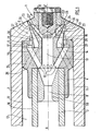
- La figure 1 est une coupe longitudinale d'un pulvérisateur selon l'invention, destiné à la combustion d'un combustible lourd ;
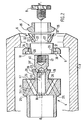
- La figure 2 est une vue éclatée, en coupe, de différentes pièces du pulvérisateur de la figure 1, représentées telles qu'elles sont adaptées les unes dans les autres selon l'axe A-A′ de la figure 1, lors du montage du pulvérisateur, à l'exception, dans un but de simplification, du
tube 3, dont il sera fait mention plus loin.
- Figure 1 is a longitudinal section of a sprayer according to the invention, for the combustion of a heavy fuel;
- FIG. 2 is an exploded view, in section, of different parts of the sprayer of FIG. 1, shown as they are adapted one inside the other along the axis AA ′ of FIG. 1, during assembly of the sprayer, with the exception, for the sake of simplification, of
tube 3, which will be mentioned later.
Le pulvérisateur 1, représenté sur les dessins et destiné à équiper un four pour la combustion d'un fuel lourd, est incorporé dans un corps externe 2 de section cylindrique, solidaire d'une canne, non représentée, fixant le tout à la paroi du four.The sprayer 1, shown in the drawings and intended to equip an oven for the combustion of a heavy fuel, is incorporated in an external body 2 of cylindrical section, integral with a rod, not shown, fixing the whole to the wall of the oven.
Le pulvérisateur lui-même est composé de plusieurs pièces, incorporées ou fixées au corps externe 2, à savoir :
- un tube cylindrique principal d'alimentation en vapeur d'eau 3,
- un corps
central d'injecteur 4, - un distributeur périphérique de vapeur d'eau 5,
- un distributeur central de vapeur d'eau 6,
un embout 7,- un élément de fixation tel qu'une vis 8,
- éventuellement, une pièce calibrée en forme de venturi 50 disposée dans le
tube 3, destinée à maintenir le débit de gaz aussi constant que possible, pour faciliter l'utilisation du dispositif (seul le débit de liquide est éventuellement à régler).
- a main cylindrical
water supply tube 3, - a
central injector body 4, - a peripheral steam distributor 5,
- a
central steam distributor 6, - a
nozzle 7, - a fixing element such as a screw 8,
- possibly, a calibrated piece in the form of a
venturi 50 placed in thetube 3, intended to keep the gas flow as constant as possible, to facilitate the use of the device (only the liquid flow is possibly to be adjusted).
Toutes les pièces de l'injecteur sont des pièces de révolution autour de l'axe A-A′.All the parts of the injector are parts of revolution around the axis A-A ′.
Comme il sera décrit plus loin, la combinaison du corps 4, des distributeurs 5 et 6 et de l'embout 7, constitue le distributeur de vapeur d'eau.As will be described later, the combination of the
Le tube 3 est, comme il a été dit précédemment, le tube principal d'alimentation en vapeur d'eau du pulvérisateur, par le canal cylindrique interne 9 du tube 3, relié à une source de vapeur non représentée.The
La paroi externe 10 du tube 3 et la paroi interne 11 du corps externe 2 constituent un canal annulaire 12 d'alimentation en fuel lourd, relié à une source de fuel lourd non représentée.The
Le canal 9 alimente en vapeur d'eau une chambre interne centrale cylindrique 13, aménagée dans le corps central 4.The
Dans le corps central 4 sont prévus des canaux cylindriques 14, dont les entrées 16 sont disposées à l'entrée de la chambre 13 et dont les sorties 17 débouchent dans une chambre annulaire 18 aménagée dans le distributeur 5. Afin de ne pas surcharger les figures, les canaux 14 non visibles sur les coupes n'ont pas été représentés en lignes interrompues, comme il est d'usage.In the
Dans le corps central 4 sont également prévus des canaux cylindriques 19, dont les entrées 20 sont disposées à l'extrémité aval de la chambre 13 et dont les sorties 21 débouchent dans des entrées 22 de canaux correspondants cylindriques 23, aménagés dans le distributeur 6, par l'intermédiaire d'une gorge 21' formant un canal annulaire de distribution.In the
A la sortie des canaux 23, se trouve un canal annulaire 23′, formé par une portion de la paroi interne de l'embout 7 et de la paroi interne 32' du distributeur 6 formant l'arête avec la paroi externe 32 dudit distributeur.At the outlet of the
Afin de ne pas surcharger les figures, les canaux 19 et 21, non visibles sur les coupes, n'ont pas été non plus représentés en traits interrompusIn order not to overload the figures, the
Dans le corps central 4 sont en outre aménagés des canaux cylindriques 24, dont deux seulement ont été représentés dans un but de clarté, dont les entrées 25 sont situées à l'extrémité du canal 12 et dont les sorties 26 débouchent dans un canal annulaire 27.In the
Les parois de ce canal sont constituées par une portion biseautée 28 du corps 4 et par une portion de la paroi interne 29 du distributeur 5The walls of this channel are constituted by a bevelled
Le canal 27 est prolongé par un canal annulaire 30, dont les parois sont constituées par une portion de la paroi interne 31 du corps externe 2 et une portion de la paroi externe 32 du distributeur 6, qui constitue l'arête sur laquelle se forme le préfilm de liquide, laquelle peut être lisse ou dentelée.The
Le canal 30 est prolongé par un canal circulaire 33 en forme d'anneau et éventuellement de venturi, dont les parois sont constituées par une portion 34 de la paroi interne du corps externe 2 et une portion 35 de la paroi externe de l'embout 7. Lorsque le canal 33 est en forme de venturi, une partie de l'énergie cinétique du gaz est transformée en pression. L'injecteur pourra fonctionner à des niveaux de pression pl s bas.The
La chambre annulaire 18 est reliée au canal 30 par des canaux cylindriques 36, aménagés dans le distributeur 5 et prolongés par un canal annulaire 38, constitué par une portion 37 de la paroi extérieure du distributeur 5 et une portion 39 de la paroi intérieure du corps externe 2.The
Le pulvérisateur est monté de la façon suivante.The sprayer is mounted as follows.
Le distributeur 5 est glissé dans le corps externe 2, le corps central 4 est engagé dans le corps externe, son extrémité 40 traversant le distributeur 5, qui est plaqué contre l'extrémité évidée 41 du corps externe 2.The distributor 5 is slid into the external body 2, the
Le distributeur 6 et l'embout 7 sont enfilés sur l'extrémité 40 du corps 2 et la vis 8 est vissée dans le filetage 42 du corps 4.The
Le pulvérisateur est ensuite glissé sur le tube 3 l'alimentant en vapeur d'eau, puis relié à l'alimentation en fuel.The sprayer is then slid onto the
Le fonctionnement de ce pulvérisateur est le suivant.The operation of this sprayer is as follows.
Le fuel lourd est amené par le canal annulaire 12, les canaux cylindriques 24, le canal annulaire 27 jusqu'au canal annulaire 30.The heavy fuel is brought through the
A son entrée dans ledit canal 30, le flux de fuel lourd est plaqué sur la paroi externe 32 du distributeur 6 par un flux périphérique extérieur de vapeur d'eau. Ce flux périphérique extérieur provient d'un flux principal de vapeur d'eau, amené par le canal interne 9, dont une partie pénétrant dans les entrées 16 est conduite par les canaux cylindriques 14 dans la chambre annulaire 18 puis dans les canaux cylindriques 36 et le canal annulaire 38.On entering the said
A l'extrémité de la lèvre formée par l'extrémité de la paroi 32, le film de fuel formé par l'action du flux de vapeur d'eau périphérique primaire reçoit intérieurement un flux de vapeur d'eau périphérique secondaire. Celui-ci provient de la chambre 13, par l'intermédiaire des entrées 20, des canaux 19 et 23.At the end of the lip formed by the end of the
Le fuel lourd est ainsi finement divisé dans le canal annulaire 33 et pulvérisé en fines gouttelettes à la sortie de celui-ci.Heavy fuel is thus finely divided in the canal annular 33 and sprayed into fine droplets at the outlet thereof.
Quand le procédé selon l'invention est utilisé pour la combustion de fuel lourd d'une viscosité à 100°C comprise entre 40 et 10⁶ mm²/s, les conditions opératoires sont les suivantes :
- pression du fuel : comprise entre 10⁵ et 40.10⁵ pascals,
- pression de vapeur d'eau : comprise entre 10⁵ et 15.10⁵ pascals,
- température du fuel comprise
entre 50 et 350°C, - température de la vapeur d'eau : comprise entre 100 et 250°C,
- débit de fuel : compris entre 80kg/h et 2000 kg/h.
- fuel pressure: between 10⁵ and 40.10⁵ pascals,
- water vapor pressure: between 10⁵ and 15.10⁵ pascals,
- fuel temperature between 50 and 350 ° C,
- water vapor temperature: between 100 and 250 ° C,
- fuel flow: between 80 kg / h and 2000 kg / h.
Bien que le procédé et le dispositif selon l'invention aient été mis au point en vue de la pulvérisation de produit visqueux, et ils peuvent être appliqués à la pulvérisation de produits moins visqueux, tels qu'une charge de craquage catalytique, comme le montrent les exemples qui vont suivre.Although the method and the device according to the invention have been developed for the spraying of viscous product, and they can be applied to the spraying of less viscous products, such as a catalytic cracking charge, as shown the following examples.
Ces exemples sont destinés à illustrer l'invention et n'ont naturellement pas de caractère limitatif.These examples are intended to illustrate the invention and are naturally not of a limiting nature.
On a réalisé différents essais de pulvérisation d'une huile et de combustion d'un combustible liquide lourd à l'aide du pulvérisateur représenté sur les figures 1 et 2.Various tests were carried out for spraying an oil and for combustion of a heavy liquid fuel using the sprayer shown in FIGS. 1 and 2.
L'essai de pulvérisation est effectué à l'aide d'une huile ayant une masse volumique, à 15°C, de 850 kg/m³ (mesurée selon la norme AFNOR NFT 60-101) et une viscosité de 300 mm²/s, à 20°C, (mesurée selon la norme AFNOR NFT 60-100).The spraying test is carried out using an oil having a density, at 15 ° C, of 850 kg / m³ (measured according to the AFNOR NFT 60-101 standard) and a viscosity of 300 mm² / s, at 20 ° C, (measured according to AFNOR NFT 60-100 standard).
Cette huile a été choisie en raison de sa viscosité élevée à 20°C, représentative de celle d'un combustible visqueux à température plus élevée. Il est en effet préférable de réaliser l'essai à 20°C pour des raisons de sécurité et de facilité de mesure.This oil was chosen because of its high viscosity at 20 ° C, representative of that of a viscous fuel at higher temperature. It is in fact preferable to carry out the test at 20 ° C. for reasons of safety and ease of measurement.
On mesure le diamètre des gouttelettes à la sortie du pulvérisateur à l'aide d'un granulomètre à laser.The diameter of the droplets at the outlet of the sprayer using a laser granulometer.
Le débit d'huile est de 200 kg/h et la pression de 6.10⁵ pascals.The oil flow rate is 200 kg / h and the pressure is 6.10⁵ pascals.
On utilise comme fluide auxiliaire de l'azote à un taux massique de 0,2 par rapport à l'huile, la pression de l'azote étant de 6.10⁵ pascals.As an auxiliary fluid, nitrogen is used at a mass rate of 0.2 with respect to the oil, the nitrogen pressure being 6.10⁵ pascals.
Le diamètre moyen des gouttelettes obtenues, défini selon la loi de ROSIN-RAMMLER (voir "Introduction à la mécanique des fluides et à la transmission de la chaleur " par J.M. KAY - pages 299-306, Editions DUNOD), est de 85 millièmes de mm.The average diameter of the droplets obtained, defined according to ROSIN-RAMMLER's law (see "Introduction to fluid mechanics and heat transmission" by JM KAY - pages 299-306, DUNOD Editions), is 85 thousandths of mm.
Cet essai montre bien l'efficacité du pulvérisateur selon l'invention pour la pulvérisation de liquides de haute viscosité.This test clearly shows the effectiveness of the sprayer according to the invention for spraying liquids of high viscosity.
L'essai de combustion est effectué dans un four de 2MW à l'aide d'un fuel ayant les caractéristiques suivantes:
- masse volumique à 15°C : 1025 kg/m³,
- viscosité à 100°C : 1200 mm²/s.
- density at 15 ° C: 1025 kg / m³,
- viscosity at 100 ° C: 1200 mm² / s.
La température du fuel est de 120°C ( sa viscosité est alors de 330 mm²/s) et sa pression de 5.10⁵ pascals, le débit étant de 150 kg/h.The fuel oil temperature is 120 ° C (its viscosity is then 330 mm² / s) and its pressure is 5.10⁵ pascals, the flow rate being 150 kg / h.
On utilise comme fluide auxiliaire de la vapeur d'eau à un rapport massique de 0,2 par rapport au fuel, la pression de la vapeur d'eau étant de 5,5.10⁵ pascals.As an auxiliary fluid, water vapor is used at a mass ratio of 0.2 relative to the fuel, the pressure of the water vapor being 5.5 × 10⁵ pascals.
On a obtenu une bonne combustion de fuel.Good fuel combustion was obtained.
Dans cet essai, on utilise une huile d'une masse volumique de 840 kg/m³ à 15°C et d'une viscosité de 15 mm²/s à 20°C.In this test, an oil with a density of 840 kg / m³ at 15 ° C and a viscosity of 15 mm² / s at 20 ° C is used.
On mesure le diamètre des gouttelettes à la sortie du pulvérisateur à l'aide d'un granulomètre laser.The diameter of the droplets at the outlet of the sprayer is measured using a laser granulometer.
Le débit d'huile est de 600 kg/h et la pression de 5,6.10⁵ pascals.The oil flow rate is 600 kg / h and the pressure is 5.6.10⁵ pascals.
On utilise comme fluide auxiliaire de l'azote à un rapport massique de 0,07 par rapport à l'huile, la pression de l'azote étant de 5.10⁵ pascals.As an auxiliary fluid, nitrogen is used at a mass ratio of 0.07 relative to the oil, the nitrogen pressure being 5.10⁵ pascals.
Le diamètre moyen des gouttelettes obtenues, défini selon la loi de Rosin-Rammler, est de 100 millièmes de mm.The average diameter of the droplets obtained, defined according to Rosin-Rammler's law, is 100 thousandths of a mm.
Cet essai montre bien l'efficacité du pulvérisateur selon l'invention pour la pulvérisation de liquides peu visqueux, tels qu'on les rencontre dans les procédés et les dispositifs de craquage catalytique en lit fluidisé de charges d'hydrocarbures.This test clearly shows the effectiveness of the sprayer according to the invention for spraying low-viscosity liquids, such as those encountered in processes and devices for catalytic cracking in a fluidized bed of hydrocarbon charges.
Claims (7)
ce procédé étant caractérisé en ce que le rapport de la masse totale de gaz par rapport à la masse totale du liquide est inférieur à 0,5.
this process being characterized in that the ratio of the total mass of gas to the total mass of the liquid is less than 0.5.
Applications Claiming Priority (2)
| Application Number | Priority Date | Filing Date | Title |
|---|---|---|---|
| FR9006447 | 1990-05-23 | ||
| FR9006447A FR2662377B1 (en) | 1990-05-23 | 1990-05-23 | LIQUID SPRAYING PROCESS AND DEVICE, AND APPLICATIONS THEREOF. |
Publications (2)
| Publication Number | Publication Date |
|---|---|
| EP0458685A1 true EP0458685A1 (en) | 1991-11-27 |
| EP0458685B1 EP0458685B1 (en) | 1994-07-27 |
Family
ID=9396891
Family Applications (1)
| Application Number | Title | Priority Date | Filing Date |
|---|---|---|---|
| EP91401281A Expired - Lifetime EP0458685B1 (en) | 1990-05-23 | 1991-05-17 | Process and device for the spraying of liquid, as well as their applications |
Country Status (6)
| Country | Link |
|---|---|
| EP (1) | EP0458685B1 (en) |
| AT (1) | ATE109031T1 (en) |
| DE (1) | DE69103086T2 (en) |
| DK (1) | DK0458685T3 (en) |
| ES (1) | ES2057803T3 (en) |
| FR (1) | FR2662377B1 (en) |
Cited By (13)
| Publication number | Priority date | Publication date | Assignee | Title |
|---|---|---|---|---|
| EP0575254A1 (en) * | 1992-06-19 | 1993-12-22 | Total Raffinage Distribution S.A. | Method and device for spraying a liquid using at least an auxiliairy fluid |
| EP0652403A1 (en) * | 1993-11-05 | 1995-05-10 | Heurbel S.A. | Improvements to incinerators for liquids, having one or more oxy-fuel burners |
| GB2316022A (en) * | 1996-02-16 | 1998-02-18 | Fujisaki Electric Co Ltd | Spray nozzle |
| US5810252A (en) * | 1994-03-11 | 1998-09-22 | Total Raffinage Distribution, S.A. | Method and apparatus for atomizing a liquid, particularly a highly viscous liquid, with the aid of at least one auxiliary gas |
| US5845846A (en) * | 1969-12-17 | 1998-12-08 | Fujisaki Electric Co., Ltd. | Spraying nozzle and method for ejecting liquid as fine particles |
| EP0914870A1 (en) * | 1997-11-06 | 1999-05-12 | Herbert Hüttlin | Multiple substance spray nozzle with concentric spraying orifices |
| GB2362847A (en) * | 2000-06-02 | 2001-12-05 | Hamworthy Combustion Eng Ltd | Fuel burner nozzle |
| FR2875585A1 (en) * | 2004-09-23 | 2006-03-24 | Snecma Moteurs Sa | AERODYNAMIC SYSTEM WITH AIR / FUEL INJECTION EFFERVESCENCE IN A TURBOMACHINE COMBUSTION CHAMBER |
| EP2236919A1 (en) * | 2009-03-17 | 2010-10-06 | Siemens Aktiengesellschaft | Burner and method for operating a burner, in particular for a gas turbine |
| CN101884962A (en) * | 2010-07-09 | 2010-11-17 | 中冶京诚工程技术有限公司 | Conical-face spray nozzle without blockage or air resistance and method for forming conical-face aerial fog |
| WO2011128433A1 (en) * | 2010-04-16 | 2011-10-20 | Dieter Wurz | Externally mixing multi-component nozzle |
| WO2016055115A1 (en) * | 2014-10-09 | 2016-04-14 | Spraying Systems Deutschland Gmbh | Atomizer nozzle |
| TWI606865B (en) * | 2015-05-26 | 2017-12-01 | 思可林集團股份有限公司 | Substrate processing apparatus |
Families Citing this family (2)
| Publication number | Priority date | Publication date | Assignee | Title |
|---|---|---|---|---|
| GB0100756D0 (en) | 2001-01-11 | 2001-02-21 | Powderject Res Ltd | Needleless syringe |
| GB0708758D0 (en) | 2007-05-04 | 2007-06-13 | Powderject Res Ltd | Particle cassettes and process thereof |
Citations (4)
| Publication number | Priority date | Publication date | Assignee | Title |
|---|---|---|---|---|
| FR2380074A1 (en) * | 1977-02-11 | 1978-09-08 | Behr Hans | CIRCULAR OR ANNULAR NOZZLE |
| DE2757522B1 (en) * | 1977-12-23 | 1979-03-22 | Behr Hans | Round or ring jet nozzle for generating and blasting a mist or aerosol for coating objects |
| GB2161915A (en) * | 1984-07-20 | 1986-01-22 | Council Scient Ind Res | Liquid fuel burner |
| DE3724234A1 (en) * | 1987-07-22 | 1989-02-02 | Daimler Benz Ag | Air-assisted fuel nozzle, especially a nozzle of this kind in gas turbines for steady-state constant-pressure combustion |
-
1990
- 1990-05-23 FR FR9006447A patent/FR2662377B1/en not_active Expired - Fee Related
-
1991
- 1991-05-17 DE DE69103086T patent/DE69103086T2/en not_active Expired - Fee Related
- 1991-05-17 ES ES91401281T patent/ES2057803T3/en not_active Expired - Lifetime
- 1991-05-17 EP EP91401281A patent/EP0458685B1/en not_active Expired - Lifetime
- 1991-05-17 DK DK91401281.0T patent/DK0458685T3/en active
- 1991-05-17 AT AT91401281T patent/ATE109031T1/en not_active IP Right Cessation
Patent Citations (4)
| Publication number | Priority date | Publication date | Assignee | Title |
|---|---|---|---|---|
| FR2380074A1 (en) * | 1977-02-11 | 1978-09-08 | Behr Hans | CIRCULAR OR ANNULAR NOZZLE |
| DE2757522B1 (en) * | 1977-12-23 | 1979-03-22 | Behr Hans | Round or ring jet nozzle for generating and blasting a mist or aerosol for coating objects |
| GB2161915A (en) * | 1984-07-20 | 1986-01-22 | Council Scient Ind Res | Liquid fuel burner |
| DE3724234A1 (en) * | 1987-07-22 | 1989-02-02 | Daimler Benz Ag | Air-assisted fuel nozzle, especially a nozzle of this kind in gas turbines for steady-state constant-pressure combustion |
Cited By (28)
| Publication number | Priority date | Publication date | Assignee | Title |
|---|---|---|---|---|
| US5845846A (en) * | 1969-12-17 | 1998-12-08 | Fujisaki Electric Co., Ltd. | Spraying nozzle and method for ejecting liquid as fine particles |
| EP0575254A1 (en) * | 1992-06-19 | 1993-12-22 | Total Raffinage Distribution S.A. | Method and device for spraying a liquid using at least an auxiliairy fluid |
| FR2692502A1 (en) * | 1992-06-19 | 1993-12-24 | Total Raffinage Distribution | Method and device for spraying a liquid with at least one auxiliary fluid |
| BE1008206A3 (en) * | 1993-11-05 | 1996-02-13 | Heurbel S A | Improvements on the burner oxy-fuel type. |
| EP0652403A1 (en) * | 1993-11-05 | 1995-05-10 | Heurbel S.A. | Improvements to incinerators for liquids, having one or more oxy-fuel burners |
| US5810252A (en) * | 1994-03-11 | 1998-09-22 | Total Raffinage Distribution, S.A. | Method and apparatus for atomizing a liquid, particularly a highly viscous liquid, with the aid of at least one auxiliary gas |
| GB2316022A (en) * | 1996-02-16 | 1998-02-18 | Fujisaki Electric Co Ltd | Spray nozzle |
| GB2316022B (en) * | 1996-02-16 | 2000-12-20 | Fujisaki Electric Co Ltd | Spraying nozzle and method for ejecting liquid as fine particles |
| EP0914870A1 (en) * | 1997-11-06 | 1999-05-12 | Herbert Hüttlin | Multiple substance spray nozzle with concentric spraying orifices |
| GB2362847A (en) * | 2000-06-02 | 2001-12-05 | Hamworthy Combustion Eng Ltd | Fuel burner nozzle |
| FR2875585A1 (en) * | 2004-09-23 | 2006-03-24 | Snecma Moteurs Sa | AERODYNAMIC SYSTEM WITH AIR / FUEL INJECTION EFFERVESCENCE IN A TURBOMACHINE COMBUSTION CHAMBER |
| EP1640661A2 (en) * | 2004-09-23 | 2006-03-29 | Snecma | Aerodynamic effervescent fuel/air injection system for a gas turbine combustion chamber |
| EP1640661A3 (en) * | 2004-09-23 | 2006-04-19 | Snecma | Aerodynamic effervescent fuel/air injection system for a gas turbine combustion chamber |
| US7506496B2 (en) | 2004-09-23 | 2009-03-24 | Snecma | Effervescent aerodynamic system for injecting an air/fuel mixture into a turbomachine combustion chamber |
| EP2236919A1 (en) * | 2009-03-17 | 2010-10-06 | Siemens Aktiengesellschaft | Burner and method for operating a burner, in particular for a gas turbine |
| WO2010105989A3 (en) * | 2009-03-17 | 2012-03-29 | Siemens Aktiengesellschaft | Burner and method for operating a burner, in particular for a gas turbine |
| WO2011128433A1 (en) * | 2010-04-16 | 2011-10-20 | Dieter Wurz | Externally mixing multi-component nozzle |
| CN102858466A (en) * | 2010-04-16 | 2013-01-02 | 迪特尔·沃尔兹 | Externally mixing multi-component nozzle |
| CN101884962A (en) * | 2010-07-09 | 2010-11-17 | 中冶京诚工程技术有限公司 | Conical-face spray nozzle without blockage or air resistance and method for forming conical-face aerial fog |
| CN101884962B (en) * | 2010-07-09 | 2013-05-08 | 中冶京诚工程技术有限公司 | Conical-face spray nozzle without blockage or air resistance and method for forming conical-face aerial fog |
| CN107107080A (en) * | 2014-10-09 | 2017-08-29 | 喷雾系统制造欧洲有限公司 | Atomizer nozzle |
| WO2016055115A1 (en) * | 2014-10-09 | 2016-04-14 | Spraying Systems Deutschland Gmbh | Atomizer nozzle |
| US20170304851A1 (en) * | 2014-10-09 | 2017-10-26 | Spraying Systems Manufacturing Europe Gmbh | Atomizer nozzle |
| JP2017534443A (en) * | 2014-10-09 | 2017-11-24 | スプレイング システムズ マニュファクチャリング ユーロプ ゲーエムベーハー | Atomizer nozzle |
| US10245602B2 (en) | 2014-10-09 | 2019-04-02 | Spraying Systems Manufacturing Europe Gmbh | Atomizer nozzle |
| CN107107080B (en) * | 2014-10-09 | 2019-11-12 | 喷雾系统制造欧洲有限公司 | Atomizer nozzle |
| AU2014408516B2 (en) * | 2014-10-09 | 2020-05-14 | Spraying Systems Manufacturing Europe Gmbh | Atomizer nozzle |
| TWI606865B (en) * | 2015-05-26 | 2017-12-01 | 思可林集團股份有限公司 | Substrate processing apparatus |
Also Published As
| Publication number | Publication date |
|---|---|
| ES2057803T3 (en) | 1994-10-16 |
| DE69103086D1 (en) | 1994-09-01 |
| DE69103086T2 (en) | 1995-03-02 |
| FR2662377B1 (en) | 1994-06-03 |
| EP0458685B1 (en) | 1994-07-27 |
| DK0458685T3 (en) | 1994-09-05 |
| FR2662377A1 (en) | 1991-11-29 |
| ATE109031T1 (en) | 1994-08-15 |
Similar Documents
| Publication | Publication Date | Title |
|---|---|---|
| EP0458685B1 (en) | Process and device for the spraying of liquid, as well as their applications | |
| EP0676244B1 (en) | Apparatus for spraying a liquid, especially a high viscosity liquid by using at least one auxiliary gas | |
| EP0312428B1 (en) | Apparatus for injecting a hydrocarbon feed into a catalytic cracking reactor | |
| FR2563124A1 (en) | AIR-ASSISTED SPRAY NOZZLE | |
| FR2737138A1 (en) | METHOD AND DEVICE FOR SPRAYING A LIQUID PRODUCT | |
| FR2578630A1 (en) | FUEL ATOMIZATION METHOD AND BURNER FOR COMBUSTION OR GASIFICATION | |
| EP3296022B1 (en) | Coating device | |
| FR2579722A1 (en) | METHOD FOR ATOMIZING FUEL AND DEVICE FOR CARRYING OUT SAID METHOD | |
| EP0157691B1 (en) | Device to pulverize a liquid into a gaseous flux comprising several aligned venturis, and application of this device | |
| EP0575254B1 (en) | Method and device for spraying a liquid using at least an auxiliairy fluid | |
| FR2488815A1 (en) | LIQUID SPRAYING DEVICE AND ITS APPLICATIONS | |
| EP3140032B1 (en) | Injection device, in particular for injecting a hydrocarbon feedstock into a refining unit. | |
| CA1257144A (en) | Pulverizing of a liquid or pasty product, and nozzle used in this process | |
| FR2537017A1 (en) | Cyclone dispersion head | |
| EP3749444B1 (en) | Feedstock injection device of an fcc unit, having a locally larger cross-section | |
| FR2653039A1 (en) | Method and device for spraying liquid, as well as applications thereof | |
| CH468597A (en) | Installation for emulsifying liquid hydrocarbons and water, intended to supply a burner | |
| EP0364311A1 (en) | Pneumatic spraying device for liquids having a flat spraying nozzle | |
| BE520195A (en) | ||
| BE843842A (en) | LOW DRIFT PROTECTION ADJUSTMENT | |
| FR2728808A1 (en) | DEVICE FOR PROJECTING A MIXTURE OF AIR AND LIQUID | |
| BE542923A (en) | ||
| FR2717712A1 (en) | Spray nozzle of a liquid substance. | |
| CH299087A (en) | Compressed air spray oil burner. | |
| EP0051021A2 (en) | Process for finely dispersing a fluid in a stream of a high-density fluid, especially of a gas in a liquid, and apparatus therefor |
Legal Events
| Date | Code | Title | Description |
|---|---|---|---|
| PUAI | Public reference made under article 153(3) epc to a published international application that has entered the european phase |
Free format text: ORIGINAL CODE: 0009012 |
|
| AK | Designated contracting states |
Kind code of ref document: A1 Designated state(s): AT BE CH DE DK ES GB GR IT LI LU NL SE |
|
| 17P | Request for examination filed |
Effective date: 19920421 |
|
| 17Q | First examination report despatched |
Effective date: 19930624 |
|
| RAP1 | Party data changed (applicant data changed or rights of an application transferred) |
Owner name: TOTAL RAFFINAGE DISTRIBUTION S.A. |
|
| GRAA | (expected) grant |
Free format text: ORIGINAL CODE: 0009210 |
|
| ITF | It: translation for a ep patent filed |
Owner name: BARZANO' E ZANARDO MILANO S.P.A. |
|
| AK | Designated contracting states |
Kind code of ref document: B1 Designated state(s): AT BE CH DE DK ES GB GR IT LI LU NL SE |
|
| REF | Corresponds to: |
Ref document number: 109031 Country of ref document: AT Date of ref document: 19940815 Kind code of ref document: T |
|
| REF | Corresponds to: |
Ref document number: 69103086 Country of ref document: DE Date of ref document: 19940901 |
|
| REG | Reference to a national code |
Ref country code: DK Ref legal event code: T3 |
|
| REG | Reference to a national code |
Ref country code: GR Ref legal event code: FG4A Free format text: 3012779 |
|
| REG | Reference to a national code |
Ref country code: ES Ref legal event code: FG2A Ref document number: 2057803 Country of ref document: ES Kind code of ref document: T3 |
|
| GBT | Gb: translation of ep patent filed (gb section 77(6)(a)/1977) |
Effective date: 19941007 |
|
| EAL | Se: european patent in force in sweden |
Ref document number: 91401281.0 |
|
| PLBE | No opposition filed within time limit |
Free format text: ORIGINAL CODE: 0009261 |
|
| STAA | Information on the status of an ep patent application or granted ep patent |
Free format text: STATUS: NO OPPOSITION FILED WITHIN TIME LIMIT |
|
| 26N | No opposition filed | ||
| PGFP | Annual fee paid to national office [announced via postgrant information from national office to epo] |
Ref country code: GB Payment date: 19980423 Year of fee payment: 8 |
|
| PGFP | Annual fee paid to national office [announced via postgrant information from national office to epo] |
Ref country code: DE Payment date: 19980425 Year of fee payment: 8 |
|
| PGFP | Annual fee paid to national office [announced via postgrant information from national office to epo] |
Ref country code: SE Payment date: 19980427 Year of fee payment: 8 Ref country code: DK Payment date: 19980427 Year of fee payment: 8 |
|
| PGFP | Annual fee paid to national office [announced via postgrant information from national office to epo] |
Ref country code: NL Payment date: 19980428 Year of fee payment: 8 |
|
| PGFP | Annual fee paid to national office [announced via postgrant information from national office to epo] |
Ref country code: AT Payment date: 19980429 Year of fee payment: 8 |
|
| PGFP | Annual fee paid to national office [announced via postgrant information from national office to epo] |
Ref country code: GR Payment date: 19980430 Year of fee payment: 8 |
|
| PGFP | Annual fee paid to national office [announced via postgrant information from national office to epo] |
Ref country code: CH Payment date: 19980505 Year of fee payment: 8 |
|
| PGFP | Annual fee paid to national office [announced via postgrant information from national office to epo] |
Ref country code: LU Payment date: 19980508 Year of fee payment: 8 |
|
| PGFP | Annual fee paid to national office [announced via postgrant information from national office to epo] |
Ref country code: BE Payment date: 19980513 Year of fee payment: 8 |
|
| PGFP | Annual fee paid to national office [announced via postgrant information from national office to epo] |
Ref country code: ES Payment date: 19980518 Year of fee payment: 8 |
|
| PG25 | Lapsed in a contracting state [announced via postgrant information from national office to epo] |
Ref country code: LU Free format text: LAPSE BECAUSE OF NON-PAYMENT OF DUE FEES Effective date: 19990517 Ref country code: GB Free format text: LAPSE BECAUSE OF NON-PAYMENT OF DUE FEES Effective date: 19990517 Ref country code: AT Free format text: LAPSE BECAUSE OF NON-PAYMENT OF DUE FEES Effective date: 19990517 |
|
| PG25 | Lapsed in a contracting state [announced via postgrant information from national office to epo] |
Ref country code: SE Free format text: LAPSE BECAUSE OF NON-PAYMENT OF DUE FEES Effective date: 19990518 Ref country code: ES Free format text: LAPSE BECAUSE OF NON-PAYMENT OF DUE FEES Effective date: 19990518 |
|
| PG25 | Lapsed in a contracting state [announced via postgrant information from national office to epo] |
Ref country code: LI Free format text: LAPSE BECAUSE OF NON-PAYMENT OF DUE FEES Effective date: 19990531 Ref country code: GR Free format text: LAPSE BECAUSE OF NON-PAYMENT OF DUE FEES Effective date: 19990531 Ref country code: DK Free format text: LAPSE BECAUSE OF NON-PAYMENT OF DUE FEES Effective date: 19990531 Ref country code: CH Free format text: LAPSE BECAUSE OF NON-PAYMENT OF DUE FEES Effective date: 19990531 Ref country code: BE Free format text: LAPSE BECAUSE OF NON-PAYMENT OF DUE FEES Effective date: 19990531 |
|
| BERE | Be: lapsed |
Owner name: S.A. TOTAL RAFFINAGE DISTRIBUTION Effective date: 19990531 |
|
| PG25 | Lapsed in a contracting state [announced via postgrant information from national office to epo] |
Ref country code: NL Free format text: LAPSE BECAUSE OF NON-PAYMENT OF DUE FEES Effective date: 19991201 |
|
| REG | Reference to a national code |
Ref country code: CH Ref legal event code: PL |
|
| GBPC | Gb: european patent ceased through non-payment of renewal fee |
Effective date: 19990517 |
|
| EUG | Se: european patent has lapsed |
Ref document number: 91401281.0 |
|
| NLV4 | Nl: lapsed or anulled due to non-payment of the annual fee |
Effective date: 19991201 |
|
| PG25 | Lapsed in a contracting state [announced via postgrant information from national office to epo] |
Ref country code: DE Free format text: LAPSE BECAUSE OF NON-PAYMENT OF DUE FEES Effective date: 20000301 |
|
| REG | Reference to a national code |
Ref country code: DK Ref legal event code: EBP |
|
| REG | Reference to a national code |
Ref country code: ES Ref legal event code: FD2A Effective date: 20010503 |
|
| PG25 | Lapsed in a contracting state [announced via postgrant information from national office to epo] |
Ref country code: IT Free format text: LAPSE BECAUSE OF NON-PAYMENT OF DUE FEES;WARNING: LAPSES OF ITALIAN PATENTS WITH EFFECTIVE DATE BEFORE 2007 MAY HAVE OCCURRED AT ANY TIME BEFORE 2007. THE CORRECT EFFECTIVE DATE MAY BE DIFFERENT FROM THE ONE RECORDED. Effective date: 20050517 |