EP0458085B1 - Plasma CVD apparatus - Google Patents
Plasma CVD apparatus Download PDFInfo
- Publication number
- EP0458085B1 EP0458085B1 EP91106776A EP91106776A EP0458085B1 EP 0458085 B1 EP0458085 B1 EP 0458085B1 EP 91106776 A EP91106776 A EP 91106776A EP 91106776 A EP91106776 A EP 91106776A EP 0458085 B1 EP0458085 B1 EP 0458085B1
- Authority
- EP
- European Patent Office
- Prior art keywords
- electrode
- reaction container
- electrodes
- discharge
- film
- Prior art date
- Legal status (The legal status is an assumption and is not a legal conclusion. Google has not performed a legal analysis and makes no representation as to the accuracy of the status listed.)
- Expired - Lifetime
Links
- 238000005268 plasma chemical vapour deposition Methods 0.000 title claims description 13
- 239000000758 substrate Substances 0.000 claims description 20
- 239000012495 reaction gas Substances 0.000 claims description 13
- 238000005452 bending Methods 0.000 claims description 4
- 238000007599 discharging Methods 0.000 claims description 2
- 239000010408 film Substances 0.000 description 30
- 238000009826 distribution Methods 0.000 description 13
- 229910021417 amorphous silicon Inorganic materials 0.000 description 11
- 239000007789 gas Substances 0.000 description 11
- XKRFYHLGVUSROY-UHFFFAOYSA-N Argon Chemical compound [Ar] XKRFYHLGVUSROY-UHFFFAOYSA-N 0.000 description 10
- BLRPTPMANUNPDV-UHFFFAOYSA-N Silane Chemical compound [SiH4] BLRPTPMANUNPDV-UHFFFAOYSA-N 0.000 description 8
- 239000010409 thin film Substances 0.000 description 8
- 230000005684 electric field Effects 0.000 description 7
- 239000002245 particle Substances 0.000 description 7
- 229910052786 argon Inorganic materials 0.000 description 6
- 238000004519 manufacturing process Methods 0.000 description 4
- 239000000203 mixture Substances 0.000 description 4
- 239000004065 semiconductor Substances 0.000 description 4
- -1 argon ions Chemical class 0.000 description 3
- 230000003287 optical effect Effects 0.000 description 3
- XUIMIQQOPSSXEZ-UHFFFAOYSA-N Silicon Chemical compound [Si] XUIMIQQOPSSXEZ-UHFFFAOYSA-N 0.000 description 2
- 230000015572 biosynthetic process Effects 0.000 description 2
- 238000000034 method Methods 0.000 description 2
- 229910052710 silicon Inorganic materials 0.000 description 2
- 239000010703 silicon Substances 0.000 description 2
- 238000005229 chemical vapour deposition Methods 0.000 description 1
- 238000004140 cleaning Methods 0.000 description 1
- 238000010586 diagram Methods 0.000 description 1
- 230000002500 effect on skin Effects 0.000 description 1
- 230000000694 effects Effects 0.000 description 1
- 238000005516 engineering process Methods 0.000 description 1
- 238000002474 experimental method Methods 0.000 description 1
- 230000004907 flux Effects 0.000 description 1
- 239000011521 glass Substances 0.000 description 1
- 239000012212 insulator Substances 0.000 description 1
- 230000037427 ion transport Effects 0.000 description 1
- 150000002500 ions Chemical class 0.000 description 1
- 238000012423 maintenance Methods 0.000 description 1
- 239000000463 material Substances 0.000 description 1
- 230000007935 neutral effect Effects 0.000 description 1
- 230000001681 protective effect Effects 0.000 description 1
- 239000011241 protective layer Substances 0.000 description 1
Images


Classifications
-
- C—CHEMISTRY; METALLURGY
- C23—COATING METALLIC MATERIAL; COATING MATERIAL WITH METALLIC MATERIAL; CHEMICAL SURFACE TREATMENT; DIFFUSION TREATMENT OF METALLIC MATERIAL; COATING BY VACUUM EVAPORATION, BY SPUTTERING, BY ION IMPLANTATION OR BY CHEMICAL VAPOUR DEPOSITION, IN GENERAL; INHIBITING CORROSION OF METALLIC MATERIAL OR INCRUSTATION IN GENERAL
- C23C—COATING METALLIC MATERIAL; COATING MATERIAL WITH METALLIC MATERIAL; SURFACE TREATMENT OF METALLIC MATERIAL BY DIFFUSION INTO THE SURFACE, BY CHEMICAL CONVERSION OR SUBSTITUTION; COATING BY VACUUM EVAPORATION, BY SPUTTERING, BY ION IMPLANTATION OR BY CHEMICAL VAPOUR DEPOSITION, IN GENERAL
- C23C16/00—Chemical coating by decomposition of gaseous compounds, without leaving reaction products of surface material in the coating, i.e. chemical vapour deposition [CVD] processes
- C23C16/44—Chemical coating by decomposition of gaseous compounds, without leaving reaction products of surface material in the coating, i.e. chemical vapour deposition [CVD] processes characterised by the method of coating
- C23C16/50—Chemical coating by decomposition of gaseous compounds, without leaving reaction products of surface material in the coating, i.e. chemical vapour deposition [CVD] processes characterised by the method of coating using electric discharges
-
- H—ELECTRICITY
- H01—ELECTRIC ELEMENTS
- H01J—ELECTRIC DISCHARGE TUBES OR DISCHARGE LAMPS
- H01J37/00—Discharge tubes with provision for introducing objects or material to be exposed to the discharge, e.g. for the purpose of examination or processing thereof
- H01J37/32—Gas-filled discharge tubes
- H01J37/32009—Arrangements for generation of plasma specially adapted for examination or treatment of objects, e.g. plasma sources
- H01J37/32082—Radio frequency generated discharge
-
- C—CHEMISTRY; METALLURGY
- C23—COATING METALLIC MATERIAL; COATING MATERIAL WITH METALLIC MATERIAL; CHEMICAL SURFACE TREATMENT; DIFFUSION TREATMENT OF METALLIC MATERIAL; COATING BY VACUUM EVAPORATION, BY SPUTTERING, BY ION IMPLANTATION OR BY CHEMICAL VAPOUR DEPOSITION, IN GENERAL; INHIBITING CORROSION OF METALLIC MATERIAL OR INCRUSTATION IN GENERAL
- C23C—COATING METALLIC MATERIAL; COATING MATERIAL WITH METALLIC MATERIAL; SURFACE TREATMENT OF METALLIC MATERIAL BY DIFFUSION INTO THE SURFACE, BY CHEMICAL CONVERSION OR SUBSTITUTION; COATING BY VACUUM EVAPORATION, BY SPUTTERING, BY ION IMPLANTATION OR BY CHEMICAL VAPOUR DEPOSITION, IN GENERAL
- C23C16/00—Chemical coating by decomposition of gaseous compounds, without leaving reaction products of surface material in the coating, i.e. chemical vapour deposition [CVD] processes
- C23C16/44—Chemical coating by decomposition of gaseous compounds, without leaving reaction products of surface material in the coating, i.e. chemical vapour deposition [CVD] processes characterised by the method of coating
- C23C16/50—Chemical coating by decomposition of gaseous compounds, without leaving reaction products of surface material in the coating, i.e. chemical vapour deposition [CVD] processes characterised by the method of coating using electric discharges
- C23C16/505—Chemical coating by decomposition of gaseous compounds, without leaving reaction products of surface material in the coating, i.e. chemical vapour deposition [CVD] processes characterised by the method of coating using electric discharges using radio frequency discharges
- C23C16/509—Chemical coating by decomposition of gaseous compounds, without leaving reaction products of surface material in the coating, i.e. chemical vapour deposition [CVD] processes characterised by the method of coating using electric discharges using radio frequency discharges using internal electrodes
-
- H—ELECTRICITY
- H01—ELECTRIC ELEMENTS
- H01J—ELECTRIC DISCHARGE TUBES OR DISCHARGE LAMPS
- H01J37/00—Discharge tubes with provision for introducing objects or material to be exposed to the discharge, e.g. for the purpose of examination or processing thereof
- H01J37/32—Gas-filled discharge tubes
- H01J37/32431—Constructional details of the reactor
- H01J37/32532—Electrodes
- H01J37/32541—Shape
Definitions
- This invention relates to a plasma CVD (chemical vapor deposition) apparatus suitable for the manufacture of thin films of large areas which are used in various electronic devices, such as amorphous silicon solar cells, thin film semiconductors, optical censors, and protective films for semiconductors.
- plasma CVD chemical vapor deposition
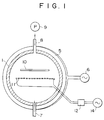
- Electrodes 2, 3 are disposed in parallel with each other in a reaction container 1 for generating glow discharge plasma. Electric power with a commercial frequency of, for example, 60Hz is supplied to these electrodes 2, 3 from a low-frequency power supply 4. A DC or high-frequency power supply can also be used.
- a coil 5 is wound around the reaction container 1, and AC power is supplied from an AC power supply 6.
- a gas mixture of, for example, monosilane and argon is supplied to the reaction container 1 from a cylinder (not shown) via a reaction gas introduction pipe 7. The gas in the reaction container 1 is exhausted through an exhaust pipe 8 by a vacuum pump 9.
- a substrate 10 is located outside the discharge space formed by the electrodes 2, 3 and supported in the direction perpendicular to the faces of the electrodes 2, 3 by a suitable means.
- a thin film can be manufactured in the following manner.
- the vacuum pump 9 is driven to remove gas from the reaction container 1.
- a gas mixture of, for example, monosilane and argon is supplied.
- the pressure inside the reaction container 1 is maintained at 6.65 Pa (0.05 Torr) to 66.5 Pa (0.5 Torr), and electric voltage is applied to the electrodes 2, 3 from the low-frequency power supply 4.
- Glow discharge plasma is generated.
- An AC voltage of, for example, 100Hz is applied to the coil 5 to generate a magnetic field B in the direction perpendicular to the electric field E generated between the electrodes 2 and 3.
- the magnetic flux density in this magnetic field can be about 10 gausses.
- the charged particles are given an initial velocity by this E ⁇ B drift and fly in the direction perpendicular to the electrodes 2, 3 toward the substrate 10.
- the charged particles fly following a Larmor trajectory because of the cyclotron motion due to the magnetic field B generated by the coil 5. Therefore, the charged particles, such as argon ions, rarely hit the substrate 10 directly.
- the silicon (Si) radicals which are electrically neutral, are not influenced by the magnetic field B and divert from the above trajectory of the charged particles to reach the substrate 10 and form a thin amorphous film on the surface thereof. Because the Si radicals collide with the charged particles flying along the Larmor trajectory, the thin amorphous film is formed not only in front of the electrodes 2, 3, but also in areas to the left and the right thereof. Furthermore, because the magnetic field B is varied by the AC power supply 6, the thin amorphous film can be formed on the surface of the substrate 10 uniformly. Also, because the electrodes 2, 3 can be long as long as they fit inside the reaction container 1, even if the substrate 10 is long, the thin amorphous film can be formed uniformly on its surface.
- a film can easily be formed on a large area by generating a magnetic field B in the direction perpendicular to the discharge electric field E between the electrodes generating glow discharge plasma.
- this apparatus has the following problems.
- a plasma CVD apparatus which comprises a reaction container, a means for introducing a reaction gas into the reaction container and for discharging the reaction gas therefrom, discharge electrodes disposed in the reaction container, a power supply for providing the discharge electrodes with electric power for glow discharge, so that a thin amorphous film can be formed on a surface of a substrate positioned in the reaction container
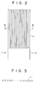
- the plasma CVD apparatus of this invention is characterized in that the discharge electrodes are formed by a planar coil electrode made by bending a single line member in a U shape in an alternating manner, and that the substrate is held substantially in parallel with the discharge electrode.
- a power source which supplies electric power for glow discharge to the discharge electrode preferably has a high frequency of, for example, 13.56MHz
- the distance between the neighboring line elements in the zigzaging planar coil electrode should preferably be 50mm or less. If this distance exceeds 50mm, the distribution of film thickness of amorphous silicon formed on the substrate surface becomes ⁇ 30% or more, and this is not desirable.
- an impedance matching circuit comprising coils and condensers between the power supply and the zigzaging planar coil electrode when supplying the electrode with electric power for generating plasma.
- a coil for generating a magnetic field B in the direction perpendicular to the electric field E generated between the electrode elements, so that the coil surrounds the discharge electrode, as well as a power source supplying the coil with electric current for generating the magnetic field, so that the magnetic field shakes the plasma. It is not necessarily required, however, to shake the plasma by the magnetic field.
- a zigzaging planar coil electrode which is formed by bending a single line member in a U shape in an alternating manner is disposed in the reaction container, so that the electric field around the electrode becomes stronger and the intensity distribution of this field becomes even.
- SiH4 gas SiH light emission intensity (light emission at a wave length of 414nm) becomes uniform. Therefore, the amorphous silicon film formed on the substrate surface has substantially uniform thickness, and the film can be formed at high speeds. Therefore, the plasma CVD apparatus of this invention is suitable for the production of a thin amorphous film which is large in area.
- the zigzaging planar coil electrode is a kind of antenna, its length l should satisfy the following relation with respect to the wavelength ⁇ for the frequency of the power supply: l ⁇ ⁇ /4.
- FIG. 1 is a cross section showing the structure of an embodiment of the plasma CVD apparatus of this invention.
- the same parts as in FIG. 7 are marked by the same reference numerals.
- a zigzaging planar coil electrode 11 is disposed in the reaction container 1 for generating glow discharge plasma.
- This zigzaging planar coil electrode 11 has, as shown in FIGS. 2 and 3, a structure which is obtained by bending a single line member into a U shape in an alternating manner.
- Power with a frequency of, for example, 13.56MHz is supplied to power supply points 11a, 11b on the zigzaging planar coil electrode 11 via an impedance matching circuit 12.
- a coil 5 is disposed around the reaction container 1, and electric power is supplied to the coil from an AC power supply 6.
- this power supply can be a DC source.
- a magnetic field of 50 to 120 gausses is generated by the coil 5.
- a gas mixture of, for example, monosilane and argon is supplied to the reaction container 1 through a reaction gas introduction pipe 7.
- the gas present in the reaction container 1 is exhausted by a vacuum pump 9 through an exhaust pipe 8.
- the substrate 10 is placed in parallel with the zigzaging planar coil electrode 11 and supported by a substrate holder not shown in the drawings.
- a thin film is produced according to the following procedure.
- the gas in the reaction container 1 is exhausted by operating the vacuum pump 9.
- a gas mixture of, for example, monosilane and argon is supplied at rates of 100 to 200cm3/min through the reaction gas introduction pipe 7.
- the pressure inside the reaction container 1 is maintained to 6.65 Pa (0.05 Torr) to 66.5 Pa (0.5 Torr), and electric voltage is applied to the zigzaging planar coil electrode 11 from the high-frequency power supply 14 through the impedance matching circuit 12.
- glow discharge plasma appears around the electrode 11.
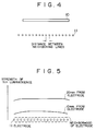
- the light emission is observed through an optical filter which let pass the light having a wavelength of about 414nm only. Results such as shown in FIG. 5 are obtained.
- the emission intensity is more or less constant between the electrode 11 and the substrate 10. From this finding, the distribution of film thickness of a thin amorphous silicon film attaching to the surface of the substrate 10 is inferred to be uniform.
- the distribution of film thickness of the thin amorphous silicon film depends on the flow rate of the reaction gas, pressure, the concentration of SiH4, and electric power as well as on the distance between the neighboring line elements in the zigzaging planar coil electrode 11.
- Substrate material glass Substrate area: 50cm X 50cm
- Kind of reaction gas hydrogen-diluted 20% SiH4 Reaction gas flow rate: 100cm3/min Reaction container pressure: 39.9 Pa (0.3 Torr)
- High-frequency electric power 150W
- the distance between the neighboring line elements in the zigzaging planar coil electrode 11 was set between 5mm and 45mm. Then thin films with an average thickness of 5000 ⁇ were formed. The relation between the distance between the neighboring line elements and the distribution of film thickness is shown in FIG. 6.
- the film thickness distribution was ⁇ 20% or less when the distance between the line elements was 30mm or less.
- an alternating magnetic field a sinusoidal wave of 10 Hz frequency
- the film thickness distribution turned out to be better compared to the cases with no magnetic field.
- the zigzaging planar coil electrode 11 is used as a discharge electrode, and high-frequency power supply of 13.56MHz is used as a power supply for generating plasma, and a magnetic field is applied in the direction perpendicular to the electric field, so that amorphous silicon films with a large area can be produced with such a high speed as 3 to 5 ⁇ /sec.
- this invention by using a zigzaging planar coil electrode as the discharge electrode, the electric field intensity in the neighborhood of the electrode becomes stronger and more uniform, and thus thin films of amorphous silicon having large areas can be produced with high speed. Therefore, this invention is industrially useful and valuable in the manufacture of, for example, amorphous silicon solar cells, thin film semiconductors, optical sensors, and protective layers for semiconductors.
Landscapes
- Chemical & Material Sciences (AREA)
- Engineering & Computer Science (AREA)
- Physics & Mathematics (AREA)
- Plasma & Fusion (AREA)
- Analytical Chemistry (AREA)
- General Chemical & Material Sciences (AREA)
- Chemical Kinetics & Catalysis (AREA)
- Materials Engineering (AREA)
- Mechanical Engineering (AREA)
- Metallurgy (AREA)
- Organic Chemistry (AREA)
- Chemical Vapour Deposition (AREA)
Description
- This invention relates to a plasma CVD (chemical vapor deposition) apparatus suitable for the manufacture of thin films of large areas which are used in various electronic devices, such as amorphous silicon solar cells, thin film semiconductors, optical censors, and protective films for semiconductors.
- With reference to FIG. 7, we shall describe a conventional plasma CVD apparatus which has been used for the manufacture of thin amorphous silicon films with large areas. This technology is known as disclosed, for example, in Japanese patent application No. 106314/1986 (61-106314).
-
Electrodes 2, 3 are disposed in parallel with each other in a reaction container 1 for generating glow discharge plasma. Electric power with a commercial frequency of, for example, 60Hz is supplied to theseelectrodes 2, 3 from a low-frequency power supply 4. A DC or high-frequency power supply can also be used. Acoil 5 is wound around the reaction container 1, and AC power is supplied from an AC power supply 6. A gas mixture of, for example, monosilane and argon is supplied to the reaction container 1 from a cylinder (not shown) via a reaction gas introduction pipe 7. The gas in the reaction container 1 is exhausted through anexhaust pipe 8 by avacuum pump 9. Asubstrate 10 is located outside the discharge space formed by theelectrodes 2, 3 and supported in the direction perpendicular to the faces of theelectrodes 2, 3 by a suitable means. - Using this apparatus, a thin film can be manufactured in the following manner. The
vacuum pump 9 is driven to remove gas from the reaction container 1. Through reaction gas introduction pipe 7, a gas mixture of, for example, monosilane and argon is supplied. The pressure inside the reaction container 1 is maintained at 6.65 Pa (0.05 Torr) to 66.5 Pa (0.5 Torr), and electric voltage is applied to theelectrodes 2, 3 from the low-frequency power supply 4. Glow discharge plasma is generated. An AC voltage of, for example, 100Hz is applied to thecoil 5 to generate a magnetic field B in the direction perpendicular to the electric field E generated between theelectrodes 2 and 3. The magnetic flux density in this magnetic field can be about 10 gausses. - Of the gas supplied from the reaction gas introduction pipe 7, monosilane gas is decomposed by the glow discharge plasma generated between the
electrodes 2 and 3. As a result, silicon (Si) radicals occur and attach to the surface of thesubstrate 10 to form a thin film. - Charged particles, such as argon ions, take the so-called E·B drift motion because of the Coulombic force

 , where V is the velocity of a charged particle. The charged particles are given an initial velocity by this E·B drift and fly in the direction perpendicular to the
electrodes 2, 3 toward thesubstrate 10. However, in the discharge space where the effect of the electric field between theelectrodes 2 and 3 is small, the charged particles fly following a Larmor trajectory because of the cyclotron motion due to the magnetic field B generated by thecoil 5. Therefore, the charged particles, such as argon ions, rarely hit thesubstrate 10 directly. - The silicon (Si) radicals, which are electrically neutral, are not influenced by the magnetic field B and divert from the above trajectory of the charged particles to reach the
substrate 10 and form a thin amorphous film on the surface thereof. Because the Si radicals collide with the charged particles flying along the Larmor trajectory, the thin amorphous film is formed not only in front of theelectrodes 2, 3, but also in areas to the left and the right thereof. Furthermore, because the magnetic field B is varied by the AC power supply 6, the thin amorphous film can be formed on the surface of thesubstrate 10 uniformly. Also, because theelectrodes 2, 3 can be long as long as they fit inside the reaction container 1, even if thesubstrate 10 is long, the thin amorphous film can be formed uniformly on its surface. - According to the conventional apparatus described above, a film can easily be formed on a large area by generating a magnetic field B in the direction perpendicular to the discharge electric field E between the electrodes generating glow discharge plasma. However, this apparatus has the following problems.
- (1) When a film of large area is formed, the electrodes need to be long. In order to generate stable plasma using long electrodes, the frequency of the power supply should be as small as possible. A power supply with a frequency of several 10 to several 100Hz is therefore used. However, under the conditions in which the frequency becomes small and the ion transport during a half period exceeds the distance between the electrodes, secondary electrons discharged from the negative electrode (cathode) due to collisions between the ions play an essential role in maintaining the plasma in the same way as in DC discharge. Therefore, if a film forms on the electrodes and the electrodes become insulated by the film, discharge does not take place in the insulated portion. In this case, the electrode surfaces have to be kept always clean. Therefore, troublesome operations, such as exchanging and cleaning the electrodes very often, are required, and it is a reason for higher costs.
- (2) If a high-frequency plasma source of, for example, 13.56MHz is used in order to alleviate the above disadvantage (1), the secondary electrons discharged from the electrode become inessential in the maintenance of the discharge. Then, even if there exists some insulator, such as a film, on the electrode, glow discharge still forms between the electrodes. However, if the electrodes used are long, because of the skin effect of high frequency, most of the electric current flows in the surface (about 0.01mm) and thus the electric resistance increases. For example, if the length of the electrode is 1m or more, some potential distribution appears on the electrodes and uniform plasma does not result. If we consider this in terms of a distribution constant circuit, it can be shown as in FIG. 8. In FIG. 8, x indicates the distance in the length direction of the electrode. If the resistance R per unit length of the electrode is so large that it cannot be ignored compared with the impedance Z₁, Z₂,..., Zn of the discharge portion, a potential distribution appears in the electrode. Therefore, when a high-frequency power supply is used, it is very difficult and has not been possible in practical applications to form a film having a large area.
- (3) According to the methods (1) and (2) above, when a thin amorphous silicon film of 50cm X 50cm or larger is produced, it has been extremely difficult to keep the distribution of film thickness within ±10% and maintain the speed of film formation at 1Å/sec or more.
- In a plasma CVD apparatus which comprises a reaction container, a means for introducing a reaction gas into the reaction container and for discharging the reaction gas therefrom, discharge electrodes disposed in the reaction container, a power supply for providing the discharge electrodes with electric power for glow discharge, so that a thin amorphous film can be formed on a surface of a substrate positioned in the reaction container, the plasma CVD apparatus of this invention is characterized in that the discharge electrodes are formed by a planar coil electrode made by bending a single line member in a U shape in an alternating manner, and that the substrate is held substantially in parallel with the discharge electrode.
- In this invention, a power source which supplies electric power for glow discharge to the discharge electrode preferably has a high frequency of, for example, 13.56MHz
- In this invention, the distance between the neighboring line elements in the zigzaging planar coil electrode should preferably be 50mm or less. If this distance exceeds 50mm, the distribution of film thickness of amorphous silicon formed on the substrate surface becomes ±30% or more, and this is not desirable.
- In this invention, it is preferred to dispose an impedance matching circuit comprising coils and condensers between the power supply and the zigzaging planar coil electrode when supplying the electrode with electric power for generating plasma.
- In this invention, it is preferred to dispose a coil for generating a magnetic field B in the direction perpendicular to the electric field E generated between the electrode elements, so that the coil surrounds the discharge electrode, as well as a power source supplying the coil with electric current for generating the magnetic field, so that the magnetic field shakes the plasma. It is not necessarily required, however, to shake the plasma by the magnetic field.
- In this invention, instead of a plurality of the conventional parallel planar electrodes, a zigzaging planar coil electrode which is formed by bending a single line member in a U shape in an alternating manner is disposed in the reaction container, so that the electric field around the electrode becomes stronger and the intensity distribution of this field becomes even. For example, when SiH₄ gas is used as a reaction gas, SiH light emission intensity (light emission at a wave length of 414nm) becomes uniform. Therefore, the amorphous silicon film formed on the substrate surface has substantially uniform thickness, and the film can be formed at high speeds. Therefore, the plasma CVD apparatus of this invention is suitable for the production of a thin amorphous film which is large in area. Because the zigzaging planar coil electrode is a kind of antenna, its length l should satisfy the following relation with respect to the wavelength λ for the frequency of the power supply:

-
- FIG. 1 is a cross sectional view showing the structure of the plasma CVD apparatus in the embodiment of this invention;
- FIG. 2 is a plan view of the zigzaging planar coil electrode being used in the above plasma CVD apparatus;
- FIG. 3 is a cross sectional view taken along the III-III line in FIG. 2;
- FIG. 4 is a diagram showing the arrangement of the electrode and the substrate in the above plasma CVD apparatus;
- FIG. 5 is a descriptive drawing showing SiH emission intensity distribution near the electrode in the embodiment of this invention;
- FIG. 6 is a graph showing the relation between the distance between the neighboring line elements in the zigzaging planar coil electrode and the film thickness distribution of amorphous silicon;
- FIG. 7 is a cross sectional view showing the structure of a conventional plasma CVD apparatus; and
- FIG. 8 is for explaining problems associated with the conventional plasma CVD apparatus.
- An embodiment of this invention will be described with reference to the drawings.
- FIG. 1 is a cross section showing the structure of an embodiment of the plasma CVD apparatus of this invention. The same parts as in FIG. 7 are marked by the same reference numerals. A zigzaging
planar coil electrode 11 is disposed in the reaction container 1 for generating glow discharge plasma. This zigzagingplanar coil electrode 11 has, as shown in FIGS. 2 and 3, a structure which is obtained by bending a single line member into a U shape in an alternating manner. Power with a frequency of, for example, 13.56MHz is supplied to power supply points 11a, 11b on the zigzagingplanar coil electrode 11 via animpedance matching circuit 12. Acoil 5 is disposed around the reaction container 1, and electric power is supplied to the coil from an AC power supply 6. Also, this power supply can be a DC source. In this embodiment, a magnetic field of 50 to 120 gausses is generated by thecoil 5. From a cylinder (not shown) a gas mixture of, for example, monosilane and argon is supplied to the reaction container 1 through a reaction gas introduction pipe 7. The gas present in the reaction container 1 is exhausted by avacuum pump 9 through anexhaust pipe 8. Thesubstrate 10 is placed in parallel with the zigzagingplanar coil electrode 11 and supported by a substrate holder not shown in the drawings. - Using this apparatus, a thin film is produced according to the following procedure. The gas in the reaction container 1 is exhausted by operating the
vacuum pump 9. A gas mixture of, for example, monosilane and argon is supplied at rates of 100 to 200cm³/min through the reaction gas introduction pipe 7. The pressure inside the reaction container 1 is maintained to 6.65 Pa (0.05 Torr) to 66.5 Pa (0.5 Torr), and electric voltage is applied to the zigzagingplanar coil electrode 11 from the high-frequency power supply 14 through theimpedance matching circuit 12. Then glow discharge plasma appears around theelectrode 11. The light emission is observed through an optical filter which let pass the light having a wavelength of about 414nm only. Results such as shown in FIG. 5 are obtained. The emission intensity is more or less constant between theelectrode 11 and thesubstrate 10. From this finding, the distribution of film thickness of a thin amorphous silicon film attaching to the surface of thesubstrate 10 is inferred to be uniform. - The distribution of film thickness of the thin amorphous silicon film depends on the flow rate of the reaction gas, pressure, the concentration of SiH₄, and electric power as well as on the distance between the neighboring line elements in the zigzaging
planar coil electrode 11. Experiments for film formation were carried out under the following conditions.
Substrate material: glass
Substrate area: 50cm X 50cm
Kind of reaction gas: hydrogen-diluted 20% SiH₄
Reaction gas flow rate: 100cm³/min
Reaction container pressure: 39.9 Pa (0.3 Torr)
High-frequency electric power: 150W
The distance between the neighboring line elements in the zigzagingplanar coil electrode 11 was set between 5mm and 45mm. Then thin films with an average thickness of 5000Å were formed. The relation between the distance between the neighboring line elements and the distribution of film thickness is shown in FIG. 6. - As shown in FIG. 6, if no magnetic field is applied, the film thickness distribution was ±20% or less when the distance between the line elements was 30mm or less. On the other hand, when an alternating magnetic field (a sinusoidal wave of 10 Hz frequency) of ±80 gausses was applied, the film thickness distribution turned out to be better compared to the cases with no magnetic field.
- According to this embodiment, the zigzaging
planar coil electrode 11 is used as a discharge electrode, and high-frequency power supply of 13.56MHz is used as a power supply for generating plasma, and a magnetic field is applied in the direction perpendicular to the electric field, so that amorphous silicon films with a large area can be produced with such a high speed as 3 to 5Å/sec. - As we have described in the above, according to this invention, by using a zigzaging planar coil electrode as the discharge electrode, the electric field intensity in the neighborhood of the electrode becomes stronger and more uniform, and thus thin films of amorphous silicon having large areas can be produced with high speed. Therefore, this invention is industrially useful and valuable in the manufacture of, for example, amorphous silicon solar cells, thin film semiconductors, optical sensors, and protective layers for semiconductors.
Claims (1)
- A plasma CVD apparatus which comprises a reaction container, a means for introducing a reaction gas into the reaction container and for discharging the reaction gas therefrom, discharge electrodes disposed in the reaction container, and a power supply for providing the discharge electrodes with electric power for glow discharge, so that a thin amorphous film can be formed on a surface of a substrate positioned in the reaction container, characterized in that
the discharge electrodes are formed by a planar coil electrode made by bending a single line member into a U shape in an alternating manner, and that
the substrate is held substantially in parallel with the discharge electrode.
Applications Claiming Priority (2)
| Application Number | Priority Date | Filing Date | Title |
|---|---|---|---|
| JP2123200A JP2785442B2 (en) | 1990-05-15 | 1990-05-15 | Plasma CVD equipment |
| JP123200/90 | 1990-05-15 |
Publications (2)
| Publication Number | Publication Date |
|---|---|
| EP0458085A1 EP0458085A1 (en) | 1991-11-27 |
| EP0458085B1 true EP0458085B1 (en) | 1995-06-21 |
Family
ID=14854674
Family Applications (1)
| Application Number | Title | Priority Date | Filing Date |
|---|---|---|---|
| EP91106776A Expired - Lifetime EP0458085B1 (en) | 1990-05-15 | 1991-04-26 | Plasma CVD apparatus |
Country Status (6)
| Country | Link |
|---|---|
| US (1) | US5405447A (en) |
| EP (1) | EP0458085B1 (en) |
| JP (1) | JP2785442B2 (en) |
| KR (1) | KR950000310B1 (en) |
| CA (1) | CA2041495C (en) |
| DE (1) | DE69110547T2 (en) |
Families Citing this family (12)
| Publication number | Priority date | Publication date | Assignee | Title |
|---|---|---|---|---|
| DE69324849T2 (en) * | 1992-04-16 | 1999-09-23 | Mitsubishi Jukogyo K.K., Tokio/Tokyo | Method and device for plasma-assisted chemical vapor deposition |
| US5591268A (en) * | 1994-10-14 | 1997-01-07 | Fujitsu Limited | Plasma process with radicals |
| US5837090A (en) * | 1994-12-08 | 1998-11-17 | Raytheon Company | Precision aligning and joining of two articles using a flowable adhesive |
| JP3844274B2 (en) | 1998-06-25 | 2006-11-08 | 独立行政法人産業技術総合研究所 | Plasma CVD apparatus and plasma CVD method |
| EP1130948B1 (en) * | 1999-09-09 | 2011-01-26 | Ishikawajima-Harima Heavy Industries Co., Ltd. | Inner-electrode plasma processing apparatus and method of plasma processing |
| JP3872620B2 (en) * | 1999-10-19 | 2007-01-24 | 三菱重工業株式会社 | Plasma generator |
| EP1126504A1 (en) | 2000-02-18 | 2001-08-22 | European Community | Method and apparatus for inductively coupled plasma treatment |
| KR100757717B1 (en) | 2000-04-13 | 2007-09-11 | 도꾸리쯔교세이호진 상교기쥬쯔 소고겡뀨죠 | Thin film forming method, thin film forming apparatus and solar cell |
| US20040020432A1 (en) | 2000-05-17 | 2004-02-05 | Tomoko Takagi | Plasma cvd apparatus and method |
| JP4770029B2 (en) | 2001-01-22 | 2011-09-07 | 株式会社Ihi | Plasma CVD apparatus and solar cell manufacturing method |
| BE1019817A5 (en) * | 2009-10-15 | 2013-01-08 | Europlasma | ELECTRODE WITHOUT MASS. |
| JP5500097B2 (en) * | 2011-02-22 | 2014-05-21 | パナソニック株式会社 | Inductively coupled plasma processing apparatus and method |
Family Cites Families (11)
| Publication number | Priority date | Publication date | Assignee | Title |
|---|---|---|---|---|
| US4526673A (en) * | 1982-09-24 | 1985-07-02 | Spire Corporation | Coating method |
| JPS59145780A (en) * | 1983-02-09 | 1984-08-21 | Ushio Inc | Photochemical vapor deposition device |
| JPH0635661B2 (en) * | 1985-09-03 | 1994-05-11 | 松下電器産業株式会社 | Thin film forming equipment |
| JPH0760798B2 (en) * | 1986-05-09 | 1995-06-28 | 三菱重工業株式会社 | Method and apparatus for forming amorphous thin film |
| EP0244842B1 (en) * | 1986-05-09 | 1994-08-10 | Mitsubishi Jukogyo Kabushiki Kaisha | Apparatus for forming thin film |
| JPS63176461A (en) * | 1987-01-12 | 1988-07-20 | Hitachi Maxell Ltd | Thin film forming device |
| US4960072A (en) * | 1987-08-05 | 1990-10-02 | Ricoh Company, Ltd. | Apparatus for forming a thin film |
| DE3830430A1 (en) * | 1987-09-11 | 1989-03-23 | Japan Synthetic Rubber Co Ltd | METHOD FOR PRODUCING COVERS |
| JPH07118463B2 (en) * | 1988-01-12 | 1995-12-18 | 三菱重工業株式会社 | Plasma CVD equipment |
| US5039376A (en) * | 1989-09-19 | 1991-08-13 | Stefan Zukotynski | Method and apparatus for the plasma etching, substrate cleaning, or deposition of materials by D.C. glow discharge |
| ATE138421T1 (en) * | 1990-03-20 | 1996-06-15 | Diamonex Inc | IMPROVED FILAMENT CVD SYSTEM |
-
1990
- 1990-05-15 JP JP2123200A patent/JP2785442B2/en not_active Expired - Lifetime
-
1991
- 1991-04-26 EP EP91106776A patent/EP0458085B1/en not_active Expired - Lifetime
- 1991-04-26 DE DE69110547T patent/DE69110547T2/en not_active Expired - Fee Related
- 1991-04-30 CA CA002041495A patent/CA2041495C/en not_active Expired - Fee Related
- 1991-05-13 KR KR1019910007645A patent/KR950000310B1/en not_active IP Right Cessation
-
1993
- 1993-06-10 US US08/074,738 patent/US5405447A/en not_active Expired - Fee Related
Also Published As
| Publication number | Publication date |
|---|---|
| US5405447A (en) | 1995-04-11 |
| DE69110547D1 (en) | 1995-07-27 |
| JPH0421781A (en) | 1992-01-24 |
| CA2041495A1 (en) | 1991-11-16 |
| KR910020204A (en) | 1991-12-19 |
| KR950000310B1 (en) | 1995-01-13 |
| DE69110547T2 (en) | 1995-12-14 |
| EP0458085A1 (en) | 1991-11-27 |
| JP2785442B2 (en) | 1998-08-13 |
| CA2041495C (en) | 1998-09-22 |
Similar Documents
| Publication | Publication Date | Title |
|---|---|---|
| EP0784861B1 (en) | Apparatus and method for magnetron in-situ cleaning of plasma reaction chamber | |
| KR100271694B1 (en) | Method and apparatus for reducing perfluorocompound gases from substrate processing equipment emission | |
| US5039376A (en) | Method and apparatus for the plasma etching, substrate cleaning, or deposition of materials by D.C. glow discharge | |
| JP3238082B2 (en) | Electronic device manufacturing equipment | |
| EP0458085B1 (en) | Plasma CVD apparatus | |
| KR101016147B1 (en) | Plasma processing system, antenna, and use of plasma processing system | |
| US20040108469A1 (en) | Beam processing apparatus | |
| EP0280315A2 (en) | Method of forming a diamond film | |
| US20060254519A1 (en) | Locally-efficient inductive plasma coupling for plasma processing system | |
| JP2021502688A (en) | Radiofrequency plasma ion source of linearized energy | |
| JPH09186150A (en) | Apparatus for coating substrate by chemical deposition | |
| JP3069700B1 (en) | Discharge vessel and plasma radical generator provided with the discharge vessel | |
| US6388383B1 (en) | Method of an apparatus for obtaining neutral dissociated gas atoms | |
| JP2989279B2 (en) | Plasma CVD equipment | |
| US6909086B2 (en) | Neutral particle beam processing apparatus | |
| US20040074604A1 (en) | Neutral particle beam processing apparatus | |
| US4500565A (en) | Deposition process | |
| US4915978A (en) | Method and device for forming a layer by plasma-chemical process | |
| JP3086956B2 (en) | Method and apparatus for gas phase synthesis of fine particles by creeping plasma CVD | |
| JPH01283359A (en) | Plasma treatment apparatus | |
| JP3095565B2 (en) | Plasma chemical vapor deposition equipment | |
| EP0418438A1 (en) | Method and apparatus for the plasma etching, substrate cleaning or deposition of materials by D.C. glow discharge | |
| JP3778854B2 (en) | Plasma processing method and plasma processing apparatus | |
| JP2696891B2 (en) | Plasma process equipment | |
| JPH08246146A (en) | Method for plasma treating and device therefor |
Legal Events
| Date | Code | Title | Description |
|---|---|---|---|
| PUAI | Public reference made under article 153(3) epc to a published international application that has entered the european phase |
Free format text: ORIGINAL CODE: 0009012 |
|
| AK | Designated contracting states |
Kind code of ref document: A1 Designated state(s): DE FR GB IT |
|
| 17P | Request for examination filed |
Effective date: 19911129 |
|
| 17Q | First examination report despatched |
Effective date: 19940215 |
|
| GRAA | (expected) grant |
Free format text: ORIGINAL CODE: 0009210 |
|
| AK | Designated contracting states |
Kind code of ref document: B1 Designated state(s): DE FR GB IT |
|
| ITF | It: translation for a ep patent filed | ||
| REF | Corresponds to: |
Ref document number: 69110547 Country of ref document: DE Date of ref document: 19950727 |
|
| ET | Fr: translation filed | ||
| PLBE | No opposition filed within time limit |
Free format text: ORIGINAL CODE: 0009261 |
|
| STAA | Information on the status of an ep patent application or granted ep patent |
Free format text: STATUS: NO OPPOSITION FILED WITHIN TIME LIMIT |
|
| 26N | No opposition filed | ||
| REG | Reference to a national code |
Ref country code: GB Ref legal event code: IF02 |
|
| PGFP | Annual fee paid to national office [announced via postgrant information from national office to epo] |
Ref country code: FR Payment date: 20020410 Year of fee payment: 12 |
|
| PGFP | Annual fee paid to national office [announced via postgrant information from national office to epo] |
Ref country code: GB Payment date: 20020424 Year of fee payment: 12 |
|
| PGFP | Annual fee paid to national office [announced via postgrant information from national office to epo] |
Ref country code: DE Payment date: 20020502 Year of fee payment: 12 |
|
| PG25 | Lapsed in a contracting state [announced via postgrant information from national office to epo] |
Ref country code: GB Free format text: LAPSE BECAUSE OF NON-PAYMENT OF DUE FEES Effective date: 20030426 |
|
| PG25 | Lapsed in a contracting state [announced via postgrant information from national office to epo] |
Ref country code: DE Free format text: LAPSE BECAUSE OF NON-PAYMENT OF DUE FEES Effective date: 20031101 |
|
| GBPC | Gb: european patent ceased through non-payment of renewal fee | ||
| PG25 | Lapsed in a contracting state [announced via postgrant information from national office to epo] |
Ref country code: FR Free format text: LAPSE BECAUSE OF NON-PAYMENT OF DUE FEES Effective date: 20031231 |
|
| REG | Reference to a national code |
Ref country code: FR Ref legal event code: ST |
|
| PG25 | Lapsed in a contracting state [announced via postgrant information from national office to epo] |
Ref country code: IT Free format text: LAPSE BECAUSE OF NON-PAYMENT OF DUE FEES;WARNING: LAPSES OF ITALIAN PATENTS WITH EFFECTIVE DATE BEFORE 2007 MAY HAVE OCCURRED AT ANY TIME BEFORE 2007. THE CORRECT EFFECTIVE DATE MAY BE DIFFERENT FROM THE ONE RECORDED. Effective date: 20050426 |