EP0457432B1 - Lawn mowers - Google Patents
Lawn mowers Download PDFInfo
- Publication number
- EP0457432B1 EP0457432B1 EP91303228A EP91303228A EP0457432B1 EP 0457432 B1 EP0457432 B1 EP 0457432B1 EP 91303228 A EP91303228 A EP 91303228A EP 91303228 A EP91303228 A EP 91303228A EP 0457432 B1 EP0457432 B1 EP 0457432B1
- Authority
- EP
- European Patent Office
- Prior art keywords
- grass
- hood
- handle
- impeller
- mower
- Prior art date
- Legal status (The legal status is an assumption and is not a legal conclusion. Google has not performed a legal analysis and makes no representation as to the accuracy of the status listed.)
- Expired - Lifetime
Links
- 244000025254 Cannabis sativa Species 0.000 claims description 30
- 238000005520 cutting process Methods 0.000 claims description 17
- 241001494496 Leersia Species 0.000 claims description 8
- 230000033001 locomotion Effects 0.000 claims description 3
- 230000026058 directional locomotion Effects 0.000 claims description 2
- 230000012447 hatching Effects 0.000 description 1
Images




Classifications
-
- A—HUMAN NECESSITIES
- A01—AGRICULTURE; FORESTRY; ANIMAL HUSBANDRY; HUNTING; TRAPPING; FISHING
- A01D—HARVESTING; MOWING
- A01D34/00—Mowers; Mowing apparatus of harvesters
- A01D34/01—Mowers; Mowing apparatus of harvesters characterised by features relating to the type of cutting apparatus
- A01D34/412—Mowers; Mowing apparatus of harvesters characterised by features relating to the type of cutting apparatus having rotating cutters
- A01D34/63—Mowers; Mowing apparatus of harvesters characterised by features relating to the type of cutting apparatus having rotating cutters having cutters rotating about a vertical axis
- A01D34/67—Mowers; Mowing apparatus of harvesters characterised by features relating to the type of cutting apparatus having rotating cutters having cutters rotating about a vertical axis hand-guided by a walking operator
- A01D34/68—Mowers; Mowing apparatus of harvesters characterised by features relating to the type of cutting apparatus having rotating cutters having cutters rotating about a vertical axis hand-guided by a walking operator with motor driven cutters or wheels
- A01D34/6806—Driving mechanisms
-
- A—HUMAN NECESSITIES
- A01—AGRICULTURE; FORESTRY; ANIMAL HUSBANDRY; HUNTING; TRAPPING; FISHING
- A01D—HARVESTING; MOWING
- A01D34/00—Mowers; Mowing apparatus of harvesters
- A01D34/01—Mowers; Mowing apparatus of harvesters characterised by features relating to the type of cutting apparatus
- A01D34/412—Mowers; Mowing apparatus of harvesters characterised by features relating to the type of cutting apparatus having rotating cutters
- A01D34/63—Mowers; Mowing apparatus of harvesters characterised by features relating to the type of cutting apparatus having rotating cutters having cutters rotating about a vertical axis
- A01D34/695—Mowers; Mowing apparatus of harvesters characterised by features relating to the type of cutting apparatus having rotating cutters having cutters rotating about a vertical axis supported by an air cushion
-
- A—HUMAN NECESSITIES
- A01—AGRICULTURE; FORESTRY; ANIMAL HUSBANDRY; HUNTING; TRAPPING; FISHING
- A01D—HARVESTING; MOWING
- A01D34/00—Mowers; Mowing apparatus of harvesters
- A01D34/01—Mowers; Mowing apparatus of harvesters characterised by features relating to the type of cutting apparatus
- A01D34/412—Mowers; Mowing apparatus of harvesters characterised by features relating to the type of cutting apparatus having rotating cutters
- A01D34/63—Mowers; Mowing apparatus of harvesters characterised by features relating to the type of cutting apparatus having rotating cutters having cutters rotating about a vertical axis
- A01D34/81—Casings; Housings
-
- A—HUMAN NECESSITIES
- A01—AGRICULTURE; FORESTRY; ANIMAL HUSBANDRY; HUNTING; TRAPPING; FISHING
- A01D—HARVESTING; MOWING
- A01D2101/00—Lawn-mowers
-
- A—HUMAN NECESSITIES
- A01—AGRICULTURE; FORESTRY; ANIMAL HUSBANDRY; HUNTING; TRAPPING; FISHING
- A01D—HARVESTING; MOWING
- A01D43/00—Mowers combined with apparatus performing additional operations while mowing
- A01D43/06—Mowers combined with apparatus performing additional operations while mowing with means for collecting, gathering or loading mown material
- A01D43/077—Mowers combined with apparatus performing additional operations while mowing with means for collecting, gathering or loading mown material with auxiliary means, e.g. fans, for transporting the mown crop
- A01D43/0775—Mowers combined with apparatus performing additional operations while mowing with means for collecting, gathering or loading mown material with auxiliary means, e.g. fans, for transporting the mown crop for airborne lawn-mowers
Definitions
- This invention relates to grass cutting appliances.
- the invention relates to rotary lawn mowers having one or more cutting blades mounted for rotation during operation about a generally vertical axis.
- rotary lawn mowers having one or more cutting blades mounted for rotation during operation about a generally vertical axis.
- a hover-type rotary lawn mower which, when operative is supported by a cushion of air
- a rotary mower which is supported on wheels and which may include a rear roller for producing a striped effect on a mown lawn.
- Mowers falling under category (1) are manually propelled by a user whereas mowers falling under category (2) may be either manually propelled by a user or propelled by a drive-line taken from a power unit connectable via a clutch to one or more wheels or a roller system.
- the power unit combines the functions of driving the rotatable cutting blade(s) and the mower per se.
- Mowers falling within either category may be driven directly or indirectly by either an i/c engine or an electric motor.
- a lawn mower comprises a hood defining a cutting chamber, a cutter member mounted for rotation in a substantially horizontal plane within the cutting chamber, a handle for controlling directional movement of the mower during a cutting operation, a power source disposed remotely from the cutter member and supported from the handle, a drive line for drivingly connecting the power source to the cutter member, a grass collector removably supported on the hood for collecting cut grass, and an inlet aperture disposed adjacent the hood, characterised in that an impeller is mounted within the hood and is drivingly connectable to the power source for producing a stream of pressure air for entraining cut grass and directing the cut grass into the grass collector and in that the stream of pressure air is drawn through the grass collector to the impeller.
- the cutter member and the impeller are co-axially mounted on the common shaft and driven via the drive line.
- the handle is pivotally attachable to the hood.
- the handle could include a tubular member, and the drive line could be housed within the tubular member.
- the grass collector may include an outlet which overlies an inlet to the impeller through which pressure air is drawn. In order to accommodate the handle, the grass collector is preferably slotted to permit pivotal movement of the handle.
- a hood 1 in the form of an inverted dish is pivotally connected to lower end 2A of a handle 2.
- the handle 2 supports an electric motor 3 that is powered by an electric current supplied by a cable 4.
- the electric motor 3 is connected via a drive line 5, within the handle 2, to a drive shaft 6 on which is mounted a rotatable cutting blade 7 and an impeller 8, both contained within a plenum chamber 9 of the hood 1.
- a grass box 10 is supported on the hood 1 as shown and includes a filter grid 11, an inlet 12, air outlet 13, a lid 14 hingedly supported at 15 from the hood 1 and a removable container 16 (shown in outline) for collecting cut grass.
- air is drawn through inlet apertures 17 by the impeller 8 to create a cushion of air to support the mower.
- air is drawn into the grass box 10 by operation of the impeller 8 through inlet 12, grid 11 and air outlet 13.
- the suction created within the grass box 10 draws grass cuttings and other debris into the box through inlet 12 where it is collected in the disposable container 16.
- FIG 1A (where like components are designated with the same reference numbers as figure 1), in addition to drawing debris and grass cutting into the box 10 through inlet 12, debris can be collected while the handle 2 is released by the attachment of a suction hose 18 to an aperture 19 formed on the exterior of the grass box 10 between the air inlet apertures 17 and the grid 11a. When not in use, such an aperture can be sealed with an air-tight cap 20.
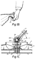
- the grass box 10 can be removed from the hood 1 of the mower by hand by gripping the box along the contour 21, as shown more clearly in figure 1B.
- rotational energy from the drive line 5 is transmitted to the drive shaft 6 to a drive the cutting blade and impeller 8 by means of bevel gears 22a, 22b and 22c.
- Gear 22a is constrained to rotate about the pivotable axis of the handle 2, and gears 22b and 22c are respectively fixed to the drive line 5 and drive shaft 6.
- the drive shaft 6 is held in substantially vertical alignment by means of washers 24.
- the height of the cutting blade 7 relative to the ground datum can be varied by inserting or removing spacing discs 23 along the dirve shaft 6 between the blade 7 and the impellers.
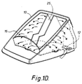
- the grass box 10 has a slot 25 (also shown in fig. 4) in order to accomodate and permit up and down arcurate movement of the handle 2 when the grass box is mounted on the hood 1 of the mower.
- Air and debis is sucked into the grass box 10 through the inlet aperture 12 disposed rearwardly of the hood 1.
- Grass cuttings and debris can either be collected in the box 10 itself or in the removable container 16 supported in spaced relationship within the grass collector box 10 as shown.
- the container 15 is preferably permeable to air, allowing air to flow (as shown) out of it where it can be sucked back into the impeller, and can be of a disposable kind.
- the grass collector box 10 is detached from the hood 1 of the mower in a generally upward direction 26. Collected debris and grass cuttings accumulate within the volume of the box indicated by the hatching.
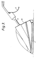
- the appearance of the mower with the grass collector box 10 mounted on the hood 1 is as shown.
- the grass box 10 is opened up from the lid 14 enabling cut grass and collected debris and/or removable container to be removed therefrom.
- the grid 11 is inserted into the grass box 10 by first inserting it into the interior of the lid as shown, and then closing the lid.
- the mower is supported on forward and rearward wheels.
- front wheels may be in the form of conventional casters.
- the wheels are disposed outside the plenum chamber 9 of the hood 1.
- the plenum chamber 9 of this embodiment is in the form of a semi toroid.
- the air circulation or suction system operates in substantially the same manner as previously described with reference to Figure 1.
- the grass collector 10 may carry a disposable bag for receiving grass cuttings.
Landscapes
- Life Sciences & Earth Sciences (AREA)
- Environmental Sciences (AREA)
- Harvester Elements (AREA)
Description
- This invention relates to grass cutting appliances. In particular the invention relates to rotary lawn mowers having one or more cutting blades mounted for rotation during operation about a generally vertical axis. Generally speaking, there are two main categories of rotary lawn mower, namely (1) a hover-type rotary lawn mower which, when operative is supported by a cushion of air, and (2) a rotary mower which is supported on wheels and which may include a rear roller for producing a striped effect on a mown lawn.
- Mowers falling under category (1) are manually propelled by a user whereas mowers falling under category (2) may be either manually propelled by a user or propelled by a drive-line taken from a power unit connectable via a clutch to one or more wheels or a roller system. In the latter case the power unit combines the functions of driving the rotatable cutting blade(s) and the mower per se.
- Mowers falling within either category may be driven directly or indirectly by either an i/c engine or an electric motor.
- It is an object of the present invention to improve the manoeuvrability of type (1) and type (2) mowers as defined above.
- According to the present invention a lawn mower comprises a hood defining a cutting chamber, a cutter member mounted for rotation in a substantially horizontal plane within the cutting chamber, a handle for controlling directional movement of the mower during a cutting operation, a power source disposed remotely from the cutter member and supported from the handle, a drive line for drivingly connecting the power source to the cutter member, a grass collector removably supported on the hood for collecting cut grass, and an inlet aperture disposed adjacent the hood, characterised in that an impeller is mounted within the hood and is drivingly connectable to the power source for producing a stream of pressure air for entraining cut grass and directing the cut grass into the grass collector and in that the stream of pressure air is drawn through the grass collector to the impeller.
- Preferably the cutter member and the impeller are co-axially mounted on the common shaft and driven via the drive line. Conveniently the handle is pivotally attachable to the hood. The handle could include a tubular member, and the drive line could be housed within the tubular member. The grass collector may include an outlet which overlies an inlet to the impeller through which pressure air is drawn. In order to accommodate the handle, the grass collector is preferably slotted to permit pivotal movement of the handle.
- Embodiments of lawn mowers in accordance with the present invention are illustrated in the accompanying drawings, in which :
- Figures 1A, B, C and D are sectional views of a first embodiment of the present invention;
- Figure 2 is an exploded view showing the grass-box separated from the hood;
- Figure 3 is a side view of an assembled mower; and
- Figure 4 is a disassembled view of a mower showing the grid.
- Referring to figure 1, a
hood 1 in the form of an inverted dish is pivotally connected tolower end 2A of a handle 2. The handle 2 supports an electric motor 3 that is powered by an electric current supplied by acable 4. The electric motor 3 is connected via adrive line 5, within the handle 2, to adrive shaft 6 on which is mounted arotatable cutting blade 7 and animpeller 8, both contained within aplenum chamber 9 of thehood 1. Agrass box 10 is supported on thehood 1 as shown and includes afilter grid 11, aninlet 12,air outlet 13, alid 14 hingedly supported at 15 from thehood 1 and a removable container 16 (shown in outline) for collecting cut grass. In use, air is drawn through inlet apertures 17 by theimpeller 8 to create a cushion of air to support the mower. In addition air is drawn into thegrass box 10 by operation of theimpeller 8 throughinlet 12,grid 11 andair outlet 13. The suction created within thegrass box 10 draws grass cuttings and other debris into the box throughinlet 12 where it is collected in thedisposable container 16. - Referring to figure 1A, (where like components are designated with the same reference numbers as figure 1), in addition to drawing debris and grass cutting into the
box 10 throughinlet 12, debris can be collected while the handle 2 is released by the attachment of asuction hose 18 to anaperture 19 formed on the exterior of thegrass box 10 between the air inlet apertures 17 and thegrid 11a. When not in use, such an aperture can be sealed with an air-tight cap 20. - The
grass box 10 can be removed from thehood 1 of the mower by hand by gripping the box along thecontour 21, as shown more clearly in figure 1B. - Referring to figure 1C, rotational energy from the
drive line 5 is transmitted to thedrive shaft 6 to a drive the cutting blade andimpeller 8 by means ofbevel gears gears 22b and 22c are respectively fixed to thedrive line 5 and driveshaft 6. Thedrive shaft 6 is held in substantially vertical alignment by means ofwashers 24. The height of thecutting blade 7 relative to the ground datum can be varied by inserting or removing spacing discs 23 along thedirve shaft 6 between theblade 7 and the impellers. - Refering to figure 1D, the
grass box 10 has a slot 25 (also shown in fig. 4) in order to accomodate and permit up and down arcurate movement of the handle 2 when the grass box is mounted on thehood 1 of the mower. Air and debis is sucked into thegrass box 10 through theinlet aperture 12 disposed rearwardly of thehood 1. Grass cuttings and debris can either be collected in thebox 10 itself or in theremovable container 16 supported in spaced relationship within thegrass collector box 10 as shown. Thecontainer 15 is preferably permeable to air, allowing air to flow (as shown) out of it where it can be sucked back into the impeller, and can be of a disposable kind. - Referring to figure 2, the
grass collector box 10 is detached from thehood 1 of the mower in a generallyupward direction 26. Collected debris and grass cuttings accumulate within the volume of the box indicated by the hatching.
Referring to figure 3, the appearance of the mower with thegrass collector box 10 mounted on thehood 1 is as shown. - Referring to figure 4, the
grass box 10 is opened up from thelid 14 enabling cut grass and collected debris and/or removable container to be removed therefrom. Thegrid 11 is inserted into thegrass box 10 by first inserting it into the interior of the lid as shown, and then closing the lid. - In a further embodiment of the invention the mower is supported on forward and rearward wheels. To assist manoeuvrability front wheels may be in the form of conventional casters. In particular, the wheels are disposed outside the
plenum chamber 9 of thehood 1. In common with our former designs of wheeled or otherwise supported rotary lawn mowers, theplenum chamber 9 of this embodiment is in the form of a semi toroid. The air circulation or suction system operates in substantially the same manner as previously described with reference to Figure 1. In these embodiments, thegrass collector 10, may carry a disposable bag for receiving grass cuttings.
Claims (6)
- A lawn mower comprising a hood defining a cutting chamber, a cutter member mounted for rotation in a substantially horizontal plane within the cutting chamber,
a handle for controlling directional movement of the mower during a cutting operation,
a power source disposed remotely from the cutter member and supported from the handle,
a drive line for drivingly connecting the power source to the cutter member,
a grass collector removably supported on the hood for collecting cut grass, and
an inlet aperture disposed adjacent the hood, characterised in that an impeller is mounted within the hood and is drivingly connectable to the power source for producing a stream of pressure air for entraining cut grass and directing the cut grass into the grass collector and in that the stream of pressure air is drawn through the grass collector to the impeller. - A mower according to claim 1, characterised in that the cutter member and the impeller are coaxially mounted on the common shaft and driven via the drive line.
- A mower according to claim 1 or 2, characterised in that the handle is pivotally attachable to the hood.
- A mower according to any preceding claim, characterised in that the handle includes a tubular member, and the drive line is housed within the tubular member.
- A mower according to any preceding claim, characterised in that the grass collector includes an outlet which overlies an inlet to the impeller through which pressure air is drawn.
- A mower according to any preceding claim, characterised in that the grass collector includes a slot to accommodate a pivotal movement of the handle.
Priority Applications (1)
| Application Number | Priority Date | Filing Date | Title |
|---|---|---|---|
| EP94117827A EP0643905B1 (en) | 1990-04-17 | 1991-04-11 | Lawn mower |
Applications Claiming Priority (2)
| Application Number | Priority Date | Filing Date | Title |
|---|---|---|---|
| GB909008569A GB9008569D0 (en) | 1990-04-17 | 1990-04-17 | Lawn mowers |
| GB9008569 | 1990-04-17 |
Related Child Applications (2)
| Application Number | Title | Priority Date | Filing Date |
|---|---|---|---|
| EP94117827.9 Division-Into | 1991-04-11 | ||
| EP94117827A Division EP0643905B1 (en) | 1990-04-17 | 1991-04-11 | Lawn mower |
Publications (2)
| Publication Number | Publication Date |
|---|---|
| EP0457432A1 EP0457432A1 (en) | 1991-11-21 |
| EP0457432B1 true EP0457432B1 (en) | 1996-02-21 |
Family
ID=10674502
Family Applications (2)
| Application Number | Title | Priority Date | Filing Date |
|---|---|---|---|
| EP94117827A Expired - Lifetime EP0643905B1 (en) | 1990-04-17 | 1991-04-11 | Lawn mower |
| EP91303228A Expired - Lifetime EP0457432B1 (en) | 1990-04-17 | 1991-04-11 | Lawn mowers |
Family Applications Before (1)
| Application Number | Title | Priority Date | Filing Date |
|---|---|---|---|
| EP94117827A Expired - Lifetime EP0643905B1 (en) | 1990-04-17 | 1991-04-11 | Lawn mower |
Country Status (7)
| Country | Link |
|---|---|
| US (1) | US5113642A (en) |
| EP (2) | EP0643905B1 (en) |
| JP (1) | JPH04271718A (en) |
| AU (2) | AU7507691A (en) |
| CA (1) | CA2040690A1 (en) |
| DE (2) | DE69117212T2 (en) |
| GB (1) | GB9008569D0 (en) |
Cited By (1)
| Publication number | Priority date | Publication date | Assignee | Title |
|---|---|---|---|---|
| WO2004107844A1 (en) * | 2003-06-10 | 2004-12-16 | Torque Holdings Limited | A line trimmer lawn mowing attachment |
Families Citing this family (27)
| Publication number | Priority date | Publication date | Assignee | Title |
|---|---|---|---|---|
| US5205113A (en) * | 1990-05-24 | 1993-04-27 | Fassauer Arthur L | Cutting apparatus mulch recycle system |
| GB9103860D0 (en) * | 1991-02-25 | 1991-04-10 | Electrolux Northern | Grass cutting machines |
| GB2254991B (en) * | 1991-04-08 | 1994-11-16 | Atco Qualcast Ltd | Rotary mowers with grass collection |
| GB9114130D0 (en) * | 1991-06-29 | 1991-08-14 | Black & Decker Inc | Lawn mower |
| GB9214930D0 (en) * | 1992-07-14 | 1992-08-26 | Electrolux Northern | Grass cutting machines |
| GB9301932D0 (en) * | 1993-02-01 | 1993-03-17 | Electrolux Northern | Improvements in and relating to collection devices |
| GB9304952D0 (en) * | 1993-03-11 | 1993-04-28 | Electrolux Northern | Improvements in and relating to grass cutting machines |
| GB9311024D0 (en) * | 1993-05-28 | 1993-07-14 | Electrolux Northern | Improvements in grass-mowing machines |
| GB9417169D0 (en) * | 1994-08-25 | 1994-10-12 | Atco Qualcast Ltd | Hovermower decks |
| GB9505345D0 (en) * | 1995-03-16 | 1995-05-03 | Bozeat Miles R W | Improved grass cutting and collection machine |
| GB2333685B (en) | 1998-02-03 | 2000-03-01 | Sabo Maschinenfabrik Gmbh | Lawn mower with collecting device for the cut material |
| DE19850260C2 (en) * | 1998-02-03 | 2002-08-08 | Sabo Maschinenfabrik Gmbh | Lawn mower with collecting device for the clippings |
| US6309469B2 (en) | 1999-03-15 | 2001-10-30 | Shop Vac Corporation | Debris access door |
| US6230361B1 (en) | 1999-12-15 | 2001-05-15 | Shop Vac Corporation | Dust pan closure for a vacuum cleaner |
| GB0117127D0 (en) * | 2001-07-13 | 2001-09-05 | Blanckensee Thomas | Tidy strim |
| JP3776773B2 (en) * | 2001-08-22 | 2006-05-17 | 本田技研工業株式会社 | Electric lawn mower |
| GB2382973B (en) * | 2001-12-14 | 2004-12-08 | Electrolux Outdoor Prod Ltd | Grass cutting machine |
| EP1410708B1 (en) * | 2002-10-17 | 2008-10-08 | Husqvarna UK Limited | Grass collector |
| JP3782790B2 (en) | 2003-04-28 | 2006-06-07 | ダイキン工業株式会社 | Container refrigeration unit |
| EP1731016A3 (en) * | 2005-06-10 | 2007-04-25 | Werner Kress | Lawn mower |
| JP5188156B2 (en) * | 2007-11-19 | 2013-04-24 | 株式会社マキタ | Lawn mower |
| US7849665B2 (en) * | 2009-03-23 | 2010-12-14 | Honda Motor Co., Ltd. | Recirculating grass bagging apparatuses and methods |
| EP2656719B1 (en) * | 2012-04-24 | 2014-11-26 | Robert Bosch Gmbh | Airflow management |
| GB2520001B (en) * | 2013-11-05 | 2019-03-27 | Husqvarna Ab | Hover lawnmower |
| WO2021197390A1 (en) * | 2020-03-31 | 2021-10-07 | Globe (jiangsu) Co., Ltd. | A robotic mower with integrated assemblies |
| US12058957B2 (en) | 2020-05-14 | 2024-08-13 | Globe (jiangsu) Co., Ltd. | Mower |
| CN216567136U (en) | 2021-10-15 | 2022-05-24 | 创科无线普通合伙 | Grass cutter |
Family Cites Families (22)
| Publication number | Priority date | Publication date | Assignee | Title |
|---|---|---|---|---|
| US3110996A (en) * | 1961-03-16 | 1963-11-19 | Flymo Ab | Grass cutting machines |
| US3298163A (en) * | 1961-08-28 | 1967-01-17 | Sunbeam Corp | Rotary electric lawn mower |
| GB1155384A (en) * | 1965-08-25 | 1969-06-18 | Qualcast Ltd | Improvements in or relating to Grass-Cutting Machines |
| GB1240277A (en) * | 1968-10-16 | 1971-07-21 | Qualcast Ltd | Improvements in or relating to grass cutting machines |
| DE6902002U (en) * | 1969-01-20 | 1969-05-29 | Zuendapp Werke Gmbh | LAWN MOWER WITH GRASS COLLECTION DEVICE |
| US3838558A (en) * | 1973-03-05 | 1974-10-01 | D Goodchild | Air cushioned lawn mower and grass collector |
| US3874152A (en) * | 1973-10-12 | 1975-04-01 | Outboard Marine Corp | Grass catcher unit for rotary lawnmowers |
| CA1039514A (en) * | 1975-08-21 | 1978-10-03 | Edward Szymanis | Rotary lawn mower with separate grass pick up |
| US4043100A (en) * | 1975-10-24 | 1977-08-23 | Aumann Richard F | Cutting machine |
| SE7901767L (en) * | 1978-03-13 | 1979-09-14 | Flymo Sa | LAWNMOWER |
| GB1575388A (en) * | 1978-05-23 | 1980-09-24 | Flymo Sa | Hover-type lawn mower |
| CA1093312A (en) * | 1978-07-07 | 1981-01-13 | Edward Szymanis | Safety lawn mower and grass collector |
| DE2930042A1 (en) * | 1979-07-24 | 1981-02-12 | Zuendapp Werke Gmbh | Hand guided lawn mower - has grass box completely enclosing motor and forming guide channel |
| EP0037871B1 (en) * | 1980-04-15 | 1983-11-09 | Flymo Limited | Collecting accessory for air supported lawn mower |
| GB2127665B (en) * | 1982-10-08 | 1986-03-12 | John Edwin Hindmarch | Mower |
| JPS61146110A (en) * | 1984-12-20 | 1986-07-03 | 株式会社共立 | Lawn mower |
| GB2199226B (en) * | 1986-12-29 | 1990-10-10 | Kubota Ltd | Cutter-trimmer of the walk-behind type |
| DE3741019A1 (en) * | 1987-12-03 | 1989-06-15 | Wolf Geraete Gmbh | GRASS CATCHER FOR LAWN MOWERS |
| JPH01225413A (en) * | 1988-03-04 | 1989-09-08 | Kubota Ltd | Loan mower |
| US4974403A (en) * | 1988-03-04 | 1990-12-04 | Kubota, Ltd. | Grass cutting system having a grass catcher |
| GB9008571D0 (en) * | 1990-04-17 | 1990-06-13 | Electrolux Northern | Lawn mowers |
| US5048275A (en) * | 1990-09-07 | 1991-09-17 | Fassauer Arthur L | Air-floated apparatus having structural channel member and pressure seal |
-
1990
- 1990-04-17 GB GB909008569A patent/GB9008569D0/en active Pending
-
1991
- 1991-04-11 EP EP94117827A patent/EP0643905B1/en not_active Expired - Lifetime
- 1991-04-11 DE DE69117212T patent/DE69117212T2/en not_active Expired - Fee Related
- 1991-04-11 EP EP91303228A patent/EP0457432B1/en not_active Expired - Lifetime
- 1991-04-11 DE DE69132452T patent/DE69132452D1/en not_active Expired - Lifetime
- 1991-04-17 CA CA002040690A patent/CA2040690A1/en not_active Abandoned
- 1991-04-17 AU AU75076/91A patent/AU7507691A/en not_active Abandoned
- 1991-04-17 US US07/686,584 patent/US5113642A/en not_active Expired - Fee Related
- 1991-04-17 JP JP3179427A patent/JPH04271718A/en active Pending
-
1994
- 1994-06-20 AU AU64847/94A patent/AU6484794A/en not_active Abandoned
Cited By (1)
| Publication number | Priority date | Publication date | Assignee | Title |
|---|---|---|---|---|
| WO2004107844A1 (en) * | 2003-06-10 | 2004-12-16 | Torque Holdings Limited | A line trimmer lawn mowing attachment |
Also Published As
| Publication number | Publication date |
|---|---|
| EP0643905A2 (en) | 1995-03-22 |
| EP0643905B1 (en) | 2000-10-18 |
| EP0457432A1 (en) | 1991-11-21 |
| US5113642A (en) | 1992-05-19 |
| GB9008569D0 (en) | 1990-06-13 |
| CA2040690A1 (en) | 1991-10-18 |
| DE69132452D1 (en) | 2000-11-23 |
| EP0643905A3 (en) | 1995-04-26 |
| DE69117212T2 (en) | 1996-07-04 |
| JPH04271718A (en) | 1992-09-28 |
| AU7507691A (en) | 1991-10-24 |
| DE69117212D1 (en) | 1996-03-28 |
| AU6484794A (en) | 1994-08-25 |
Similar Documents
| Publication | Publication Date | Title |
|---|---|---|
| EP0643905B1 (en) | Lawn mower | |
| US4597203A (en) | Convertible snowblower using rectangular shroud interface | |
| US5231827A (en) | Lawn and garden chipper shredder vacuum apparatus | |
| EP0457433B1 (en) | Lawn mowers | |
| US5894630A (en) | Air conducting convertor for string trimmer | |
| US7185478B1 (en) | Automated lawn cutting and vacuum system | |
| US20080127621A1 (en) | Combined weed whacker, blower and vacuum apparatus | |
| US3588179A (en) | Power mower clipping-collecting attachment-collecting trailer therefor | |
| US20070209346A1 (en) | Combined weed whacker, blower and vacuum apparatus | |
| CN109258076B (en) | Multifunctional mower | |
| US3672139A (en) | Trimmer-edger debris catcher | |
| CN219165165U (en) | Mowing device | |
| GB2311462A (en) | Blower vacuum | |
| CN212753314U (en) | Weeding device for greening | |
| JPH06169624A (en) | Variable collector in lawn mower | |
| CN217470760U (en) | A garden greening garden weeding device | |
| CN216314019U (en) | Novel hand-push type lawn mower | |
| CN218184071U (en) | Weeder with collect weeds function | |
| CN221355025U (en) | Mower with splash-proof structure | |
| CN214757935U (en) | Grass cutting device is used in landscape garden | |
| CN221264457U (en) | Green maintenance device that plants in gardens | |
| EP0821867B1 (en) | Lawnmower with grass collector | |
| CN212034878U (en) | Weeding device for landscaping | |
| CN221996062U (en) | Agricultural mower convenient to adjust | |
| CN218244502U (en) | Small-size weeder of hand-held type |
Legal Events
| Date | Code | Title | Description |
|---|---|---|---|
| PUAI | Public reference made under article 153(3) epc to a published international application that has entered the european phase |
Free format text: ORIGINAL CODE: 0009012 |
|
| AK | Designated contracting states |
Kind code of ref document: A1 Designated state(s): BE DE DK ES FR GB IT NL SE |
|
| 17P | Request for examination filed |
Effective date: 19920113 |
|
| 17Q | First examination report despatched |
Effective date: 19921201 |
|
| RAP1 | Party data changed (applicant data changed or rights of an application transferred) |
Owner name: ELECTROLUX OUTDOOR PRODUCTS LIMITED |
|
| GRAA | (expected) grant |
Free format text: ORIGINAL CODE: 0009210 |
|
| AK | Designated contracting states |
Kind code of ref document: B1 Designated state(s): BE DE DK ES FR GB IT NL SE |
|
| PG25 | Lapsed in a contracting state [announced via postgrant information from national office to epo] |
Ref country code: IT Free format text: LAPSE BECAUSE OF FAILURE TO SUBMIT A TRANSLATION OF THE DESCRIPTION OR TO PAY THE FEE WITHIN THE PRESCRIBED TIME-LIMIT;WARNING: LAPSES OF ITALIAN PATENTS WITH EFFECTIVE DATE BEFORE 2007 MAY HAVE OCCURRED AT ANY TIME BEFORE 2007. THE CORRECT EFFECTIVE DATE MAY BE DIFFERENT FROM THE ONE RECORDED. Effective date: 19960221 Ref country code: NL Free format text: LAPSE BECAUSE OF FAILURE TO SUBMIT A TRANSLATION OF THE DESCRIPTION OR TO PAY THE FEE WITHIN THE PRESCRIBED TIME-LIMIT Effective date: 19960221 Ref country code: DK Effective date: 19960221 Ref country code: ES Free format text: THE PATENT HAS BEEN ANNULLED BY A DECISION OF A NATIONAL AUTHORITY Effective date: 19960221 |
|
| XX | Miscellaneous (additional remarks) |
Free format text: TEILANMELDUNG 94117827.9 EINGEREICHT AM 11/04/91. |
|
| PGFP | Annual fee paid to national office [announced via postgrant information from national office to epo] |
Ref country code: FR Payment date: 19960229 Year of fee payment: 6 |
|
| REF | Corresponds to: |
Ref document number: 69117212 Country of ref document: DE Date of ref document: 19960328 |
|
| PGFP | Annual fee paid to national office [announced via postgrant information from national office to epo] |
Ref country code: BE Payment date: 19960401 Year of fee payment: 6 |
|
| ET | Fr: translation filed | ||
| PG25 | Lapsed in a contracting state [announced via postgrant information from national office to epo] |
Ref country code: SE Effective date: 19960521 |
|
| NLV1 | Nl: lapsed or annulled due to failure to fulfill the requirements of art. 29p and 29m of the patents act | ||
| PLBE | No opposition filed within time limit |
Free format text: ORIGINAL CODE: 0009261 |
|
| STAA | Information on the status of an ep patent application or granted ep patent |
Free format text: STATUS: NO OPPOSITION FILED WITHIN TIME LIMIT |
|
| 26N | No opposition filed | ||
| PG25 | Lapsed in a contracting state [announced via postgrant information from national office to epo] |
Ref country code: BE Effective date: 19970430 |
|
| PGFP | Annual fee paid to national office [announced via postgrant information from national office to epo] |
Ref country code: DE Payment date: 19970430 Year of fee payment: 7 |
|
| BERE | Be: lapsed |
Owner name: ELECTROLUX OUTDOOR PRODUCTS LTD Effective date: 19970430 |
|
| PG25 | Lapsed in a contracting state [announced via postgrant information from national office to epo] |
Ref country code: FR Free format text: LAPSE BECAUSE OF NON-PAYMENT OF DUE FEES Effective date: 19971231 |
|
| REG | Reference to a national code |
Ref country code: FR Ref legal event code: ST |
|
| PG25 | Lapsed in a contracting state [announced via postgrant information from national office to epo] |
Ref country code: DE Free format text: LAPSE BECAUSE OF NON-PAYMENT OF DUE FEES Effective date: 19990202 |
|
| REG | Reference to a national code |
Ref country code: GB Ref legal event code: IF02 |
|
| PGFP | Annual fee paid to national office [announced via postgrant information from national office to epo] |
Ref country code: GB Payment date: 20060307 Year of fee payment: 16 |
|
| GBPC | Gb: european patent ceased through non-payment of renewal fee |
Effective date: 20070411 |
|
| PG25 | Lapsed in a contracting state [announced via postgrant information from national office to epo] |
Ref country code: GB Free format text: LAPSE BECAUSE OF NON-PAYMENT OF DUE FEES Effective date: 20070411 |