EP0457323A2 - Device for digital measuring the string yarn length from a warp beam of a warp knitting machine - Google Patents
Device for digital measuring the string yarn length from a warp beam of a warp knitting machine Download PDFInfo
- Publication number
- EP0457323A2 EP0457323A2 EP91107951A EP91107951A EP0457323A2 EP 0457323 A2 EP0457323 A2 EP 0457323A2 EP 91107951 A EP91107951 A EP 91107951A EP 91107951 A EP91107951 A EP 91107951A EP 0457323 A2 EP0457323 A2 EP 0457323A2
- Authority
- EP
- European Patent Office
- Prior art keywords
- warp beam
- pressure roller
- warp
- roller
- lever
- Prior art date
- Legal status (The legal status is an assumption and is not a legal conclusion. Google has not performed a legal analysis and makes no representation as to the accuracy of the status listed.)
- Granted
Links
Images

Classifications
-
- D—TEXTILES; PAPER
- D04—BRAIDING; LACE-MAKING; KNITTING; TRIMMINGS; NON-WOVEN FABRICS
- D04B—KNITTING
- D04B27/00—Details of, or auxiliary devices incorporated in, warp knitting machines, restricted to machines of this kind
- D04B27/10—Devices for supplying, feeding, or guiding threads to needles
- D04B27/16—Warp beams; Bearings therefor
- D04B27/20—Warp beam driving devices
- D04B27/22—Warp beam driving devices electrically controlled
-
- G—PHYSICS
- G01—MEASURING; TESTING
- G01B—MEASURING LENGTH, THICKNESS OR SIMILAR LINEAR DIMENSIONS; MEASURING ANGLES; MEASURING AREAS; MEASURING IRREGULARITIES OF SURFACES OR CONTOURS
- G01B7/00—Measuring arrangements characterised by the use of electric or magnetic techniques
- G01B7/02—Measuring arrangements characterised by the use of electric or magnetic techniques for measuring length, width or thickness
- G01B7/04—Measuring arrangements characterised by the use of electric or magnetic techniques for measuring length, width or thickness specially adapted for measuring length or width of objects while moving
- G01B7/042—Measuring arrangements characterised by the use of electric or magnetic techniques for measuring length, width or thickness specially adapted for measuring length or width of objects while moving for measuring length
Definitions
- the invention relates to a device according to the preamble of claim 1.
- Such a device is known from DE-OS 23 07 152.
- the pressure roller resting on the warp beam drives a tachogenerator directly, which thus generates a signal corresponding to the drawn threads.
- the tachometer generator can also be a digital measuring value transmitter, that is to say a pulse generator, the pulses of which, with regard to their spacing, are a measure of the thread length emitted.
- relatively soft rubber is usually used as the material for the pressure roller.
- the invention has for its object to design the drive of the driven by the pressure roller pulse generator so that a very precise drive of the pulse generator is guaranteed over practically any long operating times and the thread length pulses emitted by the pulse generator enable precise control of the rotation of the warp beam.
- the drive roller which is not in contact with the warp beam because of the use of the pressure roller as an intermediate roller, can easily be made from a material with a hard surface, with a high accuracy with regard to the diameter of the drive roller being able to be maintained, so that practically any length of time Operating periods result in wear-free working of the drive roller with a constant diameter and thus constant accuracy of the thread length control. It does not matter whether the pressure roller is subject to wear, since as an intermediate roller, even if the diameter becomes smaller due to wear and tear in the event of slippage-free entrainment, the exact length of the thread taken from the warp beam is transferred to the drive roller, so that there is trouble-free operation over large operating periods and results in smooth operation of the device with high accuracy.
- the device is expediently designed so that the The pressure roller is mounted on a lever articulated on a swivel arm and biased towards the warp beam in such a way that the pressure roller rotates the lever away from the warp beam in its pressed state and the lever on the warp beam in its lifted state, one attached to the swivel arm Limit switch - actuated by the lever - assumes its one switch position (e.g. closed) in the pressed state and its other switch position (e.g. open) in the raised state, into which the limit switch when the swivel arm swings away from the warp beam during the rotational movement of the Lever with the pressure roller still resting on the warp beam.
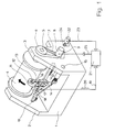
- FIG. 1 shows a basic illustration of a known warp knitting machine with the machine frame 1, the side walls 2 and 3 of which support the warp beam 4.
- the Kettbaum drive motor 8 is fastened to the side wall 3 via the console 9.
- the bar 10 extends between the side walls 2 and 3 and is supported by the side walls 2 and 3 in a known manner, not shown in detail here. Warp knitting machines are usually equipped with several laying bars, but this need not be discussed in this context.
- the laying bar 10 can carry out in a known manner an offset movement running in its longitudinal direction, which is designated here by the distance "D".
- the pressure roller 11 bears against the winding of the warp beam 4 and, due to its friction with respect to the warp beam 4, is carried along by the latter without slippage, so that the path length of the surface of the warp beam 4 covered during the rotation of the warp beam 4 extends completely onto the pressure roller 11 transmits and takes them accordingly.
- the pressure roller 11 is rotatably mounted on the axis 12 which is supported by the lever 13.
- the lever 13 is articulated on the swivel arm 14, which in turn is mounted on the side wall 3 via the axis 15. The interaction of lever 13 and swivel arm 14 is discussed in more detail below in connection with FIGS. 2 to 4.
- the drive roller 16 is mounted on the lever 13 and is carried along without slippage by the pressure roller 11 acting as an intermediate roller.
- the pressure roller 11 which in turn transmits its movement to the drive roller 16 without slippage, so that any distance traveled by the surface of the warp beam 4 is fully transferred to the drive roller 16, the surface of which thus runs through the same length as the surface of the warp beam.
- the drive roller 16 is connected via the axis 17 to the pulse generator 18 which is attached to the lever 13 and which, depending on the progression of the surface of the warp beam 4 and thus the thread take-off, emits a corresponding number of pulses via the line 19.
- the number of these thread length pulses 20 is a measure of the thread length drawn off the warp beam 4.
- the thread length pulses 20 are fed via line 19 into the control circuit 21, which also receives a pulse train in a known manner from the pulse generator 22 via line 23.
- the pulse generator 22 is driven by the main shaft 24 of the warp knitting machine.
- the drive motor of the Warp knitting machine is not shown here.
- the control circuit 21 On the basis of the pulse trains supplied to the control circuit 21, the control circuit 21 generates in a known manner a control signal which is output via the line 25 and which controls the drive motor 8 for the warp beam 4.
- the required thread feed is adjusted in a known manner depending on the thread requirement on the knitting tools, in particular the offset movement of the laying bar 10, by corresponding regulation of the speed of the warp beam 4.
- the drive roller 16, which takes up exactly the distance traveled by the warp beam 4 via the pressure roller 11, is either made of hard material or with a hardened surface, so that it is carried over long periods of operation by the pressure roller 11 without wear and tear, in particular without wear of the pressure roller 11 can result in falsification of the delivery of the thread length pulses 20 with respect to the twisting of the warp beam 4. Even if the diameter of the pressure roller 11 is reduced due to wear, the drive roller 16 with its rotation always reproduces exactly the distance covered by the surface of the warp beam 4. It is only necessary to ensure in a known manner that even when the pressure roller 11 is worn and the diameter of the pressure roller 11 is correspondingly reduced, the drive roller 16 always bears against the pressure roller 11 and is taken along by it without slippage.
- the drive roller 16 the design of which is therefore independent of the conditions of entrainment through the surface of the warp beam 4, can not only be made of any hard material, it is also possible to give it any desired diameter.
- This diameter of the drive roller 16 is defined here so that the thread length pulses 20, which appear evenly along the circumference of the drive roller 16 with one revolution of the drive roller 16, each correspond to a fraction of a minimal displacement movement of the bar 10. If e.g. B.
- the circumference of the drive roller 16 is appropriately chosen by appropriate dimensioning of its diameter so that there is a distance between these given a number of thread length pulses 20 per revolution of the drive roller 16 given by the pulse generator 18 Pulse results, which corresponds to about 0.1 mm of thread length drawn off the warp beam 4.
- Pulse results which corresponds to about 0.1 mm of thread length drawn off the warp beam 4.
- the accuracy of the control of the rotation of the warp beam 4 can be increased accordingly, which is important if, in the case of the offset movement of the laying bar 10 and the processing of the threads per stitch row caused by the knitting tools, particularly short thread lengths result, which then occur during a revolution of the main shaft 24 for this processing adapted thread feed can be fed with great accuracy by controlling the rotation of the warp beam 4.
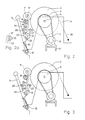
- FIG. 2 shows a detail from FIG. 1 in a side view, in which, in addition to the warp beam 4 and its drive, the pivot arm 14 with the components arranged thereon is also shown.
- Figure 2 shows the device in the operating position, in which the pressure roller 11 rests on the surface of the warp beam 4 and is carried by it.
- the pressure roller 11 transmits the rotary movement to the drive roller 16.
- the pressure roller 11 and the drive roller 16 are mounted on the lever 13, which is pivotably articulated on the swivel arm 14 by means of the axis 26.
- the lever 13 can be rotated back and forth between the adjustable stops 27 and 28, being pressed by the spring 29 in the direction of the warp beam 4.
- the pivot arm 14 pivotably mounted on the axis 15 is biased by the spring 30 in the direction of the warp beam 4 in such a way that the force of the spring 30 overcomes that of the spring 29.
- the lever 13 rests on the stop 28, as a result of which the possible pivoting movement of the swivel arm 14 toward the warp beam 4 is limited.
- the limit switch 31 is attached to the swivel arm 14, the plunger 32 (see enlarged illustration in FIG. 2a) being pushed in by the lever 13 and thereby closing the contact 33 of the limit switch 31.
- the closing of the contact 33 can be used, for example, for the warp knitting machine in question to put into operation and to keep. If for some reason, in particular also when inadvertently actuated, the swivel arm 14 is pivoted away from the warp beam 4, the swivel arm 14 assumes the switch-off position shown in FIG. 3, in which the lever 13 is rotated away from the swivel arm 14 under the action of the spring 29, the pressure roller 11 initially remains in contact with the warp beam 4.
- the locking pin 34 is provided, with which the swivel arm 14 is held in the known manner in the inoperative position shown in Figure 4.
Landscapes
- Engineering & Computer Science (AREA)
- Textile Engineering (AREA)
- Physics & Mathematics (AREA)
- General Physics & Mathematics (AREA)
- Knitting Machines (AREA)
- Treatment Of Fiber Materials (AREA)
- Length Measuring Devices With Unspecified Measuring Means (AREA)
Abstract
Description
Die Erfindung bezieht sich auf eine Vorrichtung gemäß dem Oberbegriff des Anspruchs 1.The invention relates to a device according to the preamble of claim 1.
Eine derartige Vorrichtung ist aus der DE-OS 23 07 152 bekannt. Bei der bekannten Vorrichtung treibt die am Kettbaum anliegende Andrückrolle direkt einen Tachogenerator, der damit ein den abgezogenen Fäden entsprechendes Signal erzeugt. Bei dem Tachogenerator kann es sich auch um einen digitalen Meßwertgeber, also um einen Impulsgenerator handeln, dessen Impulse hinsichtlich ihres Abstandes ein Maß für die jeweils abgegebene Fadenlänge ist. Um dabei infolge Anliegens der Andrückrolle Beschädigungen der auf dem Kettbaum aufgewickelten Fäden zu vermeiden, wird üblicherweise als Material für die Andrückrolle relativ weiches Gummi verwendet.Such a device is known from DE-OS 23 07 152. In the known device, the pressure roller resting on the warp beam drives a tachogenerator directly, which thus generates a signal corresponding to the drawn threads. The tachometer generator can also be a digital measuring value transmitter, that is to say a pulse generator, the pulses of which, with regard to their spacing, are a measure of the thread length emitted. In order to avoid damage to the threads wound on the warp beam as a result of the pressure roller being in contact, relatively soft rubber is usually used as the material for the pressure roller.
Es ist weiterhin aus der DE-OS 23 51 431 bekannt, die Impulse (Fadenlängen-Impulse), die von dem von der Andrückrolle angetriebenen Impulsgenerator abgegeben werden, mit einem vorgegebenen Impulszug zu vergleichen, um aus dem Vergleich ein Maß für die Steuerung der Drehung des Kettbaumes abzuleiten. Auch bei der betreffenden bekannten Vorrichtung dient die Andrückrolle zum direkten Antrieb des Impulsgenerators.It is also known from DE-OS 23 51 431 to compare the pulses (thread length pulses), which are emitted by the pulse generator driven by the pressure roller, with a predetermined pulse train, in order to measure the control of the rotation from the comparison deriving the warp beam. In the known device in question, the pressure roller is used to directly drive the pulse generator.
Der Erfindung liegt die Aufgabe zugrunde, den Antrieb des über die Andrückrolle angetriebenen Impulsgenerators so zu gestalten, daß über praktisch beliebig lange Betriebszeiten ein sehr genauer Antrieb des Impulsgenerators gewährleistet ist und die vom Impulsgenerator abgegebenen Fadenlängen-Impulse eine genaue Steuerung der Drehung des Kettbaumes ermöglichen.The invention has for its object to design the drive of the driven by the pressure roller pulse generator so that a very precise drive of the pulse generator is guaranteed over practically any long operating times and the thread length pulses emitted by the pulse generator enable precise control of the rotation of the warp beam.
Erfindungsgemäß geschieht dies durch die im Kennzeichen des Patentanspruchs 1 angegebenen Maßnahmen.According to the invention, this is done by the measures specified in the characterizing part of patent claim 1.
Die Gestaltung des Antriebs des Impulsgenerators unter Ausnutzung der Andrückrolle als Zwischenrolle, die dann schlupffrei die den Impulsgenerator direkt antreibende Antriebsrolle mitnimmt, macht die Drehung der Antriebsrolle und damit des Impulsgenerators in bezug auf den tatsächlichen Fadenabzug frei vom Durchmesser der Andrückrolle und deren eventuellen Ungenauigkeiten, insbesondere also von deren Abnutzung, und läßt in vorteilhafter Weise eine Herstellung der Antriebsrolle zu, bei der diese einerseits mit verschleißfreier Oberfläche und andererseits mit einem vorgegebenen Durchmesser gefertigt werden kann, der darauf Rücksicht nimmt, daß die von der Antriebsrolle mittels des Impulsgenerators erzeugten Fadenlängen-Impulse, die je eine bestimmte Fadenlänge repräsentieren, so dicht aufeinander folgen, daß sich damit für die weitere Verarbeitung der Fadenlängen-Impulse eine Aufteilung in Längenabschnitte der abgezogenen Fäden ergibt, die mit hoher und ausreichender Genauigkeit auf den jeweils durch die betreffenden Legung bzw. Musterung erforderlichen Fadenverbrauch Rücksicht nimmt. Die Antriebsrolle, die ja wegen der Ausnutzung der Andrückrolle als Zwischenrolle nicht am Kettbaum anliegt, kann ohne weiteres aus einem eine harte Oberfläche aufweisenden Material gefertigt werden, wobei hinsichtlich des Durchmessers der Antriebsrolle eine hohe Genauigkeit eingehalten werden kann, so daß sich über praktisch beliebig lange Betriebszeiträume ein verschleißfreies Arbeiten der Antriebsrolle mit gieichbleibendem Durchmesser und damit gieichbleibender Genauigkeit der Fadenlängensteuerung ergibt. Es spielt dabei keine Rolle, ob die Andrückrolle dabei einem Verschleiß unterliegt, da diese als Zwischenrolle auch bei infolge Verschleißes kleiner werdendem Durchmesser im Falle schlupffreier Mitnahme jeweils exakt die vom Kettbaum abgezogene Fadenlänge auf die Antriebsrolle überträgt, so daß sich also ein über große Betriebszeiträume störungsfreies und mit hoher Genauigkeit gleichmäßiges Arbeiten der Vorrichtung ergibt.The design of the drive of the pulse generator using the pressure roller as an intermediate roller, which then slippage-free takes the drive roller directly driving the pulse generator, makes the rotation of the drive roller and thus the pulse generator with respect to the actual thread take-off free from the diameter of the pressure roller and its possible inaccuracies, in particular So from their wear and tear, and advantageously allows the drive roller to be manufactured, in which it can be manufactured on the one hand with a wear-free surface and on the other hand with a predetermined diameter, which takes into account that the thread length pulses generated by the drive roller by means of the pulse generator , each of which represents a certain thread length, so closely follow one another that this results in a division into length sections of the drawn threads for the further processing of the thread length impulses, which have a high and sufficient gene attention to the thread consumption required by the respective laying or patterning. The drive roller, which is not in contact with the warp beam because of the use of the pressure roller as an intermediate roller, can easily be made from a material with a hard surface, with a high accuracy with regard to the diameter of the drive roller being able to be maintained, so that practically any length of time Operating periods result in wear-free working of the drive roller with a constant diameter and thus constant accuracy of the thread length control. It does not matter whether the pressure roller is subject to wear, since as an intermediate roller, even if the diameter becomes smaller due to wear and tear in the event of slippage-free entrainment, the exact length of the thread taken from the warp beam is transferred to the drive roller, so that there is trouble-free operation over large operating periods and results in smooth operation of the device with high accuracy.
Um bei dieser Vorrichtung eine Betriebsstörung zu vermeiden, die sich durch ein unerwünschtes Abheben der Andrückrolle vom Kettbaum ergeben würde (bei weiterlaufender Kettenwirkmaschine würde die weitere Fadenzufuhr von dem Kettbaum gestört sein), gestaltet man die Vorrichtung zweckmäßig so, daß die Andrückrolle auf einem an einem Schwenkarm angelenkten, in Richtung auf den Kettbaum vorgespannten, Hebel derart gelagert ist, daß die Andrückrolle in ihrem angedrückten Zustand den Hebel vom Kettbaum weg und in ihrem abgehobenen Zustand den Hebel auf den Kettbaum zu verdreht, wobei ein am Schwenkarm angebrachter Endschalter - vom Hebel betätigt - im angedrückten Zustand seine eine Schaltstellung (z. B. geschlossen) und im abgehobenen Zustand seine andere Schaltstellung (z. B. geöffnet) einnimmt, in die der Endschalter beim Wegschwenken des Schwenkarmes vom Kettbaum weg während der Drehbewegung des Hebels bei noch am Kettbaum anliegender Andrückrolle gelangt.In order to avoid a malfunction in this device, which would result from an undesirable lifting of the pressure roller from the warp beam (if the warp knitting machine continued to feed the thread from the warp beam would be disturbed), the device is expediently designed so that the The pressure roller is mounted on a lever articulated on a swivel arm and biased towards the warp beam in such a way that the pressure roller rotates the lever away from the warp beam in its pressed state and the lever on the warp beam in its lifted state, one attached to the swivel arm Limit switch - actuated by the lever - assumes its one switch position (e.g. closed) in the pressed state and its other switch position (e.g. open) in the raised state, into which the limit switch when the swivel arm swings away from the warp beam during the rotational movement of the Lever with the pressure roller still resting on the warp beam.
Ein ungewolltes oder unerwünschtes Wegschwenken des Schwenkarmes führt damit vor dem Abheben der Andrückrolle vom Wickel des Kettbaumes zu einer Betätigung des Endschalters aufgrund der bei Beginn der Schwenkbewegung ausgelösten Drehbewegung des Hebels, wodurch der Endschalter z. B. geöffnet werden kann, womit sich die Kettenwirkmaschine noch vor dem erwähnten Abheben abschalten läßt. Hierdurch wird eine Fehlsteuerung der Kettenwirkmaschine unmöglich gemacht.An unwanted or undesired pivoting of the swivel arm thus leads before lifting the pressure roller from the winding of the warp beam to an actuation of the limit switch due to the rotary movement of the lever triggered at the start of the swivel movement, whereby the limit switch z. B. can be opened, whereby the warp knitting machine can be switched off before the mentioned lifting. This makes incorrect control of the warp knitting machine impossible.
In den Figuren ist ein Ausführungsbeispiel der Erfindung dargestellt. Es zeigen:
- Figur 1
- eine Kettenwirkmaschine in prinzipieller Darstellung mit Kettbaum und Andrückrolle, wobei aus Gründen der Vereinfachung der Zeichnung die Wirkwerkzeuge weggelassen sind,
Figur 2- in Seitenansicht den Kettbaum mit Andrückrolle in der Betriebslage,
Figur 3- die gleiche Vorrichtung mit noch am Kettbaum anliegender Andrückrolle, jedoch teilweise verschwenktem Schwenkarm (Abschaltlage),
Figur 4- die gleiche Vorrichtung mit vom Kettbaum abgehobener Andrückrolle (Außerbetriebslage).
- Figure 1
- a warp knitting machine in a basic representation with warp beam and pressure roller, the knitting tools being omitted for the sake of simplifying the drawing,
- Figure 2
- in side view the warp beam with pressure roller in the operating position,
- Figure 3
- the same device with the pressure roller still resting on the warp beam, but with the swivel arm partially pivoted (switch-off position),
- Figure 4
- the same device with the pressure roller lifted off the warp beam (out of service position).
Die Figur 1 zeigt in prinzipieller Darstellung eine bekannte Kettenwirkmaschine mit dem Maschinengestell 1, deren Seitenwände 2 und 3 den Kettbaum 4 tragen.FIG. 1 shows a basic illustration of a known warp knitting machine with the machine frame 1, the
Auf der die Seitenwand 3 durchdringenden Achse 5 des Kettbaumes 4 sitzt die Zahnriemenscheibe 6, die über den Zahnriemen 7 vom Kettbaum-Antriebsmotor 8 angetrieben wird. Der Kettbaum-Antriebsmotor 8 ist über die Konsole 9 an der Seitenwand 3 befestigt. Zwischen den Seitenwänden 2 und 3 erstreckt sich die Legebarre 10, die in bekannter, hier nicht im einzelnen dargestellter Weise von den Seitenwänden 2 und 3 getragen wird. Normalerweise sind Kettenwirkmaschinen mit mehreren Legebarren ausgestattet, worauf jedoch in diesem Zusammenhang nicht eingegangen werden braucht. Die Legebarre 10 kann in bekannter Weise eine in ihrer Längsrichtung verlaufende Versatzbewegung ausführen, die hier durch die Distanz "D" bezeichnet ist. Am Wickel des Kettbaumes 4 liegt die Andrückrolle 11 an, die aufgrund ihrer Reibung gegenüber dem Kettbaum 4 von diesem schlupffrei mitgenommen wird, so daß sich die bei der Drehung des Kettbaumes 4 jeweils zurückgelegte Weglänge der Oberfläche des Kettbaumes 4 in vollem Umfang auf die Andrückrolle 11 überträgt und diese entsprechend mitnimmt. Die Andrückrolle 11 ist auf der Achse 12 drehbar gelagert, die von dem Hebel 13 getragen wird. Der Hebel 13 ist an dem Schwenkarm 14 angelenkt, der seinerseits über die Achse 15 an der Seitenwand 3 gelagert ist. Auf das Zusammenwirken von Hebel 13 und Schwenkarm 14 wird weiter unten im Zusammenhang mit den Figuren 2 bis 4 näher eingegangen. Neben der Andrückrolle 11 ist auf dem Hebel 13 die Antriebsrolle 16 gelagert, die schlupffrei von der als Zwischenrolle wirkenden Andrückrolle 11 mitgenommen wird. Bei Drehung des Kettbaumes 4 nimmt dieser also, wie gesagt, die Andrückrolle 11 mit, die ihrerseits schlupffrei ihre Bewegung auf die Antriebsrolle 16 überträgt, so daß jede von der Oberfläche des Kettbaumes 4 zurückgelegte Wegstrecke voll auf die Antriebsrolle 16 übertragen wird, deren Oberfläche damit die gleiche Länge wie die Oberfläche des Kettbaumes durchläuft. Die Antriebsrolle 16 ist über die Achse 17 mit dem an dem Hebel 13 angebrachten Impulsgenerator 18 verbunden, der demgemäß in Abhängigkeit vom Fortschreiten der Oberfläche des Kettbaumes 4 und damit des Fadenabzugs eine entsprechende Anzahl von Impulsen über die Leitung 19 abgibt. Diese Fadenlängen-Impulse 20 stellen hinsichtlich ihrer Anzahl ein Maß für die vom Kettbaum 4 abgezogene Fadenlänge dar.The
Die Fadenlängen-Impulse 20 werden über die Leitung 19 in die Regelschaltung 21 eingespeist, die außerdem in bekannter Weise von dem Impulsgenerator 22 über die Leitung 23 einen Impulszug erhält. Der Impulsgenerator 22 wird über die Hauptwelle 24 der Kettenwirkmaschine angetrieben. Der Antriebsmotor der Kettenwirkmaschine ist hier nicht dargestellt. Aufgrund der der Regelschaltung 21 zugeführten Impulszüge erzeugt die Regelschaltung 21 in bekannter Weise ein über die Leitung 25 abgegebenes Steuersignal, das den Antriebsmotor 8 für den Kettbaum 4 steuert. Durch diese Regelung und Steuerung wird in bekannter Weise je nach Fadenbedarf an den Wirkwerkzeugen, insbesondere der Versatzbewegung der Legebarre 10, die erforderliche Fadenzufuhr durch entsprechende Regelung der Geschwindigkeit des Kettbaumes 4 eingestellt. Die Antriebsrolle 16, die über die Andrückrolle 11 exakt die vom Kettbaum 4 jeweils zurückgelegte Wegstrecke aufnimmt, ist entweder aus hartem Material oder mit gehärteter Oberfläche hergestellt, so daß sie auch über lange Betriebszeiten verschleißfrei von der Andrückrolle 11 mitgenommen wird, ohne daß sich dabei insbesondere durch Abnutzung der Andrückrolle 11 eine Verfälschung der Abgabe der Fadenlängen-Impulse 20 in bezug auf die Verdrehung des Kettbaumes 4 ergeben kann. Auch bei durch Abnutzung sich ergebender Durchmesserverringerung der Andrückrolle 11 gibt die Antriebsrolle 16 mit ihrer Verdrehung stets genau die von der Oberfläche des Kettbaums 4 zurückgelegte Wegstrecke wieder. Dabei muß lediglich in bekannter Weise dafür gesorgt werden, daß auch bei Abnutzung und entsprechender Durchmesserverringerung der Andrückrolle 11 die Antriebsrolle 16 stets an der Andrückrolle 11 anliegt und von dieser schlupffrei mitgenommen wird.The
Die Antriebsrolle 16, deren Gestaltung somit unabhängig von Bedingungen der Mitnahme durch die Oberfläche des Kettbaums 4 ist, kann nicht nur aus beliebig hartem Material hergestellt werden, es ist auch möglich, ihr jeden gewünschten Durchmesser zu geben. Dieser Durchmesser der Antriebsrolle 16 ist hier so festgelegt, daß die Fadenlängen-Impulse 20, die bei einer Umdrehung der Antriebsrolle 16 im Effekt gleichmäßig längs des Umfangs der Antriebsrolle 16 erscheinen, jeweils einem Bruchteil einer minimalen Versatzbewegung der Legebarre 10 entsprechen. Wenn z. B. minimale Legungsbewegungen im Bereich von 1 mm möglich sind, so wird zweckmäßig der Umfang der Antriebsrolle 16 durch entsprechende Dimensionierung ihres Durchmessers so gewählt, daß sich bei durch den Impulsgenerator 18 gegebener Zahl von Fadenlängen-Impulsen 20 pro Umdrehung der Antriebsrolle 16 ein Abstand dieser Impulse ergibt, der etwa 0,1 mm vom Kettbaum 4 abgezogener Fadenlänge entspricht. Selbstverständlich ist es auch möglich, aufgrund eines kürzeren Umfangs der Antriebsrolle 16 bzw. geringeren Durchmessers bei gleicher Zahl von Fadenlängen-Impulsen 20 je Umdrehung der Antriebsrolle 16 die Fadenlängen-Impulse 20 näher aneinanderzurücken, was darauf hinausläuft, daß jeder Fadenlängen-Impuls 20 eine kürzere Länge von vom Kettbaum 4 abgezogenen Fäden repräsentiert. Auf diese Weise kann die Genauigkeit der Steuerung der Drehung des Kettbaumes 4 entsprechend erhöht werden, was dann von Bedeutung ist, wenn bei der Versatzbewegung der Legebarre 10 und der durch die Wirkwerkzeuge bewirkten Verarbeitung der Fäden pro Maschenreihe sich jeweils besonders kurze Fadenlängen ergeben, die dann während einer Umdrehung der Hauptwelle 24 zwecks dieser Verarbeitung angepaßter Fadenzuführung mit großer Genauigkeit durch die Regelung der Drehung des Kettbaumes 4 zugeführt werden können.The
Es sei nunmehr auf die Figuren 2 bis 4 eingegangen, die die in der Figur 1 dargestellte Vorrichtung mit dem Kettbaum 4 und dem Schwenkarm 14 sowie die daran befestigen Bauteile im einzelnen zeigen.2 to 4, which show the device shown in FIG. 1 with the
In der Figur 2 ist ein Ausschnitt aus der Figur 1 in Seitenansicht dargestellt, in der im wesentlichen außer dem Kettbaum 4 mit seinem Antrieb auch der Schwenkarm 14 mit den daran angeordneten Bauteilen dargestellt ist. Figur 2 zeigt die Vorrichtung in der Betriebslage, in der die Andrückrolle 11 an der Oberfläche des Kettbaums 4 anliegt und von diesem mitgenommen wird. Wie bereits anhand der Figur 1 dargelegt, überträgt die Andrückrolle 11 die Drehbewegung auf die Antriebsrolle 16. Andrückrolle 11 und Antriebsrolle 16 sind auf dem Hebel 13 gelagert, der drehbeweglich mittels der Achse 26 an dem Schwenkarm 14 angelenkt ist. Der Hebel 13 kann zwischen den einstellbaren Anschlägen 27 und 28 hin und her gedreht werden, wobei er durch die Feder 29 in Richtung auf den Kettbaum 4 gedrückt wird. Der auf der Achse 15 verschwenkbar gelagerte Schwenkarm 14 wird durch die Feder 30 in Richtung auf den Kettbaum 4 vorgespannt, und zwar derart, daß die Kraft der Feder 30 diejenige der Feder 29 überwindet. In der dargestellten Betriebslage, in der die Andrückrolle 11 am Kettbaum 4 anliegt und von diesem mitgenommen wird, liegt also der Hebel 13 am Anschlag 28 an, wodurch die auf den Kettbaum 4 zu gerichtete mögliche Verschwenkbewegung des Schwenkarms 14 begrenzt ist.FIG. 2 shows a detail from FIG. 1 in a side view, in which, in addition to the
An dem Schwenkarm 14 ist der Endschalter 31 angebracht, dessen Stößel 32 (siehe vergrößerte Darstellung in Figur 2a) durch den Hebel 13 eingeschoben ist und dabei den Kontakt 33 des Endschalters 31 schließt. Das Schließen des Kontaktes 33 kann beispielsweise dazu benutzt werden, die betreffende Kettenwirkmaschine in Betrieb zu setzen und zu halten. Wenn nun aus irgendeinem Grund, insbesondere auch bei ungewollter Betätigung, der Schwenkarm 14 vom Kettbaum 4 weggeschwenkt wird, nimmt der Schwenkarm 14 die in Figur 3 dargestellte Abschaltlage ein, in der unter der Wirkung der Feder 29 der Hebel 13 vom Schwenkarm 14 weggedreht wird, wobei zunächst die Andrückrolle 11 in Berührungskontakt mit dem Kettbaum 4 verbleibt. Diese Verdrehbewegung des Hebels 13 wird schließlich, wie in Figur 3 dargestellt, vom Anschlag 27 begrenzt. Bis zum Erreichen dieser Abschaltstellung, ausgehend von der Betriebsstellung in Figur 2, bleibt die Andrückrolle 11 in Berührungskontakt mit dem Kettbaum 4, so daß also die über die Antriebsrolle 16 bewirkte Erzeugung der Fadenlängen-Impulse 20 zunächst aufrecht erhalten bleibt. Bei der Verdrehbewegung des Hebels 13 vom Anschlag 28 weg wird jedoch der Stößel 32 des Endschalters 31 freigegeben, so daß der Kontakt 33 öffnet (siehe vergrößerte Darstellung in Figur 4a). Damit kann durch diese Öffnung des Kontaktes 33 die Kettenwirkmaschine abgeschaltet werden, während zunächst, wie gesagt, die Andrückrolle 11 noch in Berührungskontakt mit dem Kettbaum 4 verbleibt, so daß sichergestellt ist, daß die von der Audrückrolle 11 und der Antriebsrolle 16 ausgehende Regelung der Fadenzufuhr vor Abschalten der Maschine nicht unterbrochen werden kann.The
Wenn dann der Schwenkarm 14 weiter in die in Figur 4 dargestellte Außerbetriebslage verschwenkt wird, gerät die Andrückrollle 11 außer Berührungskontakt zum Kettbaum 4, womit nunmehr auch der Antrieb der Antriebsrolle 11 unterbleibt und die Abgabe der Fadenlängen-Impulse 20 unterbrochen wird.If the
An der Lagerung der Achse 15 für den Schwenkarm 14 ist der Rastbolzen 34 vorgesehen, mit dem in bekannter Weise der Schwenkarm 14 in der in Figur 4 gezeigten Außerbetriebslage verrastet gehalten wird.On the mounting of the
Es sei noch darauf hingewiesen, daß im Falle der Verwendung mehrerer Kettbäume bzw. Legebarren die in den Figuren 2 bis 4 dargestellte Vorrichtung entsprechend mehrfach vorgesehen werden muß, womit der Abzug von Fäden 35 pro Kettbaum individuell geregelt werden kann.It should also be pointed out that if several warp beams or laying bars are used, the device shown in FIGS. 2 to 4 has to be provided several times, with which the removal of
Claims (2)
Applications Claiming Priority (2)
| Application Number | Priority Date | Filing Date | Title |
|---|---|---|---|
| DE4015784 | 1990-05-16 | ||
| DE4015784A DE4015784A1 (en) | 1990-05-16 | 1990-05-16 | DEVICE FOR DIGITALLY MEASURING THE THREAD LENGTH OF THREADS DRAWN FROM A warp beam of a warp knitting machine |
Publications (3)
| Publication Number | Publication Date |
|---|---|
| EP0457323A2 true EP0457323A2 (en) | 1991-11-21 |
| EP0457323A3 EP0457323A3 (en) | 1992-03-04 |
| EP0457323B1 EP0457323B1 (en) | 1994-08-03 |
Family
ID=6406568
Family Applications (1)
| Application Number | Title | Priority Date | Filing Date |
|---|---|---|---|
| EP91107951A Expired - Lifetime EP0457323B1 (en) | 1990-05-16 | 1991-05-16 | Device for digital measuring the string yarn length from a warp beam of a warp knitting machine |
Country Status (5)
| Country | Link |
|---|---|
| US (1) | US5152158A (en) |
| EP (1) | EP0457323B1 (en) |
| JP (1) | JPH05240636A (en) |
| DE (2) | DE4015784A1 (en) |
| ES (1) | ES2057658T3 (en) |
Cited By (2)
| Publication number | Priority date | Publication date | Assignee | Title |
|---|---|---|---|---|
| US5257462A (en) * | 1991-03-09 | 1993-11-02 | Hacoba Textilmachinen Gmbh & Co. | Apparatus for measuring the length of filamentous textile material |
| CN110921540A (en) * | 2019-12-03 | 2020-03-27 | 北京三一智造科技有限公司 | Winding device and engineering machinery |
Families Citing this family (10)
| Publication number | Priority date | Publication date | Assignee | Title |
|---|---|---|---|---|
| US5524461A (en) * | 1995-04-24 | 1996-06-11 | Techno-Craft, Inc. | Control system for yarn feed gearbox |
| US6640591B1 (en) * | 2002-11-12 | 2003-11-04 | Eugene Haban | Apparatus and method for production of fabrics |
| EP1686207B1 (en) * | 2005-01-31 | 2012-07-04 | Luigi Omodeo Zorini | Textile machine with yarn feeding control |
| US20060210917A1 (en) | 2005-03-18 | 2006-09-21 | Kodak Polychrome Graphics Llc | Positive-working, thermally sensitive imageable element |
| CN101487165B (en) * | 2009-02-25 | 2011-01-05 | 常州市第八纺织机械有限公司 | Warp let-off speed-measuring feedback device of multi-axial warp knitting machine |
| CN102733072A (en) * | 2012-05-31 | 2012-10-17 | 常州市武进五洋纺织机械有限公司 | Warp knitting machine with main shaft encoder device |
| CN102733073A (en) * | 2012-05-31 | 2012-10-17 | 常州市武进五洋纺织机械有限公司 | Encoder device of warp knitting machine |
| US10392734B2 (en) * | 2016-07-03 | 2019-08-27 | Tzu-Chin Hsu | Yarn tension control device |
| DE102017117921B3 (en) | 2017-08-07 | 2019-01-24 | Sick Stegmann Gmbh | Pivoting holding device for a measuring arrangement, in particular a measuring wheel encoder |
| USD986033S1 (en) * | 2021-02-10 | 2023-05-16 | Kevin RENOUF | Winder |
Citations (4)
| Publication number | Priority date | Publication date | Assignee | Title |
|---|---|---|---|---|
| DE2307152A1 (en) * | 1972-02-14 | 1973-08-23 | Platt International Ltd | CHAIN KNITTING MACHINE |
| DE2324698A1 (en) * | 1972-05-22 | 1973-11-29 | North American Rockwell | CONTROL SYSTEM FOR CHAIN RELEASE IN KNITTING MACHINES |
| DE2536082A1 (en) * | 1974-08-14 | 1976-03-04 | K D G Instr Ltd | DEVICE FOR MEASURING THE LENGTH OF LINEAR MATERIAL |
| DE3900296A1 (en) * | 1989-01-07 | 1990-07-12 | Hacoba Textilmaschinen | Method and device for measuring the length of filamentous textile material |
Family Cites Families (9)
| Publication number | Priority date | Publication date | Assignee | Title |
|---|---|---|---|---|
| US2400525A (en) * | 1944-01-03 | 1946-05-21 | Vanity Fair Mills Inc | Knitting machine |
| US2674109A (en) * | 1950-06-14 | 1954-04-06 | Bassist Rudolph | Control method and system for knitting machines |
| US2871685A (en) * | 1955-12-06 | 1959-02-03 | Bassist Rudolph | Control method and electric system for textile machines |
| US3539782A (en) * | 1967-02-16 | 1970-11-10 | Burlington Industries Inc | Apparatus for measuring the length of yarn or the like consumed in a predetermined number of cycles of a cyclically operated machine such as a tricot knitting machine |
| US3727033A (en) * | 1971-02-12 | 1973-04-10 | Travis Mills Corp | Yarn measuring apparatus for use with warp knitting machines |
| FR2203389A5 (en) * | 1972-10-12 | 1974-05-10 | Colman Cocker Cy | Warp knitting yarn feed control - by comparison of signals from impulse gener-ators at main drive and warp beam motors |
| IT999227B (en) * | 1972-11-29 | 1976-02-20 | Incotex Sa | ADJUSTMENT MECHANISM FOR AUTOMATIC WARP UNWINDERS WITH AU TOMATISM SET TO ZERO |
| DD266599A1 (en) * | 1987-12-22 | 1989-04-05 | Textima Veb K | DEVICE FOR FADEN-LENGTH-CONTROLLED CHAIN FEEDING OF A TEXTILE MACHINE, IN PARTICULAR CHAIN EQUIPMENT |
| JP2883340B2 (en) * | 1988-10-17 | 1999-04-19 | 株式会社シマノ | Fishing reel |
-
1990
- 1990-05-16 DE DE4015784A patent/DE4015784A1/en active Granted
-
1991
- 1991-05-14 JP JP3107698A patent/JPH05240636A/en active Pending
- 1991-05-15 US US07/700,482 patent/US5152158A/en not_active Expired - Fee Related
- 1991-05-16 ES ES91107951T patent/ES2057658T3/en not_active Expired - Lifetime
- 1991-05-16 DE DE59102402T patent/DE59102402D1/en not_active Expired - Fee Related
- 1991-05-16 EP EP91107951A patent/EP0457323B1/en not_active Expired - Lifetime
Patent Citations (4)
| Publication number | Priority date | Publication date | Assignee | Title |
|---|---|---|---|---|
| DE2307152A1 (en) * | 1972-02-14 | 1973-08-23 | Platt International Ltd | CHAIN KNITTING MACHINE |
| DE2324698A1 (en) * | 1972-05-22 | 1973-11-29 | North American Rockwell | CONTROL SYSTEM FOR CHAIN RELEASE IN KNITTING MACHINES |
| DE2536082A1 (en) * | 1974-08-14 | 1976-03-04 | K D G Instr Ltd | DEVICE FOR MEASURING THE LENGTH OF LINEAR MATERIAL |
| DE3900296A1 (en) * | 1989-01-07 | 1990-07-12 | Hacoba Textilmaschinen | Method and device for measuring the length of filamentous textile material |
Cited By (3)
| Publication number | Priority date | Publication date | Assignee | Title |
|---|---|---|---|---|
| US5257462A (en) * | 1991-03-09 | 1993-11-02 | Hacoba Textilmachinen Gmbh & Co. | Apparatus for measuring the length of filamentous textile material |
| CN110921540A (en) * | 2019-12-03 | 2020-03-27 | 北京三一智造科技有限公司 | Winding device and engineering machinery |
| CN110921540B (en) * | 2019-12-03 | 2021-06-25 | 北京三一智造科技有限公司 | Winding device and engineering machinery |
Also Published As
| Publication number | Publication date |
|---|---|
| ES2057658T3 (en) | 1994-10-16 |
| EP0457323B1 (en) | 1994-08-03 |
| DE59102402D1 (en) | 1994-09-08 |
| DE4015784C2 (en) | 1992-03-19 |
| EP0457323A3 (en) | 1992-03-04 |
| JPH05240636A (en) | 1993-09-17 |
| US5152158A (en) | 1992-10-06 |
| DE4015784A1 (en) | 1991-11-21 |
Similar Documents
| Publication | Publication Date | Title |
|---|---|---|
| EP0457323B1 (en) | Device for digital measuring the string yarn length from a warp beam of a warp knitting machine | |
| DE3344667A1 (en) | METHOD AND DEVICE FOR ADJUSTING THE MACHINE DENSITY IN KNITTING | |
| DE4439907A1 (en) | Control device in warp knitting machine reduces tension fluctuations | |
| EP0394235B1 (en) | Process for smooth feed of elastic thread and circular knitting machine | |
| DE4032402C2 (en) | ||
| DE2129973B2 (en) | Device for the formation of thread reserves in OHen-End-Splnnmaechinen | |
| DE3923419A1 (en) | MULTI-HEAD EMBROIDERY MACHINE | |
| DE1051698B (en) | Pneumatic arrangement for the automatic lowering of the ring rail on spinning and twisting machines with stationary spindle rail | |
| DE2430544A1 (en) | DEVICE FOR CREATING A THREAD RESERVE AND FOR CHANGING THREAD ON OPEN-END SPINNING MACHINES | |
| DE2221316B1 (en) | Device for the intermediate storage of an excess thread length on an open-end spinning machine | |
| EP0457327B1 (en) | Device for measuring the length of a string yarn from a warp beam of a warp knitting machine | |
| EP0014897B1 (en) | Device for textile machines | |
| EP1106556A2 (en) | Apparatus for pivoting the bobbin cradle of a textil machine | |
| DE2018785A1 (en) | Method for controlling the knotting process on textile machines, in particular automatic winding machines and pneumatic circuit for its implementation | |
| DE2114820A1 (en) | Needle selective actuator - tripping embroidering needle(s) to produce pattern | |
| DE387239C (en) | Footwear sewing machine with hook needle and device for clearing the workpiece when the machine is switched off | |
| DE2437002A1 (en) | Open-end yarn spinning splicing - has a yarn clamp mounted on a pivoted arm to pass broken yarn into spinning chamber | |
| EP0337339B1 (en) | System for controlling a movement | |
| DE3042989A1 (en) | THREAD DELIVERY DEVICE FOR TEXTILE MACHINES | |
| DE1816564A1 (en) | Bobbin case for sewing machines | |
| DE3147163A1 (en) | Process and device for feeding yarn to the stitch forming system of a knitting machine | |
| DE1785410B2 (en) | Device for stopping the drive cylinders of take-up bobbins in a machine for twisting textile thread | |
| DE144317C (en) | ||
| DE53739C (en) | English round knitting loom with goods hanging down on the outside | |
| DE2911002A1 (en) | DEVICE FOR ADVANCING THE SAMPLE DRUMS OR WHEELS OR DISCS IN A CIRCULAR KNITTING MACHINE FOR STRUEMPFE AND DGL. |
Legal Events
| Date | Code | Title | Description |
|---|---|---|---|
| PUAI | Public reference made under article 153(3) epc to a published international application that has entered the european phase |
Free format text: ORIGINAL CODE: 0009012 |
|
| AK | Designated contracting states |
Kind code of ref document: A2 Designated state(s): DE ES FR GB IT |
|
| PUAL | Search report despatched |
Free format text: ORIGINAL CODE: 0009013 |
|
| AK | Designated contracting states |
Kind code of ref document: A3 Designated state(s): DE ES FR GB IT |
|
| 17P | Request for examination filed |
Effective date: 19920706 |
|
| 17Q | First examination report despatched |
Effective date: 19930921 |
|
| GRAA | (expected) grant |
Free format text: ORIGINAL CODE: 0009210 |
|
| AK | Designated contracting states |
Kind code of ref document: B1 Designated state(s): DE ES FR GB IT |
|
| ITF | It: translation for a ep patent filed |
Owner name: JACOBACCI CASETTA & PERANI S.P.A. |
|
| GBT | Gb: translation of ep patent filed (gb section 77(6)(a)/1977) |
Effective date: 19940803 |
|
| REF | Corresponds to: |
Ref document number: 59102402 Country of ref document: DE Date of ref document: 19940908 |
|
| REG | Reference to a national code |
Ref country code: ES Ref legal event code: FG2A Ref document number: 2057658 Country of ref document: ES Kind code of ref document: T3 |
|
| ET | Fr: translation filed | ||
| PGFP | Annual fee paid to national office [announced via postgrant information from national office to epo] |
Ref country code: GB Payment date: 19950502 Year of fee payment: 5 |
|
| PGFP | Annual fee paid to national office [announced via postgrant information from national office to epo] |
Ref country code: FR Payment date: 19950517 Year of fee payment: 5 |
|
| PGFP | Annual fee paid to national office [announced via postgrant information from national office to epo] |
Ref country code: ES Payment date: 19950531 Year of fee payment: 5 |
|
| PLBE | No opposition filed within time limit |
Free format text: ORIGINAL CODE: 0009261 |
|
| STAA | Information on the status of an ep patent application or granted ep patent |
Free format text: STATUS: NO OPPOSITION FILED WITHIN TIME LIMIT |
|
| 26N | No opposition filed | ||
| PG25 | Lapsed in a contracting state [announced via postgrant information from national office to epo] |
Ref country code: GB Effective date: 19960516 |
|
| PG25 | Lapsed in a contracting state [announced via postgrant information from national office to epo] |
Ref country code: ES Free format text: LAPSE BECAUSE OF NON-PAYMENT OF DUE FEES Effective date: 19960517 |
|
| PGFP | Annual fee paid to national office [announced via postgrant information from national office to epo] |
Ref country code: DE Payment date: 19961024 Year of fee payment: 6 |
|
| GBPC | Gb: european patent ceased through non-payment of renewal fee |
Effective date: 19960516 |
|
| PG25 | Lapsed in a contracting state [announced via postgrant information from national office to epo] |
Ref country code: FR Effective date: 19970131 |
|
| PG25 | Lapsed in a contracting state [announced via postgrant information from national office to epo] |
Ref country code: DE Free format text: LAPSE BECAUSE OF NON-PAYMENT OF DUE FEES Effective date: 19980203 |
|
| REG | Reference to a national code |
Ref country code: FR Ref legal event code: ST |
|
| REG | Reference to a national code |
Ref country code: ES Ref legal event code: FD2A Effective date: 19990405 |
|
| PG25 | Lapsed in a contracting state [announced via postgrant information from national office to epo] |
Ref country code: IT Free format text: LAPSE BECAUSE OF NON-PAYMENT OF DUE FEES Effective date: 20050516 |