EP0457225B1 - Regelung der Zugabe von Konditionierungsmitteln in Abgasen - Google Patents
Regelung der Zugabe von Konditionierungsmitteln in Abgasen Download PDFInfo
- Publication number
- EP0457225B1 EP0457225B1 EP91107684A EP91107684A EP0457225B1 EP 0457225 B1 EP0457225 B1 EP 0457225B1 EP 91107684 A EP91107684 A EP 91107684A EP 91107684 A EP91107684 A EP 91107684A EP 0457225 B1 EP0457225 B1 EP 0457225B1
- Authority
- EP
- European Patent Office
- Prior art keywords
- flue gas
- conditioning agents
- addition
- conditioning
- electrostatic precipitator
- Prior art date
- Legal status (The legal status is an assumption and is not a legal conclusion. Google has not performed a legal analysis and makes no representation as to the accuracy of the status listed.)
- Expired - Lifetime
Links
- 230000003750 conditioning effect Effects 0.000 title claims abstract description 142
- 239000003795 chemical substances by application Substances 0.000 title claims abstract description 132
- 239000003546 flue gas Substances 0.000 title claims abstract description 122
- UGFAIRIUMAVXCW-UHFFFAOYSA-N Carbon monoxide Chemical compound [O+]#[C-] UGFAIRIUMAVXCW-UHFFFAOYSA-N 0.000 title claims abstract description 120
- AKEJUJNQAAGONA-UHFFFAOYSA-N sulfur trioxide Chemical compound O=S(=O)=O AKEJUJNQAAGONA-UHFFFAOYSA-N 0.000 claims abstract description 110
- QGZKDVFQNNGYKY-UHFFFAOYSA-N Ammonia Chemical compound N QGZKDVFQNNGYKY-UHFFFAOYSA-N 0.000 claims abstract description 78
- 239000012717 electrostatic precipitator Substances 0.000 claims abstract description 47
- 239000007789 gas Substances 0.000 claims abstract description 45
- 229910021529 ammonia Inorganic materials 0.000 claims abstract description 38
- 239000013618 particulate matter Substances 0.000 claims abstract description 18
- NINIDFKCEFEMDL-UHFFFAOYSA-N Sulfur Chemical compound [S] NINIDFKCEFEMDL-UHFFFAOYSA-N 0.000 claims abstract description 16
- 239000011593 sulfur Substances 0.000 claims abstract description 16
- 229910052717 sulfur Inorganic materials 0.000 claims abstract description 15
- 238000000034 method Methods 0.000 claims description 33
- 230000008569 process Effects 0.000 claims description 17
- 230000000694 effects Effects 0.000 claims description 13
- 230000001419 dependent effect Effects 0.000 claims description 7
- 238000001556 precipitation Methods 0.000 claims description 5
- 239000002245 particle Substances 0.000 claims description 3
- 238000010304 firing Methods 0.000 claims 1
- 238000007792 addition Methods 0.000 abstract description 16
- 238000011068 loading method Methods 0.000 abstract description 3
- 238000002485 combustion reaction Methods 0.000 abstract description 2
- 150000003464 sulfur compounds Chemical class 0.000 abstract description 2
- 239000010881 fly ash Substances 0.000 description 11
- 238000002347 injection Methods 0.000 description 11
- 239000007924 injection Substances 0.000 description 11
- BIGPRXCJEDHCLP-UHFFFAOYSA-N ammonium bisulfate Chemical class [NH4+].OS([O-])(=O)=O BIGPRXCJEDHCLP-UHFFFAOYSA-N 0.000 description 10
- 239000012716 precipitator Substances 0.000 description 10
- 238000013459 approach Methods 0.000 description 9
- 239000000567 combustion gas Substances 0.000 description 9
- 230000001276 controlling effect Effects 0.000 description 9
- QAOWNCQODCNURD-UHFFFAOYSA-N Sulfuric acid Chemical compound OS(O)(=O)=O QAOWNCQODCNURD-UHFFFAOYSA-N 0.000 description 8
- 239000000446 fuel Substances 0.000 description 7
- 239000000243 solution Substances 0.000 description 7
- BFNBIHQBYMNNAN-UHFFFAOYSA-N ammonium sulfate Chemical class N.N.OS(O)(=O)=O BFNBIHQBYMNNAN-UHFFFAOYSA-N 0.000 description 6
- 235000011130 ammonium sulphate Nutrition 0.000 description 6
- 239000003245 coal Substances 0.000 description 6
- 229910052921 ammonium sulfate Inorganic materials 0.000 description 5
- 230000008859 change Effects 0.000 description 5
- 238000006243 chemical reaction Methods 0.000 description 5
- 230000007613 environmental effect Effects 0.000 description 5
- XLYOFNOQVPJJNP-UHFFFAOYSA-N water Substances O XLYOFNOQVPJJNP-UHFFFAOYSA-N 0.000 description 5
- RAHZWNYVWXNFOC-UHFFFAOYSA-N Sulphur dioxide Chemical compound O=S=O RAHZWNYVWXNFOC-UHFFFAOYSA-N 0.000 description 4
- 230000008901 benefit Effects 0.000 description 4
- 238000011282 treatment Methods 0.000 description 4
- 230000009286 beneficial effect Effects 0.000 description 3
- 230000001143 conditioned effect Effects 0.000 description 3
- 230000001934 delay Effects 0.000 description 3
- 230000003993 interaction Effects 0.000 description 3
- MWUXSHHQAYIFBG-UHFFFAOYSA-N nitrogen oxide Inorganic materials O=[N] MWUXSHHQAYIFBG-UHFFFAOYSA-N 0.000 description 3
- 238000005457 optimization Methods 0.000 description 3
- 239000007787 solid Substances 0.000 description 3
- 230000027455 binding Effects 0.000 description 2
- 239000011230 binding agent Substances 0.000 description 2
- 238000010276 construction Methods 0.000 description 2
- 230000002596 correlated effect Effects 0.000 description 2
- 230000007423 decrease Effects 0.000 description 2
- 238000000151 deposition Methods 0.000 description 2
- 230000008021 deposition Effects 0.000 description 2
- 239000000428 dust Substances 0.000 description 2
- 230000005611 electricity Effects 0.000 description 2
- 238000005367 electrostatic precipitation Methods 0.000 description 2
- 238000005516 engineering process Methods 0.000 description 2
- 239000003344 environmental pollutant Substances 0.000 description 2
- 239000007788 liquid Substances 0.000 description 2
- 239000000203 mixture Substances 0.000 description 2
- 230000010399 physical interaction Effects 0.000 description 2
- 231100000719 pollutant Toxicity 0.000 description 2
- 230000004044 response Effects 0.000 description 2
- 239000000126 substance Substances 0.000 description 2
- 238000012360 testing method Methods 0.000 description 2
- 238000011144 upstream manufacturing Methods 0.000 description 2
- 238000010795 Steam Flooding Methods 0.000 description 1
- 238000003916 acid precipitation Methods 0.000 description 1
- 230000009471 action Effects 0.000 description 1
- 230000003044 adaptive effect Effects 0.000 description 1
- 150000003868 ammonium compounds Chemical class 0.000 description 1
- 230000005540 biological transmission Effects 0.000 description 1
- QAOWNCQODCNURD-UHFFFAOYSA-M bisulphate group Chemical group S([O-])(O)(=O)=O QAOWNCQODCNURD-UHFFFAOYSA-M 0.000 description 1
- 238000011088 calibration curve Methods 0.000 description 1
- 239000002131 composite material Substances 0.000 description 1
- 230000003247 decreasing effect Effects 0.000 description 1
- 238000004924 electrostatic deposition Methods 0.000 description 1
- 230000005686 electrostatic field Effects 0.000 description 1
- 238000005259 measurement Methods 0.000 description 1
- 230000008018 melting Effects 0.000 description 1
- 238000002844 melting Methods 0.000 description 1
- 238000012986 modification Methods 0.000 description 1
- 230000004048 modification Effects 0.000 description 1
- 230000001376 precipitating effect Effects 0.000 description 1
- 230000009467 reduction Effects 0.000 description 1
- 230000001105 regulatory effect Effects 0.000 description 1
- 239000012266 salt solution Substances 0.000 description 1
- 238000005070 sampling Methods 0.000 description 1
- 229910052815 sulfur oxide Inorganic materials 0.000 description 1
Images
Classifications
-
- F—MECHANICAL ENGINEERING; LIGHTING; HEATING; WEAPONS; BLASTING
- F23—COMBUSTION APPARATUS; COMBUSTION PROCESSES
- F23J—REMOVAL OR TREATMENT OF COMBUSTION PRODUCTS OR COMBUSTION RESIDUES; FLUES
- F23J15/00—Arrangements of devices for treating smoke or fumes
- F23J15/02—Arrangements of devices for treating smoke or fumes of purifiers, e.g. for removing noxious material
-
- B—PERFORMING OPERATIONS; TRANSPORTING
- B01—PHYSICAL OR CHEMICAL PROCESSES OR APPARATUS IN GENERAL
- B01D—SEPARATION
- B01D53/00—Separation of gases or vapours; Recovering vapours of volatile solvents from gases; Chemical or biological purification of waste gases, e.g. engine exhaust gases, smoke, fumes, flue gases, aerosols
- B01D53/34—Chemical or biological purification of waste gases
- B01D53/346—Controlling the process
-
- B—PERFORMING OPERATIONS; TRANSPORTING
- B03—SEPARATION OF SOLID MATERIALS USING LIQUIDS OR USING PNEUMATIC TABLES OR JIGS; MAGNETIC OR ELECTROSTATIC SEPARATION OF SOLID MATERIALS FROM SOLID MATERIALS OR FLUIDS; SEPARATION BY HIGH-VOLTAGE ELECTRIC FIELDS
- B03C—MAGNETIC OR ELECTROSTATIC SEPARATION OF SOLID MATERIALS FROM SOLID MATERIALS OR FLUIDS; SEPARATION BY HIGH-VOLTAGE ELECTRIC FIELDS
- B03C3/00—Separating dispersed particles from gases or vapour, e.g. air, by electrostatic effect
- B03C3/01—Pretreatment of the gases prior to electrostatic precipitation
- B03C3/013—Conditioning by chemical additives, e.g. with SO3
-
- Y—GENERAL TAGGING OF NEW TECHNOLOGICAL DEVELOPMENTS; GENERAL TAGGING OF CROSS-SECTIONAL TECHNOLOGIES SPANNING OVER SEVERAL SECTIONS OF THE IPC; TECHNICAL SUBJECTS COVERED BY FORMER USPC CROSS-REFERENCE ART COLLECTIONS [XRACs] AND DIGESTS
- Y10—TECHNICAL SUBJECTS COVERED BY FORMER USPC
- Y10S—TECHNICAL SUBJECTS COVERED BY FORMER USPC CROSS-REFERENCE ART COLLECTIONS [XRACs] AND DIGESTS
- Y10S55/00—Gas separation
- Y10S55/30—Exhaust treatment
Definitions
- This invention relates to the control of particulate matter and the residual gas content of flue gases, and, more particularly, to a control system for the addition of conditioning agents to the flue gas.
- coal In a coal-fired power plant, coal is burned to heat air, which in turn boils water to form steam. The steam drives a turbine and thence an electric generator, producing electricity. Besides heat, the burning of the coal produces gaseous pollutants such as sulfur and nitrogen oxides, and a solid particulate known as fly ash.
- gaseous pollutants such as sulfur and nitrogen oxides
- fly ash a solid particulate known as fly ash.
- Environmental protection laws mandate that the amounts of gaseous pollutants and solid particulate emitted from the power plant be maintained at acceptably low levels, and the present invention deals generally with the technology for controlling particulate emissions.
- the flue gas stream with entrained particulate is passed between highly charged electrodes that ionize the particles so that they are attracted to, and deposited upon, a collection electrode.
- the particulate may optionally be charged prior to entry into the precipitator to increase the efficiency of removal.
- the cleaned combustion gases are released to the atmosphere, and the precipitated particulate is removed from the collection electrode.
- a conditioning gas such as sulfur trioxide is injected into the combustion gas stream.
- the sulfur trioxide reacts with moisture in the gas stream to produce sulfuric acid that is deposited upon the surface of the particulate.
- the sulfuric acid reduces the electrical resistance of the particulate, which is equivalent to raising the electrical conductivity of the fly ash particulate, so that the electrostatic precipitation treatment works well.
- Conditioning treatments are routinely used where the sulfur content of the coal burned in the power plant is so low that the electrical resistivity of the resulting particulate is too high to permit the electrostatic precipitators to operate properly.
- ammonia reduces the amount of residual sulfur trioxide in the flue gas by forming ammonium sulfates and bisulfates.
- the ammonium bisulfates have the added beneficial effect of acting as a binder of the deposited fly ash in the electrostatic precipitator, so that there is a decreased likelihood that deposited fly ash can become reentrained in the gas stream to be exhausted through the stack and into the atmosphere.
- a treatment of flue gas with ammonium sulfate or ammonium bisulfate is disclosed in AU-A-457075. It refers to a method of and an apparatus for chemically conditioning a particle-laden gas stream in an electrostatic precipitator by injecting selected amounts of one conditioner consisting of a salt solution of ammonium sulfate or a solution of ammonium bisulfate.
- the injection is preferably made into a gas duct connecting the source of the gas to the precipitator, or if an air preheater is included in the gas duct, then injection is preferably made downstream from the preheater.
- the injected volume of the conditioner is regulated according to the temperature and volume of gas flowing in the duct being controlled by an automatic control means.
- the amount of conditioning agents added to the flue gas should be selected to optimize the system performance, for both gaseous and particulate emissions.
- the control procedures are performed largely manually, based upon the observations of the operator.
- the present invention fulfills this need, and further provides related advantages.
- the present invention provides a method and apparatus for controlling the addition of conditioning agents to flue gas streams containing particulate matter.
- the approach utilizes measurements of system performance as the basis for feedforward and feedback control of the continioning agent flow rates. It requires no direct operator input, and therefor is not affected by variations in operator judgment.
- the proper amounts of conditioning agents may be added to reach and maintain optimum or near-optimum system performance.
- an apparatus for controlling the addition of conditioning agents to a particulate-containing flue gas stream that passes through an air preheater and subsequently passes through a set of precipitation electrodes of an electrostatic precipitator before being exhausted to the atmosphere comprising: means for adding at least two conditioning agents, which chemically interact with the particulate matter in the flue gas and with each other, to a stream of flue gas, at least one of the conditioning agents being added to the flue gas stream after the flue gas stream has passed through the air preheater but before it passes through the set of precipitation electrodes; a feedforward sensor that senses the flue gas and provides a feedforward signal indicative of the mass flow rate of particulate matter in the flue gas prior to the addition of the conditioning agents; a feedback sensor that senses the flue gas after the addition of the conditioning agents, and produces a feedback signal indicative of the physiochemical effect on the flue gas/particle stream of the addition of the conditioning agents; and a controller that receives the feedforward signal and
- the "feedforward" signal is one that is measured at a location prior to (upstream of) the point where the conditioning agents are added to the flue gas stream. It preferably is used to indicate the general magnitude, volume, and mass of the particulate matter in the flue gas stream.
- Some typical feedforward signals are the boiler load, which can be measured as the flow rate of the gas stream from the boiler, fuel flow, the heat input to the boiler, or a related signal that can be correlated to boiler load.
- the "feedback” signal is one that is measured at a location subsequent to (downstream from) the point where the conditioning agents are added to the flue gas stream. It is used to indicate the effect of the conditioning agents.
- Typical feedback signals include one or more of the quantities opacity of the stack gas, the residual ammonia level of the effluent gas stream, the residual sulfur trioxide level of the effluent gas stream; and the power consumption of the electrostatic precipitator. Where two or more conditioning agents are used, two or more feedback signals may be used essentially simultaneously.
- a process for controlling the addition of conditioning agents to a stream of a flue gas containing particulate matter in a flue gas cleanup system having a conditioning agent injector, an electrostatic precipitator to which the flue gas passes after the conditioning agent is added, and an exhaust from the electrostatic precipitator, comprising the steps of: adding at least two conditioning agents, which chemically interact with the particulate matter in the flue gas and with each other, to the flue gas stream; sensing the flue gas prior to the addition of the conditioning agents, and providing a feedforward signal indicative of the mass flow rate of particulate matter in the flue gas; sensing the flue gas after the addition of the conditioning agents, and providing a feedback signal indicative of the physiochemical effect on the flue gas/particulate stream of the addition of the conditioning agents; and controlling the amounts of the conditioning agents added to the flue gas stream based upon the values of the feedforward signal and the feedback signal.
- the required changes in the total flow rates of the conditioning agents are related to the feedforward signal indicative of particulate output. For example, if the feedforward signal were to double within a relatively short time, indicating a doubling of the mass flow rate of flue gas and thence particulate matter, the flow rates of the conditioning agents per unit time would be adjusted accordingly, in a typical case to double their prior values. That is, the flow rates of the conditioning agents in parts per million of flue gas would remain constant, but since the flue gas mass flow per unit time had doubled, the flow rates of the conditioning agents in mass per unit time would also be doubled.
- the present approach provides both a coarse control, the feedforward signal, and a fine control, the feedback signals, for controlling the flow rates of the conditioning agents.
- the feedback signals would be sufficient to attain optimized performance over long periods of time, the nonoptimal performance during the search for the optimum performance control points would result in large amounts of particulate lost to the atmosphere.
- the coarse control using the feedforward signal allows the conditioning flows to be adjusted to reach near-optimum total flows more quickly, reducing the amount of particulate lost to the atmosphere as the optimum point is sought.
- the various feedforward and feedback signals are measured by commercially available sensors, and analyzed by the controller.
- the controller adjusts the mass flow rates per unit time of the conditioning agents in a continuous manner, without the need for human intervention.
- the approach accommodates the peculiarities of gas cleanup systems and their operation, and can be made to reflect the operating behavior of particular power plants. It therefore permits the flue gas composition to be controlled to achieve the best stack gas composition possible.
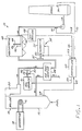
- the present invention is preferably used in conjunction with an apparatus 10 for precipitating particulate from a combustion gas stream, which is depicted in Figure 1.
- a coal-fired power plant coal is burned by a combustor 12, and the resulting hot flue or combustion gas is passed through a boiler 14, where it heats and boils water.
- the resulting steam in a loop 16 flows to a turbine/generator set 18, where electricity for consumption is produced.
- the steam is condensed, and the water flows back through the loop 16.
- the flue gas stream 20 leaving the boiler 14 cannot normally be exhausted directly to the atmosphere, because it contains the particulate or fly ash produced in the combustor 12. If it were exhausted to the atmosphere, the fly ash would contaminate the environment. Fortunately, the fly ash can be largely removed from the flue gas stream 20 by electrostatic precipitator technology, if the fly ash has a proper electrical resistivity and the proper physical characteristics.
- the fly ash produced by some types of coal particularly many coals containing a low sulfur content, has too high an electrical resistance to be processed in a collection device such as an electrostatic precipitator, and therefore must be conditioned before entering the precipitator. It is known to inject conditioning agents into the combustion gas stream, as illustrated schematically in Figure 1.
- a first conditioning apparatus 30 injects a first conditioning agent (that may be a gas, a liquid, or a solid, but is preferably a gas) into the flue gas stream 20.
- the first conditioning agent is preferably sulfur trioxide (SO3).
- the preferred first conditioning apparatus 30 therefore includes a source 31 of sulfur trioxide, and a plurality of sulfur trioxide injector nozzles 32 that extend into the flue gas stream 20 to inject the sulfur trioxide directly into the stream 20.
- a flow control device 33 such as a valve that controls the flow of sulfur or other feedstock for producing sulfur trioxide, meters the conditioning gas into the combustion gas stream 20 through the nozzles 32.
- a preferred source 31 is disclosed in US patent 3,993,429, and a preferred construction of the nozzles 32 is disclosed in US patent 4,179,071. The disclosures of both of these patents are incorporated herein by reference.
- the injected sulfur trioxide reacts with moisture in the gas stream 20, and the resulting sulfuric acid deposits upon the particulate in the gas stream to increase its conductivity, or, alternatively stated, to lower its resistivity. More specifically, the sulfur trioxide reacts with the residual moisture in the flue gas stream to form sulfuric acid on the surface of the particulate, which increases the electrical conductivity of the particulate.
- the flue gas 20 optionally passes through an air preheater 38, which is a heat exchanger that removes heat from the flue gas stream and heats the air that is used to burn the fuel in the combustor 12.
- an air preheater 38 which is a heat exchanger that removes heat from the flue gas stream and heats the air that is used to burn the fuel in the combustor 12.
- the sulfur trioxide conditioning agent is injected upstream of the air preheater 38, where the temperature of the flue gas is typically about 400°C.
- a second conditioning agent preferably ammonia
- a second conditioning apparatus 34 for adding ammonia gas includes a source 35 for the gas, a valve 36 that regulates the flow of the gas, and an injector 37 of the same general type as the injector 32.
- the ammonia source 35 is preferably simply a tank of liquid ammonia with a heater to gasify the required amount of liquid, and ammonia is not formed by reaction at the site of the power plant.
- the precipitator 40 may be of any of the many types commercially available and known in the art.
- the precipitator 40 includes a plurality of electrodes 42 charged with a high voltage, and grounded precipitation plates 44.
- the particulate in the gas stream 20 is charged by the electrostatic field established between the electrodes 42 and the plates 44, and is attracted to be deposited as a layer of dust 46 upon the plates 44 for subsequent removal.
- the layer 46 When the layer 46 becomes so thick that its electrical resistivity rises and prevents efficient further removal of the particulate, the layer 46 is removed by "rapping" by rapping hammers (not shown) that physically strike the plates 44 so that the particulate in the layer 46 falls into hoppers 47 below the plates 44. The plates are thereby cleaned and made ready for further collection of particulate.
- rapping hammers (not shown) that physically strike the plates 44 so that the particulate in the layer 46 falls into hoppers 47 below the plates 44.
- the plates are thereby cleaned and made ready for further collection of particulate.
- One particularly troublesome source of particulate in the flue gas leaving the electrostatic precipitator is particulate that is reentrained in the gas stream after having been precipitated electrostatically. Reentrainment can result from a fast moving flue gas stream, and typically is most severe during rapping.
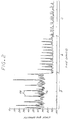
- Figure 2 is an exemplary graph of the measured opacity of the flue gas stream after it has left the electrostatic precipitator.
- the major spikes that occur periodically, indicated by numeral 78, are correlated to rapping events in the precipitator.
- the opacity level between the spikes, numeral 76, corresponds to the passthrough of particulate during normal operation of the electrostatic precipitator.
- Figure 2 illustrates the effect of adding conditioning agents.
- Figure 2(a) is the measured opacity as a function of time when no conditioning agents are added. The opacity between spikes in the steady state region 76 and the magnitude of the spikes 78 are both high.
- Figure 2(b) is the measured opacity when a small amount (here 5.5 parts per million) of sulfur trioxide is added to the flue gas stream. As compared with Figure 2(a), the addition of the sulfur trioxide reduces the steady state opacity between spikes, as desired, but the opacity spikes experienced during rapping are of roughly the same magnitude in excess of the steady state level as in the case of the unconditioned gas, Figure 2(a).
- Figure 2(c) is the measured opacity when a larger amount (here 17 parts per million) of sulfur trioxide is added to the flue gas stream and a substantial amount (here 17 parts per million) of ammonia is also added.
- the steady state opacity between spikes is reduced further as compared with Figures 2(a) and 2(b), and, significantly, the opacity spikes are greatly reduced in magnitude as compared with either Figure 2(a) or Figure 2(b).
- Proper additions of sulfur trioxide and ammonia can therefore have a beneficial effect upon the power plant emissions.
- electrostatic precipitator 40 including the voltage and current applied to the electrodes 42, the rapping of the plates 44 to cause the collected particulate to fall into hoppers, and auxiliary control and display functions are under the control of an electrostatic precipitator controller 48.
- the present invention relates to the control of the amount of conditioning agents added by the apparatus 30 and 34, to achieve the most acceptable combination of gaseous emission and particulate levels in the flue gas as it leaves the electrostatic precipitator and passes up the stack for release to the atmosphere.
- the following paragraphs provide a brief summary of the chemical and physical interactions resulting from the injection of the conditioning agents.
- ammonia injected by the second apparatus 34 reacts with the sulfur trioxide injected by the first apparatus 30, and water vapor in the flue gas stream 20, to produce ammonium bisulfate, NH4HSO4, or, under certain stoichiometric conditions, ammonium sulfate, (NH4)2SO4.
- the ammonia reaction therefore reduces the amount of sulfur trioxide available to deposit upon the particulate to reduce its resistivity.
- the ammonium bisulfate has a melting point of about 147°C, so that a melted layer of the ammonium bisulfate may be present upon the surface of the particulate, tending to reduce its electrical resistivity.
- ammonium bisulfate on the surface of the particulate may act in the manner of a binding agent, binding the particulate together in the electrostatic precipitator. This binding action desirably reduces the tendency for reentrainment of the particulate after deposition in the dust layer 46, and particularly during rapping, thereby reducing the emitted particulate in the stack gas.
- the ammonium sulfate can also have an effect upon the efficiency of the electrostatic precipitator by modifying the space charge within the collecting elements.
- a controller 60 receives feedforward and feedback signals indicative of the state of the flue gas stream 20, and adjusts the flow rates of the conditioning agents responsive to particular control procedures within the controller 60.
- the preferred feedforward signal is a boiler load signal 62, sent to the controller 60 from a boiler load sensor 64.
- the boiler load sensor 64 which is preferably a flow meter, measures the rate at which fuel is burned within the combustor 12, as a measure of the total volume or mass of flue gas and particulate that must be conditioned.
- the heat produced, the flow rate of flue gas, the flow rate of water in the boiler, the electrical output of the plant, or other acceptable factors could provide this indication of the total flue gas and particulate loading that must be conditioned.
- the power consumption of the electrostatic precipitator 40 is provided as a power consumption signal 66 from the electrostatic precipitator controller 48 to the injection controller 60.
- the power consumption of the electrostatic precipitator is the power, voltage times current, flowing between the electrodes 42 and the plates 44. Since electrostatic deposition fundamentally occurs by the conduction of charge by the particulate matter deposited in the layer 46, when more power is consumed by the precipitator 40, more particulate is removed from the flue gas stream 20.
- the power consumption of the electrostatic precipitator is a numerical value readily available from all modern commercial controllers 48, and therefore no new instrumentation is required.
- a second preferred feedback signal is the residual sulfur content of the flue gas after it has left the electrostatic precipitator 40.
- a residual gas content signal 68 is provided from a sensor 70 in the flue gas stream to the controller 60.
- the sulfur level may be measured in terms of a sulfur compound, such as sulfur dioxide or sulfur trioxide. If sulfur is present in several forms, normally the various levels are considered in a single reporting format.
- the residual sulfur content is the sulfur content, such as in parts per million by volume of the gas stream, that is emitted from the power plant into the atmosphere. Under existing environmental laws, there are strict limits on the residual sulfur content. Instruments for measuring the residual sulfur content, which may serve as the sensor 70, are commercially available. Examples of acceptable sensors 70 are the Severn Sciences Ltd.
- Model SSL/MEL for sulfur trioxide
- the Westinghouse Model EC 960 for sulfur dioxide.
- the residual ammonia content may also be measured by the sensor 70 and provided as part of the signal 68, and a suitable ammonia sensor is the Horiba Model C900.
- a suitable ammonia sensor is the Horiba Model C900.
- the proper amount of injected ammonia can react with excess sulfur trioxide to form an ammonium compound, removing the sulfur trioxide from the flue gas and preventing it from being emitted.
- a third preferred type of feedback signal is a stack gas opacity signal 72, which is measured by a stack gas opacity sensor 74 and provided to the controller 60.
- the sensor 74 measures the transmission of a beam of light through the stack gas (as the flue gas is termed after it leaves the electrostatic precipitator).
- the opacity is most directly responsive to the particulate level in the stack gas.
- Acceptable opacity analyzers that may be used as the sensor 74, are available commercially and include the Lear Siegler Model RM 41.
- the various feedforward and feedback signals are indicated in Figure 1 as being provided to the controller 60.
- the signals are provided automatically, as with a digital readout of the sensor or through an analog-to-digital conversion of an analog readout of the sensor. Equivalently, the signal can be hand-fed to the controller 60, as by typing in the signal value.
- An automatic input is preferred, as it permits the taking of many samples and building a statistical data base, without the need for human intervention.
- feedforward and feedback signals are utilized by the controller 60 to determine and control the optimum flow rates of the conditioning agents.
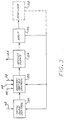
- the general procedure for the operation of the controller is illustrated in Figure 3.
- the feedforward signal 62 is provided to a total flow control function 120, which determines the total flow rates of each of the conditioning agents, in units such as pounds injected per unit time.
- the total flow control function 120 may be based upon a simple linear relation between boiler load and total flow rates, for example. Under such a linear relationship, if for example the total flow rate of flue gas in mass per unit time as measured by the feedforward signal 62 is doubled, the mass flow rate of conditioning agents in mass per unit time, injected by apparatus 30 and 34, is also doubled. More complex relationships may also be used, as appropriate for a particular power plant. That is, it may be known from experience that in certain operating regimes the relation between flow rate of conditioning agents and flow rate of flue gas is nonlinear, and this experience is programmed into the controller 60.
- the feedback signals 66, 68, and 72 are received by a concentration control function 122.
- the concentration control function 122 determines the required values of the operating flow concentration levels, in units such as parts per million, for the conditioning agents in the apparatus 30 and 34. The determination is based upon either theoretical or empirical relations between magnitudes of the control signals 66, 68, and 72, and required changes in one or more of the conditioning agents. Four specific preferred embodiments for the control procedures are discussed subsequently. Alternatively, the perturbation procedure described subsequently is used to establish operating relations.
- concentration flow rates in parts per million are converted by control function 122 to a mass flow of conditioning agents per unit time by multiplying by the mass flow of flue gas per unit time, which is known from the feedforward signal 62.
- the mass flows of conditioning agents per unit time are provided to the apparatus 30 and 34, in a manner to be described. (Of course, absolute values are not required, as relative mass flow signals to be sent to apparatus 30 and 34 are sufficient.)
- control function 122 includes the capability to introduce such delays where necessary. For example, depending upon the construction of a particular system, there may be a delay of as much as several hours between an increase in the sulfur trioxide injection concentration and an increase in one of the feedback signals whose origin can be traced to the increased sulfur trioxide injection. Such time delays are measured during initial calibration of the power plant and the control system, and incorporated into the programming.
- the operating flow levels of the conditioning agents are transmitted to the apparatus 30 and 34, and specifically the flow control devices 33 and 36, respectively, through a control cable 123, as indicated schematically at adjustment block 124.
- the controller then waits a predetermined time period, wait block 126, before repeating the procedure.
- wait block 126 the time period between adjustments is typically tens of minutes or hours.
- the sampling of the signals 62, 66, 68, and 72 may occur more frequently to build up a statistical basis for actions, but adjustments normally occur less frequently.
- Figure 3 shows in dashed lines a perturb block 128 that may be utilized in the control procedure. Because at this time there is not a complete scientific understanding of all of the chemical and physical interactions occurring in the system, it is not possible to know whether true optimum values of the flow rates of the conditioning agents have been reached, or whether a particular set of operating values may be a local optimum resulting from the nature of the interactions. In the future, some complete closed form or parametric understanding of the interactions may be discovered, but that is not available now. Therefore, to test the effect of changes in the flow rate of one of the conditioning agents upon the overall system performance, that flow rate can be forced to a value which the control functions 120 and 122 did not select.
- the control function 122 then adjusts the flow rate of the other conditioning agent responsive to the inputs 66, 68, and 72 that result from the perturbation. If the resulting performance in gaseous emission and particulate is improved, according to some figure of merit that is defined, then the perturb function judges that the new set of flow rates, resulting from the perturbation, is superior to the prior solution. If the performance is not improved, the flow parameters are returned to their prior values, possibly followed by perturbation in a different direction. In this manner, the controller 60 continually searches for better overall performance relationships.
- the controller 60 is preferably a digital microcomputer. It is programmed with the procedures depicted in Figure 3, and with control algorithms of the type to be discussed next. It also stores calibration data for the particular plant. As discussed previously, each power plant is unique, and there can be no optimal values specified that will be valid for all plants. Instead, a major advantage of the present approach is that it is adaptive. Plant calibration data that is determined from initial calibration testing and from actual operating results define the characteristics of the plant, and are stored in the computer. The procedures such as the perturbation function can add to this data base by providing the results of other operating conditions, and by improving the statistical certainty of the stored data. The controller thus learns as operating experience is gathered. For example, it may be initially assumed that the total flow rate of the conditioning agents should be linearly proportional to boiler load. Operating experience may instead show that there is a slight nonlinearity over some operating ranges, and that information is then added to the data base so that future adjustments benefit from the new information.
- control algorithms There are a wide variety of control algorithms that may be incorporated into the control functions 120 and 122 of the controller 60.
- the reason for this variety is that different feedback signal combinations can be used, and in some cases the system is overdetermined because there is more measured data available than required for the solution of two unknowns, the flow rates of the two conditioning agents.
- the availability of extra information is useful, because it facilitates the search for true optimal plant operating conditions, particularly where the power plant may have difficulty meeting only one of the emission and particulate limitations.
- four presently preferred embodiments utilizing different combinations of measured signals and control relationships are set forth, although many others can be envisioned.
- the conditioning agents are taken to be the preferred sulfur trioxide and ammonia gases.
- the total flow rate in mass per unit time of each of the conditioning agents is determined from the feedforward boiler load signal 62 and a linear relation or calibration curve for the plant.
- the ratio of the two conditioning agents is determined in one of four ways.
- a portion of the total flow of the sulfur trioxide and ammonia conditioning agents is established according to a preselected ratio.
- the preselected ratio is determined for the power plant during calibration as its best performance characteristic.
- a second portion of conditioning agents is added to these amounts, and typically the second portion is additional sulfur trioxide.
- the relative amount of the first portion is established responsive to the opacity signal 72, to minimize particulate loss to the stack gas.
- the relative amount of the second portion is established responsive to the electrostatic precipitator power consumption signal 66, to maximize that value.
- the relative amount of the second portion can also be controlled responsive to the residual sulfur signal 68, to minimize that value.
- the total flow rate of sulfur trioxide is adjusted responsive to the electrostatic power consumption signal 66 or the residual sulfur signal 68, as just described for the second portion under the first embodiment.
- the total flow rate of injected ammonia is adjusted to minimize the opacity signal 72, since the ammonia can increase the adherence of the particulate to resist reentrainment.
- the flow rate of ammonia is controlled in response to the opacity signal 72.
- the sulfur trioxide is adjusted according to a preset ratio with the ammonia.
- the sulfur trioxide and the ammonia flows can be adjusted independently, as long as the total flow of the conditioning agents is that required by the total flow computation based upon the feedforward signal.
- the functional operation of this embodiment will be described by way of illustration of the optimization and perturbation processes.
- the sulfur trioxide injection flow rate increases from below an optimum value, the power consumption of the electrostatic precipitator increases and the opacity spikes during rapping increase.
- the ammonia content can then be increased relative to the sulfur trioxide content, which reduces the effective sulfur trioxide content as a result of the ammonium bisulfate reaction.
- the precipitator power may decrease so that the total capture of particulate decreases, but at the same time the deposition of ammonium bisulfate on the particulate matter results in smaller opacity spikes during rapping.
- minima in emissions or optimal values can be discerned.
- the selected operating values may not be the mathematical joint minimal values, due to environmental laws that are more stringent for some emissions than for others and economic considerations such as the difficulty in selling recovered fly ash that is high in ammonia content.
- Such legal constraints are provided to the controller in the form of constraints or weighting factors for decision making.
- the perturbation function can optionally be used to intentionally change a flow rate away from the solution to ascertain the effect on the other flow rates.
- the system will find a new set of flow rates which may be even better than the prior solution, and the system then adopts that solution. If at a later time the feedforward signal changes, indicating a change, in total flue gas flow and thence particulate flow, the optimization procedure is repeated.
- Each optimal set of operating conditions is stored in the computer memory, and the control functions 120 and 122 check these values during optimization. In this way, prior experience is used to reduce the time needed to reach the best combination of conditioning agents for any particular operating conditions. The reduction in the search time to reach the desired combination reduces the time that the system operates in a non-optimal condition with higher emissions.
- the present invention thus provides a general apparatus and method for controlling the flow rates of additions of conditioning agents to flue gas streams of power plants. While general in form, the control process is particularized to an individual power plant, its operational characteristics, the type of coal used, and individual restrictions in the environmental laws, through calibration of the control system with actual power plant performance information.
Landscapes
- Engineering & Computer Science (AREA)
- Chemical & Material Sciences (AREA)
- Chemical Kinetics & Catalysis (AREA)
- General Chemical & Material Sciences (AREA)
- Health & Medical Sciences (AREA)
- Environmental & Geological Engineering (AREA)
- Biomedical Technology (AREA)
- Analytical Chemistry (AREA)
- General Engineering & Computer Science (AREA)
- Oil, Petroleum & Natural Gas (AREA)
- Mechanical Engineering (AREA)
- Treating Waste Gases (AREA)
- Electrostatic Separation (AREA)
Claims (29)
- Vorrichtung zum Regeln der Zugabe von Konditionierungsmitteln zu einem Partikel enthaltenden Abgasstrom, der durch einen Luftvorwärmer und danach durch einen Satz Abscheidungselektroden eines elektrostatischen Abscheiders strömt, bevor er in die Atmosphäre abgelassen wird, mit:
Mitteln zum Hinzugeben von mindestens zwei Konditionierungsmitteln, die mit dem Partikelmaterial im Abgas und miteinander chemisch reagieren, in den Strom des Abgases, wobei zumindest eines der Konditionierungsmittel in den Abgasstrom eingebracht wird, nachdem der Abgasstrom den Luftvorwärmer durchströmt hat, jedoch bevor er durch den Satz Abscheidungselektroden strömt;
einem Vorwärtsregelsensor, der das Abgas erfaßt und ein Vorwärtsregelsignal erzeugt, das die Menge der Strömungsrate des Partikelmaterials im Abgas vor der Zugabe der Konditionierungsmittel angibt;
einem Rückkopplungssensor, der das Abgas nach der Zugabe der Konditionierungsmittel erfaßt und ein Rückkopplungssignal erzeugt, das die physiochemische Wirkung der Zugabe der Konditionierungsmittel am Abgas/Partikelstromes angibt; und
einem Regler, der das Vorwärtsregelsignal und das Rückkopplungssignal erhält und die Mengen der Konditionierungsmittel, die dem Abgasstrom beigegeben werden, auf der Grundlage der Werte der Signale einstellt. - Vorrichtung nach Anspruch 1, die ferner einen zweiten Rückkopplungssensor aufweist, der das Abgas nach der Zugabe der Konditionierungsmittel erfaßt, und ein zweites dieses angebende Rückkopplungsignal erzeugt.
- Vorrichtung nach Anspruch 1, dadurch gekennzeichnet, daß der Vorwärtsregelsensor das Volumen des vom Abgas mitgenommenen Partikelmaterials mißt.
- Vorrichtung nach Anspruch 1, dadurch gekennzeichnet, daß der Vorwärtsregelsensor die Feuerungsrate der Verbrennungsvorrichtung mißt.
- Vorrichtung nach Anspruch 1, dadurch gekennzeichnet, daß der Rückkopplungssensor ein Schornsteingas-Opazitätsmonitor ist.
- Vorrichtung nach Anspruch 1, dadurch gekennzeichnet, daß der Rückkopplungssensor ein Restschwefeltrioxidmonitor ist.
- Vorrichtung nach Anspruch 1, dadurch gekennzeichnet, daß der Rückkopplungssensor ein Restammoniakmonitor ist.
- Vorrichtung nach Anspruch 1, dadurch gekennzeichnet, daß der Rückkopplungssensor die vom elektrostatischen Abscheider verbrauchte Leistung mißt.
- Vorrichtung nach Anspruch 1, dadurch gekennzeichnet, daß die Steuereinrichtung ein digitaler Mikrocomputer ist.
- Vorrichtung nach Anspruch 9, dadurch gekennzeichnet, daß der Mikrocomputer ein Instruktionsset besitzt, das die Gesamtstromrate der zugefügten Konditionierungsmittel in Abhängigkeit vom Vorwärtsregelsignal regelt.
- Vorrichtung nach Anspruch 10, dadurch gekennzeichnet, daß der Mikrocomputer ein Instruktionsset aufweist, das die relativen Mengen an zugegebenen Konditionierungsmittel in Abhängigkeit vom Rückkopplungssignal regelt.
- Vorrichtung nach Anspruch 1, dadurch gekennzeichnet, daß der Regler den Strom von mindestens einem der Konditionierungsmittel als diskontinuierlichen Strom einstellt.
- Vorrichtung nach Anspruch 12, dadurch gekennzeichnet, daß das Konditionierungsmittel, das diskontinuierlich strömt, Ammoniak ist.
- Vorrichtung nach Anspruch 1, dadurch gekennzeichnet, daß eines der Konditionierungsmittel Schwefeltrioxid ist.
- Vorrichtung nach Anspruch 1, dadurch gekennzeichnet, daß eines der Konditionierungsmittel Ammoniak ist.
- Verfahren zum Regeln der Zugabe von Konditionierungsmitteln zu einem Strom eines Abgases, das Partikelmaterial enthält, in einem Abgasreinigungssystem, mit einem Konditionierungsmittelinjektor, einem elektrostatischen Abscheider, zu dem das Abgas, nachdem das Konditionierungsmittel hinzugefügt ist, strömt, und einem Auslaß aus dem elektrostatischen Abscheider, welches Verfahren folgende Schritte aufweist:
Zugeben wenigstens zweier Konditionierungsmittel, die mit dem Partikelmaterial im Abgas und miteinander chemisch reagieren, zum Abgasstrom;
Erfassen des Abgases vor der Zugabe der Konditionierungsmittel und Vorsehen eines Vorwärtsregelsignals, das die Massenstromrate des Partikelmaterials im Abgas angibt;
Erfassen des Abgases nach der Zugabe der Konditionierungsmittel und Vorsehen eines Rückkopplungssignals, das die physiochemischen Wirkung der Zugabe der Konditionierungsmittel am Abgas/Partikelstrom angibt; und
Regeln der Mengen der Konditionierungsmittel, die dem Abgasstrom beigegeben werden, auf der Grundlage der Werte des Vorwärtsregelsignals und des Rückkopplungssignals. - Verfahren nach Anspruch 16, dadurch gekennzeichnet, daß der Schritt des Erfassens des Abgases vor der Zugabe des Konditionierungsmittels den Schritt des Messens der Boilerbelastung enthält.
- Verfahren nach Anspruch 16, dadurch gekennzeichnet, daß der Schritt des Erfassens des Abgases nach der Zugabe des Konditionierungsmittels den Schritt des Messens der Opazität des Abgases, nachdem es den elektrostatischen Abscheider verlassen hat, enthält.
- Verfahren nach Anspruch 16, dadurch gekennzeichnet, daß der Schritt des Erfassens des Abgases nach der Zugabe des Konditionierungsmittels den Schritt des Messens des Restschwefeltrioxidgehaltes im Abgas, nachdem es den elektrostatischen Abscheider verlassen hat, enthält.
- Verfahren nach Anspruch 16, dadurch gekennzeichnet, daß der Schritt des Erfassens des Abgases nach der Zugabe des Konditionierungsmittels den Schritt des Messens des Energieverbrauchs des elektrostatischen Abscheiders enthält.
- Verfahren nach Anspruch 16, dadurch gekennzeichnet, daß der Schritt des Erfassens des Abgases vor der Zugabe des Konditionierungsmittels den Schritt des Messens der Boilerbelastung enthält, und daß im Regelungsschritt die Gesamtströmungsrate der Konditionierungsmittel vom Rückkopplungssignal abhängig ist.
- Verfahren nach Anspruch 16, dadurch gekennzeichnet, daß die Konditionierungsmittel Schwefeltrioxid und Ammoniak sind.
- Verfahren nach Anspruch 22, dadurch gekennzeichnet, daß der Schritt des Erfassens des Abgases nach der Zugabe des Konditionierungsmittels den Schritt des Messens des Restschwefeltrioxidgehaltes im Abgas, nachdem es den elektrostatischen Abscheider verlassen hat, enthält, daß der Schritt des Erfassens des Abgases nach der Zugabe des Konditionierungsmittels den Schritt des Messens der Opazität des Abgases, nachdem es den elektrostatischen Abscheider verlassen hat, enthält,
daß der Schritt des Erfassens des Abgases nach der Zugabe des Konditionierungsmittels den Schritt des Messens des Energieverbrauchs des elektrostatischen Abscheiders enthält, und
daß in den Regelungsschritt die Strömungsrate des zugegebenen Ammoniak-Konditionierungsmittels von der Opazität des Abgases und die Strömungsrate des zugebenen Schwefeltrioxid-Konditionierungsmittels von Energieverbrauch des elektrostatischen Abscheiders und dem Restschwefeltrioxid abhängig ist. - Verfahren nach Anspruch 22, dadurch gekennzeichnet, daß der Schritt des Erfassens des Abgases nach der Zugabe des Konditionierungsmittels den Schritt des Messens der Opazität des Abgases, nachdem es den elektrostatischen Abscheider verlassen hat, enthält, und
daß in dem Regelungsschritt die Strömungsrate des zugebenen Ammoniak-Konditionierungsmittels von der Opazität des Abgases abhängig ist, und die strömungsrate des Schwefeltrioxids als eine Konstante mal der Strömungsrate des Ammoniak bestimmt ist. - Verfahren nach Anspruch 22, dadurch gekennzeichnet, daß der Schritt des Erfassens des Abgases vor der Zugabe des Konditionierungsmittels den Schritt des Messens der Boilerbelastung enthält,
daß der Schritt des Erfassens des Abgases nach der Zugabe des Konditionierungsmittels den Schritt des Messens des Restschwefelgehaltes im Abgas, nachdem es den elektrostatischen Abscheider verlassen hat, enthält, daß der Schritt des Erfassens des Abgases nach der Zugabe des Konditionierungsmittels den Schritt des Messens des Energieverbrauchs des elektrostatischen Abscheiders enthält, und
daß in dem Regelungsschritt die Gesamtstromrate der Konditionierungsmittel vom Boilerbelastungssignal und die Strömungsrate des zugebenen Schwefeltrioxid-Konditionierungsmittels vom Energieverbrauch des elektrostatischen Abscheiders und vom Restschwefeltrioxid abhängig ist. - Verfahren nach Anspruch 16, dadurch gekennzeichnet, daß zumindest eines der Konditionierungsmittel diskontinuierlich zugefügt wird.
- Verfahren nach Anspruch 26, dadurch gekennzeichnet, daß das Konditionierungsmittel, das diskontinuierlich zugefügt wird, Ammoniak ist.
- Verfahren nach Anspruch 16, dadurch gekennzeichnet, daß die beiden Konditionierungsmittel in den Abgasstrom an einem Ort zugeführt werden, nachdem das Abgas den Boiler verlassen hat; und
daß die Mengen an dem Abgasstrom zugefügten Konditionierungsmittel gesteuert werden durch Errichten des Gesamtstromes der Konditionierungsmittel in Abhängigkeit vom Vorwärtsregelsignal und Errichten des Verhältnisses der Konditionierungsmittel in Abhängigkeit vom Rückkopplungssignal. - Verfahren nach Anspruch 16, dadurch gekennzeichnet, daß die Konditionierungsmittel Schwefeltrioxid und Ammoniak sind.
Applications Claiming Priority (2)
| Application Number | Priority Date | Filing Date | Title |
|---|---|---|---|
| US523311 | 1990-05-14 | ||
| US07/523,311 US5029535A (en) | 1990-05-14 | 1990-05-14 | Control of addition of conditioning agents to flue gas |
Publications (2)
| Publication Number | Publication Date |
|---|---|
| EP0457225A1 EP0457225A1 (de) | 1991-11-21 |
| EP0457225B1 true EP0457225B1 (de) | 1995-09-06 |
Family
ID=24084493
Family Applications (1)
| Application Number | Title | Priority Date | Filing Date |
|---|---|---|---|
| EP91107684A Expired - Lifetime EP0457225B1 (de) | 1990-05-14 | 1991-05-11 | Regelung der Zugabe von Konditionierungsmitteln in Abgasen |
Country Status (7)
| Country | Link |
|---|---|
| US (1) | US5029535A (de) |
| EP (1) | EP0457225B1 (de) |
| AT (1) | ATE127365T1 (de) |
| AU (1) | AU631313B2 (de) |
| CA (1) | CA2042506A1 (de) |
| DE (1) | DE69112702D1 (de) |
| ES (1) | ES2080852T3 (de) |
Families Citing this family (35)
| Publication number | Priority date | Publication date | Assignee | Title |
|---|---|---|---|---|
| US5032154A (en) * | 1989-04-14 | 1991-07-16 | Wilhelm Environmental Technologies, Inc. | Flue gas conditioning system |
| US5350441A (en) * | 1990-03-15 | 1994-09-27 | Wilhelm Environmental Technologies, Inc. | Flue gas conditioning system |
| US5196038A (en) * | 1990-03-15 | 1993-03-23 | Wright Robert A | Flue gas conditioning system |
| PL168065B1 (pl) * | 1990-08-17 | 1995-12-30 | Fritz Schoppe | Sposób i urzadzenie do calkowitego suchego odsiarczania gazów spalinowych PL |
| ATE121311T1 (de) * | 1991-01-30 | 1995-05-15 | Stadt Landshut Vertreten Durch | Verfahren zur rauchgasreinigung von feuerungsanlagen, insbesondere müllverbrennungsanlagen. |
| US5176088A (en) * | 1992-01-10 | 1993-01-05 | The Babcock & Wilcox Company | Furnace ammonia and limestone injection with dry scrubbing for improved simultaneous SOX and NOX removal |
| US5240470A (en) * | 1992-04-07 | 1993-08-31 | Wilhelm Environmental Technologies, Inc. | In-duct flue gas conditioning system |
| US5288303A (en) * | 1992-04-07 | 1994-02-22 | Wilhelm Environmental Technologies, Inc. | Flue gas conditioning system |
| US5356597A (en) * | 1992-04-07 | 1994-10-18 | Wilhelm Environmental Technologies, Inc. | In-duct flue gas conditioning system |
| AU4278793A (en) * | 1992-04-07 | 1993-11-08 | Wilhelm Environmental Technologies, Inc. | Flue gas conditioning system |
| US5244642A (en) * | 1992-06-18 | 1993-09-14 | The Chemithon Corporation | Method for conditioning flue gas |
| DE4234163A1 (de) * | 1992-10-09 | 1994-04-14 | Siemens Ag | Schwel-Brenn-Verfahren sowie Schwel-Brenn-Anlage mit Drucksteuerung |
| US5567226A (en) * | 1992-10-09 | 1996-10-22 | Lookman; Aziz A. | Apparatus and method for enhancing the performance of a particulate collection device |
| US5370720A (en) * | 1993-07-23 | 1994-12-06 | Welhelm Environmental Technologies, Inc. | Flue gas conditioning system |
| USD364946S (en) | 1993-08-18 | 1995-12-05 | Stenovich Donald A | Emissions scrubber for wood burning units |
| DE4344112C2 (de) * | 1993-12-23 | 1998-10-22 | Metallgesellschaft Ag | Verfahren zur Steuerung der Sorptionsleistung eines Filtrationsabscheiders |
| US5553555A (en) * | 1994-04-28 | 1996-09-10 | Dasibi Environmental Corporation | System and method for flue gas purification for thermal power units |
| US5795548A (en) * | 1996-03-08 | 1998-08-18 | Mcdermott Technology, Inc. | Flue gas desulfurization method and apparatus |
| RU2123619C1 (ru) * | 1998-06-25 | 1998-12-20 | Белевич Алексей Игоревич | Парожидкостный струйный аппарат с давлением жидкости на выходе, превышающим давление рабочего газа |
| US6233526B1 (en) * | 1998-07-16 | 2001-05-15 | Micro Motion, Inc. | Vibrating conduit parameter sensors and methods of operation therefor utilizing spatial integration |
| US6093380A (en) * | 1998-10-16 | 2000-07-25 | Siirtec Nigi, S.P.A. | Method and apparatus for pollution control in exhaust gas streams from fossil fuel burning facilities |
| US6152053A (en) * | 1999-07-30 | 2000-11-28 | Abb Alstom Power Inc. | Method and assembly for converting waste water accumulated in a fossil fuel-fired power generation system |
| US20030143501A1 (en) * | 2002-01-31 | 2003-07-31 | Ferrigan James J. | Method and apparatus for sulfur trioxide flue gas conditioning |
| US7574968B2 (en) * | 2002-10-08 | 2009-08-18 | Energy & Environmental Research Center | Method and apparatus for capturing gas phase pollutants such as sulfur trioxide |
| US20040191709A1 (en) * | 2003-03-26 | 2004-09-30 | Miller Eric S. | Economizer bypass with ammonia injection |
| WO2004091796A2 (en) * | 2003-04-11 | 2004-10-28 | Stockhausen, Inc. | A reduced-emissions fossil-fuel-fired system |
| US8079845B2 (en) * | 2005-05-10 | 2011-12-20 | Environmental Energy Services, Inc. | Processes for operating a utility boiler and methods therefor |
| US20080267837A1 (en) * | 2007-04-27 | 2008-10-30 | Phelps Calvin E | Conversion of urea to reactants for NOx reduction |
| US8955763B2 (en) * | 2007-10-04 | 2015-02-17 | Consolidated Edison Company Of New York, Inc. | Building heating system and method of operation |
| US20100292934A1 (en) * | 2009-05-15 | 2010-11-18 | Baker Hughes Incorporated | Emissions analyzer and methods of using same |
| US9028751B2 (en) * | 2009-07-09 | 2015-05-12 | Odotech Inc. | System and method for dynamically controlling odor emission |
| US7931881B2 (en) * | 2009-09-25 | 2011-04-26 | Babcock Power Environmental Inc. | Integrated boiler and air pollution control systems |
| JP5260585B2 (ja) * | 2010-03-12 | 2013-08-14 | 株式会社日立製作所 | 石炭火力発電プラント及び石炭火力発電プラントの運転方法 |
| EP2834012A1 (de) * | 2012-04-04 | 2015-02-11 | ALSTOM Technology Ltd | Abgaskonditionierungssystem und verfahren |
| CN110652845A (zh) * | 2019-09-12 | 2020-01-07 | 常熟浦发第二热电能源有限公司 | 一种垃圾焚烧炉烟气脱酸反应塔前馈控制方法 |
Family Cites Families (7)
| Publication number | Priority date | Publication date | Assignee | Title |
|---|---|---|---|---|
| US3993429A (en) * | 1974-10-29 | 1976-11-23 | Wahlco, Inc. | Gas conditioning means |
| DE3430016A1 (de) * | 1984-08-16 | 1986-03-20 | Metallgesellschaft Ag, 6000 Frankfurt | Optimierung der Rauchgaskonditionierung |
| US4779207A (en) * | 1987-01-06 | 1988-10-18 | The Chemithon Corporation | SO3 flue gas conditioning system |
| FR2616241B1 (fr) * | 1987-06-02 | 1990-12-07 | Elf Aquitaine | Dispositif de regulation du fonctionnement d'une installation de traitements chimiques, pour ameliorer le rendement par attenuation des variances des parametres de reglage |
| US4793268A (en) * | 1987-11-27 | 1988-12-27 | Apollo Technologies Int'l | Method for controlling additive feed in a boiler system |
| US4872887A (en) * | 1988-09-12 | 1989-10-10 | Electric Power Research Institute, Inc. | Method for flue gas conditioning with the decomposition products of ammonium sulfate or ammonium bisulfate |
| ATE106768T1 (de) * | 1989-02-07 | 1994-06-15 | Ebara Corp | Reinigungsverfahren für auspuffgase. |
-
1990
- 1990-05-14 US US07/523,311 patent/US5029535A/en not_active Expired - Fee Related
-
1991
- 1991-05-11 ES ES91107684T patent/ES2080852T3/es not_active Expired - Lifetime
- 1991-05-11 AT AT91107684T patent/ATE127365T1/de not_active IP Right Cessation
- 1991-05-11 EP EP91107684A patent/EP0457225B1/de not_active Expired - Lifetime
- 1991-05-11 DE DE69112702T patent/DE69112702D1/de not_active Expired - Lifetime
- 1991-05-14 AU AU77047/91A patent/AU631313B2/en not_active Ceased
- 1991-05-14 CA CA002042506A patent/CA2042506A1/en not_active Abandoned
Also Published As
| Publication number | Publication date |
|---|---|
| EP0457225A1 (de) | 1991-11-21 |
| ATE127365T1 (de) | 1995-09-15 |
| US5029535A (en) | 1991-07-09 |
| AU631313B2 (en) | 1992-11-19 |
| CA2042506A1 (en) | 1991-11-15 |
| AU7704791A (en) | 1991-11-14 |
| ES2080852T3 (es) | 1996-02-16 |
| DE69112702D1 (de) | 1995-10-12 |
Similar Documents
| Publication | Publication Date | Title |
|---|---|---|
| EP0457225B1 (de) | Regelung der Zugabe von Konditionierungsmitteln in Abgasen | |
| McElroy et al. | Size distribution of fine particles from coal combustion | |
| US8644961B2 (en) | Model based control and estimation of mercury emissions | |
| EP0274132B1 (de) | S03-Konditionierungssystem für Abgase | |
| US5032154A (en) | Flue gas conditioning system | |
| McCain et al. | Results of field measurements of industrial particulate sources and electrostatic precipitator performance | |
| US5567226A (en) | Apparatus and method for enhancing the performance of a particulate collection device | |
| CA2532689C (en) | Method and apparatus for improving steam temperature control | |
| EP0450357B1 (de) | Regelungssystem zur Rauchgaskonditionierung | |
| US20030108470A1 (en) | Fly ash conditioning systems | |
| CN120522045B (zh) | 一种基于大数据的智能测控系统 | |
| CN117214056A (zh) | 电除尘器颗粒物浓度和运行电压精准预测及智能控制方法 | |
| Reese et al. | Experience with electrostatic fly-ash collection equipment serving steam-electric generating plants | |
| JPS5936559A (ja) | 電気集塵機の制御方法 | |
| Canadas et al. | Parametric testing of coal electrostatic precipitator performance | |
| Altman et al. | Resistivity conditioning of AFBC Generated Ash | |
| CN114067933B (zh) | 一种水泥sncr智慧运维方法及系统 | |
| Landreth | Advanced utility mercury-sorbent field-testing program | |
| CN212999110U (zh) | 一种烟气除尘系统及烟气除尘控制系统 | |
| Darby | Criteria for designing electrostatic precipitators | |
| Sparks et al. | Performance of a steam-ejector scrubber | |
| CN114662046A (zh) | 一种基于电厂实时数据的入炉煤硫分在线计算方法 | |
| Atkins et al. | Keeping fly ash out of the stack | |
| Kim et al. | Electrostatic precipitability of the coal fly-ash by the pilot scale test | |
| JPH11319478A (ja) | アンモニア注入装置 |
Legal Events
| Date | Code | Title | Description |
|---|---|---|---|
| PUAI | Public reference made under article 153(3) epc to a published international application that has entered the european phase |
Free format text: ORIGINAL CODE: 0009012 |
|
| AK | Designated contracting states |
Kind code of ref document: A1 Designated state(s): AT BE CH DE DK ES FR GB GR IT LI LU NL SE |
|
| 17P | Request for examination filed |
Effective date: 19920425 |
|
| 17Q | First examination report despatched |
Effective date: 19940323 |
|
| GRAA | (expected) grant |
Free format text: ORIGINAL CODE: 0009210 |
|
| AK | Designated contracting states |
Kind code of ref document: B1 Designated state(s): AT BE CH DE DK ES FR GB GR IT LI LU NL SE |
|
| PG25 | Lapsed in a contracting state [announced via postgrant information from national office to epo] |
Ref country code: IT Free format text: LAPSE BECAUSE OF FAILURE TO SUBMIT A TRANSLATION OF THE DESCRIPTION OR TO PAY THE FEE WITHIN THE PRE;WARNING: LAPSES OF ITALIAN PATENTS WITH EFFECTIVE DATE BEFORE 2007 MAY HAVE OCCURRED AT ANY TIME BEFORE 2007. THE CORRECT EFFECTIVE DATE MAY BE DIFFERENT FROM THE ONE RECORDED.SCRIBED TIME-LIMIT Effective date: 19950906 Ref country code: LI Effective date: 19950906 Ref country code: FR Effective date: 19950906 Ref country code: GR Free format text: LAPSE BECAUSE OF FAILURE TO SUBMIT A TRANSLATION OF THE DESCRIPTION OR TO PAY THE FEE WITHIN THE PRESCRIBED TIME-LIMIT Effective date: 19950906 Ref country code: NL Free format text: LAPSE BECAUSE OF FAILURE TO SUBMIT A TRANSLATION OF THE DESCRIPTION OR TO PAY THE FEE WITHIN THE PRESCRIBED TIME-LIMIT Effective date: 19950906 Ref country code: DK Effective date: 19950906 Ref country code: CH Effective date: 19950906 Ref country code: AT Effective date: 19950906 Ref country code: BE Effective date: 19950906 |
|
| REF | Corresponds to: |
Ref document number: 127365 Country of ref document: AT Date of ref document: 19950915 Kind code of ref document: T |
|
| REF | Corresponds to: |
Ref document number: 69112702 Country of ref document: DE Date of ref document: 19951012 |
|
| PG25 | Lapsed in a contracting state [announced via postgrant information from national office to epo] |
Ref country code: SE Effective date: 19951206 |
|
| PG25 | Lapsed in a contracting state [announced via postgrant information from national office to epo] |
Ref country code: DE Effective date: 19951207 |
|
| NLV1 | Nl: lapsed or annulled due to failure to fulfill the requirements of art. 29p and 29m of the patents act | ||
| EN | Fr: translation not filed | ||
| REG | Reference to a national code |
Ref country code: CH Ref legal event code: PL |
|
| REG | Reference to a national code |
Ref country code: ES Ref legal event code: FG2A Ref document number: 2080852 Country of ref document: ES Kind code of ref document: T3 |
|
| PG25 | Lapsed in a contracting state [announced via postgrant information from national office to epo] |
Ref country code: LU Free format text: LAPSE BECAUSE OF NON-PAYMENT OF DUE FEES Effective date: 19960531 |
|
| PLBE | No opposition filed within time limit |
Free format text: ORIGINAL CODE: 0009261 |
|
| STAA | Information on the status of an ep patent application or granted ep patent |
Free format text: STATUS: NO OPPOSITION FILED WITHIN TIME LIMIT |
|
| 26N | No opposition filed | ||
| PGFP | Annual fee paid to national office [announced via postgrant information from national office to epo] |
Ref country code: GB Payment date: 19980403 Year of fee payment: 8 |
|
| PGFP | Annual fee paid to national office [announced via postgrant information from national office to epo] |
Ref country code: ES Payment date: 19980522 Year of fee payment: 8 |
|
| PG25 | Lapsed in a contracting state [announced via postgrant information from national office to epo] |
Ref country code: GB Free format text: LAPSE BECAUSE OF NON-PAYMENT OF DUE FEES Effective date: 19990511 |
|
| PG25 | Lapsed in a contracting state [announced via postgrant information from national office to epo] |
Ref country code: ES Free format text: LAPSE BECAUSE OF NON-PAYMENT OF DUE FEES Effective date: 19990512 |
|
| GBPC | Gb: european patent ceased through non-payment of renewal fee |
Effective date: 19990511 |
|
| REG | Reference to a national code |
Ref country code: ES Ref legal event code: FD2A Effective date: 20010503 |