EP0456940B1 - Vorrichtung zum Wechseln von Werkzeugen und mit dieser Vorrichtung ausgerüstete Maschine - Google Patents
Vorrichtung zum Wechseln von Werkzeugen und mit dieser Vorrichtung ausgerüstete Maschine Download PDFInfo
- Publication number
- EP0456940B1 EP0456940B1 EP19900401268 EP90401268A EP0456940B1 EP 0456940 B1 EP0456940 B1 EP 0456940B1 EP 19900401268 EP19900401268 EP 19900401268 EP 90401268 A EP90401268 A EP 90401268A EP 0456940 B1 EP0456940 B1 EP 0456940B1
- Authority
- EP
- European Patent Office
- Prior art keywords
- tool
- axis
- assembly
- pressing
- support member
- Prior art date
- Legal status (The legal status is an assumption and is not a legal conclusion. Google has not performed a legal analysis and makes no representation as to the accuracy of the status listed.)
- Expired - Lifetime
Links
- 238000003825 pressing Methods 0.000 claims description 72
- 238000006073 displacement reaction Methods 0.000 claims description 18
- 230000000295 complement effect Effects 0.000 claims description 17
- 239000000463 material Substances 0.000 claims description 16
- 230000009471 action Effects 0.000 claims description 12
- 239000012530 fluid Substances 0.000 claims description 12
- 230000000694 effects Effects 0.000 claims description 7
- 238000010521 absorption reaction Methods 0.000 claims description 4
- 230000005484 gravity Effects 0.000 claims description 4
- 230000000903 blocking effect Effects 0.000 claims 1
- 238000013519 translation Methods 0.000 description 18
- 230000008859 change Effects 0.000 description 11
- 208000031968 Cadaver Diseases 0.000 description 8
- 238000000605 extraction Methods 0.000 description 5
- 239000004753 textile Substances 0.000 description 5
- 239000000835 fiber Substances 0.000 description 4
- BASFCYQUMIYNBI-UHFFFAOYSA-N platinum Chemical compound [Pt] BASFCYQUMIYNBI-UHFFFAOYSA-N 0.000 description 4
- 230000003042 antagnostic effect Effects 0.000 description 3
- 238000013461 design Methods 0.000 description 3
- 230000014759 maintenance of location Effects 0.000 description 3
- 230000008021 deposition Effects 0.000 description 2
- 238000012423 maintenance Methods 0.000 description 2
- 238000000034 method Methods 0.000 description 2
- 101100536354 Drosophila melanogaster tant gene Proteins 0.000 description 1
- 241001080024 Telles Species 0.000 description 1
- 230000004308 accommodation Effects 0.000 description 1
- 230000008878 coupling Effects 0.000 description 1
- 238000010168 coupling process Methods 0.000 description 1
- 238000005859 coupling reaction Methods 0.000 description 1
- 238000013016 damping Methods 0.000 description 1
- 230000007547 defect Effects 0.000 description 1
- 238000003754 machining Methods 0.000 description 1
- 238000012986 modification Methods 0.000 description 1
- 230000004048 modification Effects 0.000 description 1
- 230000008569 process Effects 0.000 description 1
- 230000000284 resting effect Effects 0.000 description 1
- 230000008961 swelling Effects 0.000 description 1
- 238000012546 transfer Methods 0.000 description 1
- 238000004804 winding Methods 0.000 description 1
- 210000002268 wool Anatomy 0.000 description 1
Images



Classifications
-
- B—PERFORMING OPERATIONS; TRANSPORTING
- B30—PRESSES
- B30B—PRESSES IN GENERAL
- B30B15/00—Details of, or accessories for, presses; Auxiliary measures in connection with pressing
- B30B15/02—Dies; Inserts therefor; Mounting thereof; Moulds
- B30B15/028—Loading or unloading of dies, platens or press rams
-
- B—PERFORMING OPERATIONS; TRANSPORTING
- B23—MACHINE TOOLS; METAL-WORKING NOT OTHERWISE PROVIDED FOR
- B23Q—DETAILS, COMPONENTS, OR ACCESSORIES FOR MACHINE TOOLS, e.g. ARRANGEMENTS FOR COPYING OR CONTROLLING; MACHINE TOOLS IN GENERAL CHARACTERISED BY THE CONSTRUCTION OF PARTICULAR DETAILS OR COMPONENTS; COMBINATIONS OR ASSOCIATIONS OF METAL-WORKING MACHINES, NOT DIRECTED TO A PARTICULAR RESULT
- B23Q3/00—Devices holding, supporting, or positioning work or tools, of a kind normally removable from the machine
- B23Q3/155—Arrangements for automatic insertion or removal of tools, e.g. combined with manual handling
- B23Q3/1556—Arrangements for automatic insertion or removal of tools, e.g. combined with manual handling of non-rotary tools
- B23Q3/15566—Arrangements for automatic insertion or removal of tools, e.g. combined with manual handling of non-rotary tools the tool being inserted in a tool holder directly from a storage device, i.e. without using transfer devices
-
- B—PERFORMING OPERATIONS; TRANSPORTING
- B25—HAND TOOLS; PORTABLE POWER-DRIVEN TOOLS; MANIPULATORS
- B25J—MANIPULATORS; CHAMBERS PROVIDED WITH MANIPULATION DEVICES
- B25J15/00—Gripping heads and other end effectors
- B25J15/04—Gripping heads and other end effectors with provision for the remote detachment or exchange of the head or parts thereof
- B25J15/0491—Gripping heads and other end effectors with provision for the remote detachment or exchange of the head or parts thereof comprising end-effector racks
-
- B—PERFORMING OPERATIONS; TRANSPORTING
- B30—PRESSES
- B30B—PRESSES IN GENERAL
- B30B15/00—Details of, or accessories for, presses; Auxiliary measures in connection with pressing
- B30B15/02—Dies; Inserts therefor; Mounting thereof; Moulds
- B30B15/026—Mounting of dies, platens or press rams
-
- B—PERFORMING OPERATIONS; TRANSPORTING
- B30—PRESSES
- B30B—PRESSES IN GENERAL
- B30B9/00—Presses specially adapted for particular purposes
- B30B9/30—Presses specially adapted for particular purposes for baling; Compression boxes therefor
- B30B9/3003—Details
- B30B9/3021—Press rams
-
- B—PERFORMING OPERATIONS; TRANSPORTING
- B65—CONVEYING; PACKING; STORING; HANDLING THIN OR FILAMENTARY MATERIAL
- B65B—MACHINES, APPARATUS OR DEVICES FOR, OR METHODS OF, PACKAGING ARTICLES OR MATERIALS; UNPACKING
- B65B27/00—Bundling particular articles presenting special problems using string, wire, or narrow tape or band; Baling fibrous material, e.g. peat, not otherwise provided for
- B65B27/12—Baling or bundling compressible fibrous material, e.g. peat
Definitions
- the invention relates to a device for changing at least one tool that can be dismantled along a preferred axis with a support member that is mobile at least in translation in a direction substantially parallel to the assembly axis with the 'tool.
- the invention relates to a device of the aforementioned type, more particularly but not exclusively, for equipping an automatic machine with a view to pressing and then strapping substantially cylindrical packages of textile material which are delivered to the machine in at least two diameters different.
- strapping means any method of laying ties around the pressed packet.
- the fibers are assembled into wicks of very long lengths which are deposited by gravity in spiral layers in receptacles each generally cylindrical of revolution and vertical axis.
- the fiber bundles are given different diameters and commonly diameters of 400, 600, 700 or 800 millimeters.
- the pressing-strapping machines which have been mentioned above are used precisely to compact the aforementioned bundles of fibers with a view to their transport and / or their storage under a reduced volume.
- the receptacles in which the packages are made up, are conventionally brought in turn into at least one such pressing-strapping machine.
- each of the packets is pressed along an axis substantially coincident with that of the longitudinal of the receptacle which contains it and between, on the one hand, a member which materializes the bottom of the receptacle and, on the other hand, a tool which comes to rest on the upper free face of the package.
- the pressing tool is associated with a member movable in translation along the longitudinal axis of the receptacle.
- the member which constitutes the bottom of the receptacle is axially movable at said receptacle and, on the other hand, after the pressing tool has been brought into contact with the upper surface of the package, we move in synchronism and in the same direction the two antagonistic elements that are the pressing tool and the bottom of the receptacle so as to extract the package from its receptacle, after which, by bringing the two antagonistic elements together, the package is pressed and then at the end pressing, we put the cerclase around the package.
- the movable member which constitutes the bottom of the receptacle is implicitly adapted to the diameter of said receptacle, on the other hand, that of the pressing tool is not.
- the machine can accommodate receptacles of different diameters so as not to have to change the pressing tool manually, obviously, the machine must be equipped with a tool changing device, preferably acting automatically.
- Devices of this type use at least one circular plate which, with indexed rotation about a given axis, on the one hand, carries means for housing a plurality of tools and, on the other hand, is placed under the effect of a means of displacement in translation in a direction substantially perpendicular to its axis of rotation so as to be movable between two positions including a position allowing the change of tools and a position releasing the working area of the tool taken from one of the tool housing means which it comprises.
- the context of use of the pressing machines is such that it is necessary to reconcile very limiting parameters such as the overall size of the device, the speed of tool change, the reliability of the operation, which prohibits the use direct from a device of the aforementioned type.
- One result which the invention aims to obtain is precisely a tool changing device which overcomes the aforementioned drawbacks.
- the subject of the invention is a device for changing tools according to the text of claim 1.
- a machine 1 for pressing and then strapping substantially cylindrical packages 2 of textile material 3 which are delivered to the machine in at least two different diameters and, for example, in three different diameters.
- the packages 2 of textile material 3 are delivered to the machine 1, each contained in a receptacle 4 substantially cylindrical of revolution which, on the one hand, is oriented with its longitudinal axis 5 approximately vertical and, on the other hand, includes an opening 6 at its upper part 7.
- each receptacle comprises a bottom 8 which is axially movable at said receptacle, in order, as has been explained above, to allow the material pack to be extracted before it is pressed.
- the machine comprises, at station 9 where the pressing must take place, which therefore is said to be pressing station 9, means 10 for translational movement of the bottom 8 of the receptacle at least up to the level of the upper opening 6 of said receptacle.
- the displacement means 10 mentioned consists of a double-acting cylinder whose end 10a of the rod is associated with the bottom 8 by a coupling means 10b with controlled locking.
- the machine comprises at least one tool 11 intended to be brought into contact with the upper free face 12 of the packet 2 of material contained in each receptacle which is brought to the pressing station.
- This pressing tool 11 is associated with a member 13 movable in translation relative to the frame 14 of the machine and this along an axis 15 approximately coincident with that longitudinal 5 of the receptacle located at the pressing station.
- the member 13 mentioned consists of the end of the rod 16 of a double-acting cylinder 17.
- each pressed packet must be encircled in the axially compressed position, in particular between the pressing tool 11 and the bottom 8 of the receptacle.
- the tool which must come into contact with the free face 12 of the package 2 conventionally has in a plane orthogonal to the axis 5 of the receptacle, on the one hand, a diameter substantially smaller than that inside of said receptacle and , on the other hand, as continuous a surface as possible.
- the body of the tool is, at its free end, extended by a nose 11a for centering the material pack prior to pressing.
- this nose 11a makes it possible to limit the pressing of the package.
- the machine shown comprises at least one device 31 for changing the pressing tools 11.
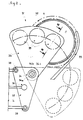
- the plate 33 is carried by an element 37 on which it is articulated by the means 34 for this purpose, along the articulation axis 34a defined and this under the influence of the means 36 of controlled movement also defined and, on the other hand, this element 37 is not only associated with the frame 14 of the machine by means 38 for guiding in translation along an axis 38a approximately parallel to that of assembly 32a of the tool with the tool support member, but also placed under the influence of a displacement means 39 controlled along the axis 32a considered, this means having a displacement amplitude at least sufficient to allow, both the assembly with the member support 13 of any pressing tool 11 of the aforementioned type carried by one of the means 35 for housing the plate 33 which is located opposite the support member 13 that, at the end of this assembly, the total clearance of the tool 11 of the housing means 35 which carried it so re to allow the erasure of the plate 33 of the pressing station 9.
- the tool change device of the aforementioned type occupies only a volume barely larger than that of all of the tools it comprises.
- the machines of the aforementioned type each comprise a frame essentially comprising a base and an upper plate between which are interposed columns which give wide access to the pressing devices.
- the tool change device considered is reliable since it uses very few mechanical elements and it is also precise since practically only angular indexing is required during articulation of the plate.
- the aforementioned means 38, 39 for guiding and moving in translation are not strictly necessary because the tool support member 13 is movable in translation and could therefore come to seek and / or deposit any tool 11 in a means 35 of housing located opposite.
- the means 39 for translational movement of the plate consists of a jack, its section being objectively less than that of the pressing jack 17, the speed of movement of its piston is much higher if the same source is used pressurized fluid to control it, which has a significant effect on the length of the tool change cycle.
- the means 38 for guiding the plate in translation consists of a plurality of guide columns with ball bearings, the columns being integral with the frame and the sleeves of the element carrier 37.
- the means 34 of articulation of the plate comprises for example a stepped shaft 34b which, integral with the plate, is supported and guided in a sheath 34c secured to the carrier element 37 linked to the frame 14.
- the means 36 for controlled movement of the plate around the hinge axis 34a advantageously consists of a gear motor carried by the element 37 on which the plate is supported and which drives at least indirectly a pinion secured to the shaft of the articulation means of said plate 33.
- This plate 33 is preferably constituted by a plate in the form of a circular sector, the top of which cooperates with the articulation means 34 and on which are juxtaposed in particular substantially in an arc, the means 35 for housing the pressing tools.
- each of the housing means 35 and each of the pressing tools 11, in particular in their part intended to cooperate with a housing means 35 comprise complementary bearing surfaces 40 to 43 which define at least one axis said centering 44 substantially coincident with that 22 longitudinal of a body 21 of the tool and ensure stable maintenance of the tool in the assembly position with the support member.
- each housing means 35 is associated with the plate 33 by means of at least one means 45 for elastic absorption of the displacements which are imparted to it during assembly and / or the deposition of a tool, that is to say displacements resulting from a possible defect in positioning of the means considered with respect to the tool support member 13 and / or those which may result from the fall of a tool in this accommodation.
- each housing means 35 comprises a generally tubular body intended to at least partially accommodate the tool and in which body are arranged the bearing surfaces 42, 43 complementary to those 40, 41 of the tool and this body is freely engaged in a cutout 46 provided in the plate 33 and is supported on the latter by the means 45 of elastic absorption.
- the absorption means 45 is for example made up of a plurality of radially distributed damping blocks 45a interposed between a flange 47 secured to the body of the housing means and a face opposite the plate 33.
- At least some of the arms 25 of each tool comprise at least one surface 40a which, generally opposite to that 40b which must come into contact with the material to be pressed, constitutes, in the arm rest position, a portion of at least one of the bearing surfaces 40, 41 that the tool includes.
- This technical feature makes it possible to constrain the arms in the rest position and therefore to avoid any incident due to the movement of the arms by inertia, in particular during the articulation of the plate.
- the aforementioned surfaces 40a each determine a portion of conical surface 40 of revolution centered on the longitudinal axis of the body of the tool and, to cooperate with these portions 40a, the body of the housing means comprises a complementary conical bearing 42 as for it substantially continuous.
- At least one other conical bearing 41 is provided on the body of the tool and, at least on the body of the housing means complementary conical bearing 43.
- the assembly element 20 associated with the support member 13 consists of a shaft 20 whose end opposite 20a has at least one bearing 20b, 20c for centering and longitudinal support for the complementary assembly element 19 associated with the tool, this assembly element consisting in turn of a sheath intended to fit onto the shaft and which at its end intended to be associated with the tool, internally comprises at least one bearing 19b, 19c complementary to those 20b, 20c of the shaft and on the other hand, the shaft 20 comprises at level of its end 20d associated with the support member, at least one means 20th radially expandable against a 19th conical bearing produced in the sheath and oriented to induce the locking of the assembly, that is to say the bearing support of the bearing complementary 19b, 1 9c, 20b, 20c of the sheath 19 and the shaft 20.
- the jack 17 is oriented substantially vertically with the end 13 of the rod 16 facing the ground S and therefore the tool 11 which it carries is subjected to gravity.
- the assembly means 32 must therefore preserve the connection between the tool 11 and the end of the rod in the absence of power supply energy to the machine 1.
- the radially expandable means 20e comprises, on the one hand, a plurality of pieces 20f resting on the conical surface 19e of the sleeve 19, these pieces being energetically stressed at least indirectly by at least one elastic member 20g in their direction of application on the aforementioned 19th conical bearing and, on the other hand, at least one 20h controlled motor member whose action is opposite to that of each elastic member 20g so as to allow at least the retraction of the means 20th expandable under the effect of the displacement of the tool that gravity tends to induce.
- This technical feature therefore makes it possible to obtain the desired result since the locking of the tool in the assembled position is induced by an elastic member.
- the pressing tool 11 comprises a means 30b for controlling the arms 25 between the rest position and the pressing position and for elastic retention in the latter position.
- this control means 30b consists of a piston 30b which, moved in a bore 30c of the body 21 of the tool, under the action of a fluid under pressure, acts on the end of the arms 25 close to their articulation at tool body so as to induce the maintenance of said arms in the pressing position.
- the assembly means 32 comprises at least one channel 20p.
- the channel 20p opens into the control chamber of the piston 30b of the tool 11.
- the channel 20p is arranged mainly axially by means of assembly 32 and therefore through the piston 20h for locking the assembly means 32 and it must therefore not interfere with the circuit of pressurized fluid which must control this piston .
- the piston 20h of the assembly means 32 is, at least at its face 20o which must receive the action of a pressurized fluid, traversed by a spindle 20q itself traversed by the channel 20p d routing of the pressurized fluid to the tool 11, which spindle is, on the one hand, carried by the face 20n of the axial bore 20j turned towards the face considered 20n of the piston and, on the other hand, connected in a manner leaktight and slidably mounted over a length at least equal to the amplitude of displacement of the piston considered in a bore 20r connected to the channel 20p for conveying a pressurized fluid towards the pressing tool 11.
- the axially compressed package must, during the strapping, be stepped driven around its longitudinal axis to allow the fitting of the strapping 18 in planes generally parallel to said longitudinal axis.
- the assembly means 32 is firstly associated with the end of the cylinder rod by means of a guide for rotation and obviously stop in translation along an axis approximately coincident with that of translation of the jack and on the other hand receives the action of a control means in fractional rotation.
- the guide means is for example a ball bearing.
- the means for controlling the rotation step by step it comprises for example a crown associated with the shaft 19 of the assembly means and a pinion in turn associated with a shaft for controlling the rotation.
- the supply of the pressurized fluid circuits internal to the shaft of the assembly means is in particular carried out by means of rotary joints.
- the machine equipped with the tool changing device 31 comprises a mechanical assembly 48 for strapping the packages, for example by tying with a string 18.
- this ligating assembly comprises an arm 48a for driving the twine around the packet of pressed material.
- this assembly comprises a head 48b known as knotting and which, precisely, knots between them the two ends of the twine wrapped around the packet, and this obviously when the winding is finished.
- the binding assembly 48 in order to make it possible to adapt not only the position of the drive arm 48a but also that of the knotting head 48b as a function of the diameter of the pressed packet, the binding assembly 48, d firstly, is supported by the frame of the machine by at least two means 49, 50 for guiding in translation in directions substantially perpendicular and in a plane generally orthogonal to the axis of translation 15 of the jack 17 tool support 11 and, on the other hand, each of the aforementioned guide means is associated with a motor means 49a, 50a controlled for the purpose of moving the ligating assembly in each of the defined directions, these motor means being controlled by a control means 51 for controlled by a means 52 for detecting the diameter of the pressed packet.
- the tool changing device is arranged substantially symmetrically with the mechanical strapping assembly with respect to the axis of translation 15 of the support member.
- the above-mentioned machine also comprises means 53 for conveying the receptacles to the pressing station 9.
- the routing means 53 consists of a turntable in a substantially horizontal plane, between the pressing station 9 and the receiving station 54 for the receptacles which comprises the machine and which is diametrically opposite to it.
- the means 52 for detecting the diameter of the pressed packet is for example a means for detecting the diameter of the receptacle from which the packet of material will be extracted and advantageously this means is located on the path of the receptacles between the reception station 54 and the station pressing 9 so that, during the ejection of the container emptied of its contents by a means 55 for this purpose, we can if necessary anticipate the change of tool.
- the turntable 53 is equipped with a motor means 56 controlled to drive in rotation.
- the cycle considered begins after the means 55 provided for this purpose has ejected the receptacle from the packet which has been processed.
- the rod of the jack 10 which must cooperate with the bottom 8 of the receptacle 4 is retracted in the retracted position so as to allow the transfer to the pressing station of a receptacle containing a packet of material to be pressed by rotation of the plate 53 .
- the pressing tool 11 which equips the support member which has just been, if necessary, be released from the packet of pressed and ligated material does not correspond to the diameter of the receptacle transferred to the pressing station, we change the tool to replace it with a tool of diameter adapted to the package in question.
- the housing means 35 reserved for this tool is brought by articulation of the plate opposite said tool, then, the plate is translated upwards so as to fit this said means onto the tool in question;
- the unlocking of the assembly means is controlled then, the plate is translated into the low position, after which, by articulation of said plate, the tool suitable for pressing the package located at the pressing station is brought to l plumb of the support member.
- the plate is again translated upwards then downwards when the assembly is carried out after which it is the total erasure of said plate which is controlled.
- the translation of the bottom of the receptacle located at the pressing station can be controlled for the extraction of the package.
- the member which constitutes the bottom of the receptacle is coupled to the rod of the jack which will control its movement.
- the receptacle is then energetically maintained on its support plane by means 57 provided for this purpose and this retention is preserved at least during the entire phase of extraction of the package from the receptacle .
- the pressing tool Prior to the extraction of the material packet and / or at least when the free face of the packet appears in the plane of the opening of the receptacle, the pressing tool is lowered in abutment on said free face.
- pressing can begin and preferably, the displacement of the opposing jacks, one carrying the pressing tool, the other the member which constitutes the bottom of the receptacle brings the pressed packet into the binding position.
- the motor means associated with the means for guiding in translation of the knotting assembly having corrected the position of this assembly, the tying can be carried out.
- the jack which carries the bottom of the receptacle is retracted and the articulated arms of the member which constitutes the bottom, in order to escape the ligatures, then counteract the action of the elastic means 30a which maintains them in the so-called position pressing.
- the said receptacle is evacuated.
- the pressing tool must be released from the pressed-ligated package and, for this purpose, after having released the action of holding these arms in the pressing position, the package is ejected by means a pusher 58.
- the pressed bundle ligated is for example collected on a plate 59 previously placed at the point of fall of the bundle.
- the arms of the pressing tool are either left in the rest position, in particular if this tool has to be replaced, or returned to the pressing position.
Landscapes
- Engineering & Computer Science (AREA)
- Mechanical Engineering (AREA)
- Robotics (AREA)
- Automatic Assembly (AREA)
- Basic Packing Technique (AREA)
Claims (7)
- Vorrichtung (31) zum Wechseln mindestens eines Werkzeugs (11, das abnehmbar entlang einer bevorzugten Achse (32a), insbesondere der sogenannten Montageachse (32a), einem Trägerelement (13) zugeordnet ist, welches seinerseits zumindest translatorisch in einer im wesentlichen parallelen Richtung (15), der sogenannten Montageachse des Werkzeugs, beweglich ist, wobei die Vorrichtung vor allem dem Rahmen (14) einer Preßmaschine (1) zugeordnet ist, und wobei das in Frage stehende Werkzeug folgendes aufweist:- einen im großen und ganzen zylinderförmigen Mittelkorpus (21) in Form eines umhüllenden Drehkörpers mit einer Längsachse (22), der an einem (23) seiner Enden (23, 24) ein abnehmbares Montageteil (19) mit einem komplementären Teil (20) trägt, das seinerseits auf einem Trägerelement (13) gelagert ist, mit welchem es eine Einrichtung (32) zur Montage unter Verriegelung bildet, die zur Montage entlang einer zur Translationsachse (15) des Trägerelements (13) beim Preßvorgang in etwa parallelen Achse ansteuerbar ist,
eine dem gegenüberliegenden Ende (24) des Korpus zugeordnete Vielzahl langgestreckter Arme (25), die einerseits insbesondere über ein freies (26) ihrer Enden (26, 27) in Ebenen angelenkt sind, die im wesentlichen radial zur Längsachse (22) des Korpus und in regelmäßigen Abständen um diese Achse verteilt und andererseits zwischen zwei Positionen (28, 29) beweglich sind, von denen zumindest eine die Endstelluns (28), die sogenannte Preßstellung, ist in welcher sie in einer Ebene verlaufen, die in etwa senkrecht zur Längsachse (22) des Korpus (21) verläuft, und die andere Position (29) die sogenannte Ruhelage ist, in welcher sie im wesentlichen parallel zur selben Längs- achse verlaufen und insbesondere über das Ende des Korpus überstehen, an welchem sie angelenkt sind,
wobei diese Vorrichtung ihrerseits mindestens eine zumindest indirekt auf dem Rahmen (14) der Maschine mittels einer hierzu vorgesehenen Einrichtung (34) entlang einer Achse (34a) angelenkte Halteplatte aufweist, die im wesentlichen parallel zur genannten Montageachse (32a) verläuft, wobei die Halteplatte:- einerseits eine Vielzahl von Lagereinrichtungen (35) trägt; und zwar jeweils eine für eines der Werkzeuge (11) mit dessen Korpus (21) in einer Position ähnlich derjenigen, die beim Zusammenbau mit dem Trägerelement entlang der Montageachse (32a) einzunehmen ist, wobei die Lagereinrichtungen (35) eine Lage bezüglich der Anlenkachse und eine Winkelstellung um diese Achse in der Weise haben, daß durch Anlenkung der Trägerplatte jede der Lagereinrichtungen (35) in eine Stellung gegenüber dem Trägerelement (13) so führbar ist, daß ein Werkzeug (11) entlang der definierten Montageachse (32a) ablegbar und/oder ergreifbar ist,- und wobei diese Einrichtung andererseits unter entsprechender Zuordnung zu mindestens einer Einrichtung (36), die zur Verlagerung um ihre Anlenkachse (34a) ansteuerbar ist, in der Weise positioniert ist, daß zumindest selektiv jede der Lagereinrichtung gegenüber dem Trägerelement steht oder zumindest die Halteplatte so rückstellbar ist, daß der Betrieb der Preßstation (9) möglich ist,
DADURCH GEKENNZEICHNET,- daß jede darin vorgesehene Halteplatte aus einer Platte in Form eines Kreissektors besteht, deren Spitze mit der Anlenkeinrichtung (34) zusammenwirkt und auf welcher nebeneinander, insbesondere im wesentlichen entlang eines Kreisbogens, die Lagereinrichtungen (35) für die Preßwerkzeuge angeordnet sind,- daß jede Lagereinrichtung eines werkzeugs zur Aufnahme eines Werkzeugs mit seinen Armen (25) in Ruhelage (29) ausgelegt ist,- daß die Halteplatte (33) einerseits über ein Element (37) gelagert ist, auf welchem sie über die hierzu vorgesehene Einrichtung (34) entlang der definierten Anlenkachse (34a) unter dem Einfluß der Einrichtung (36) zur ebenfalls definierten gesteuerten Verschiebung angelenkt ist, und andererseits dieses Element (37) nicht nur dem Rahmen (14) der Maschine über eine Einrichtung (38) zur translatorischen Führung entlang einer Achse (38a) zugeordnet ist, die in etwa parallel zur Montageachse (32a) des werkzeugs mit dem Werkzeugträger verläuft, sondern auch unter dem Einfluß einer Einrichtung (39) zur gesteuerten Verlagerung entlang der jeweiligen Achse (32a) steht, wobei diese Einrichtung eine Verschiebungsamplitude aufweist, die zumindest ausreicht, um sowohl die Montage mit dem Trägerelement (13) jedes Preßwerkzeugs (11) der vorgenannten Art, das mittels einer der Lagereinrichtungen (35) der Halteplatte (33) gelagert ist, die sich gegenüber dem Trägerelement (13) befindet, zu ermöglichen, als auch zum Zwecke dieser Montage die völlige Freigabe des Werkzeugs (11) von der Lagereinrichtung (35), von der es getragen wurde, um so die Rückstellung der Halteplatte (33) der Preßstation zu gestatten. - Vorrichtung nach Anspruch 1, bei welcher außerdem jede der Lagereinrichtungen (35) und jedes der Preßwerkzeuge (11) insbesondere in ihrem zum Zusammenwirken mit einer Lagereinrichtung (35) bestimmten Abschnitt komplementäre Bereiche (40 bis 43) aufweisen, die mindestens eine Achse, die sogenannte Zentrierachse (44) definieren, welche mit der Längsaches (22) eines Werkzeugkorpus (21) zusammenfällt, und die ein stabiles Halten des Werkzeugs in einer mit dem Trägerelement zusammengebauten Position gewährleisten,
dadurch gekennzeichnet, daß jede Lagereinrichtung (35) der Halteplatte (33) durch die Vorspannung mindestens einer Einrichtung (45) zur elastischen Aufnahme von Verlagerungen zugeordnet ist, die sie bei der Montage und/oder Ablage eines Werkzeugs erfährt, d.h. Verlagerungen infolge eines eventuellen Positionierfehlers an der entsprechenden Einrichtung bezüglich des Werkzeugträgerelements (13) und/oder gegebenenfalls infolge des Fallens eines Werkzeugs in diese Lagereinrichtung. - Vorrichtung nach Anspruch 1 oder 2, dadurch gekennzeich net, daß jede Lagereinrichtung (35) einen im wesentlichen rohrförmigen Korpus zur zumindest teilweissen Lagerung des Werkzeugs aufweist, in welchem die zu den Bereichen (40, 41) auf dem Werkzeug komplementären Bereiche (42, 43) vorgesehen sind, und daß dieser Korpus frei in einen Ausschnitt (46) eingesetzt ist, der in der Halteplatte (33) ausgebildet ist, und sich auf dieser über die Einrichtung (45) zur elastischen Aufnahme abstützt.
- Vorrichtung nach einem der Ansprüche 1 bis 3, dadurch ge kennzeichnet, daß zumindest bestimmte unter den Armen (25) jedes Werkzeugs mindestens eine Fläche (40a) aufweisen, die im wesentlichen der Fläche (40b) gegenübersteht welche mit dem zu verpressenden Material in Berührung kommen soll, und die dabei bei Ruhestellung der Arme einen Abschnitt mindestens eines (40) der Bereiche (40, 41) bildet, welche auf dem Werkzeug vorgesehen sind.
- Vorrichtung nach einem der Ansprüche 1 bis 4, dadurch ge kennzeichnet, daß einerseits das dem Trägerelement (13) zugeordnete Montageelement (20) aus einer Welle (20) besteht, deren gegenüberliegendes Ende (20a) mindestens einen Bereich (20b, 20c) zur Zentrierung und Abstützung in Längsrichtung für das dem Werkzeug zugeordnete komplementäre Montageelement (19) aufweist, wobei dieses Montageelement seinerseits aus einer Hülse besteht, die auf die Welle aufschiebbar ist und in Höhe ihres dem Werkzeug zuzuordnenden Endes im Inneren mindestens einen Bereich (19b, 19c) aufweist, der komplementär zu den Bereichen (20b, 20c) auf der Welle ist, und daß die Welle (20) andererseits in Höhe ihres dem Trägerelement zugeordneten Endes (29d) mindestens eine Einrichtung (20e) aufweist, die gegen einen in der Hülse ausgebildeten konischen Bereich (19e) radial aufweitbar ist, wobei dieser konische Abschnitt so ausgerichtet ist, daß er die Verriegelung bei der Montage herbeiführt, d.h. die Halterung der komplementären Bereiche (19b, 19c, 20b, 20c) auf der Hülse (1) und der Welle (20) in Anlage gegeneinander.
- Vorrichtung nach Anspruch 5, dadurch gekennzeichnet, daß die radial aufweitbare Einrichtung (20e) einerseits eine Vielzahl von stützteilen (20f) auf dem konischen Bereich (19e) der Hülse (19) aufweist, welche kräftig, zumindest indirekt, über mindestens ein elastisches Element (20g) in Anlagerichtung gegen den genannten konischen Bereich (19e) gespannt sind, sowie andererseits mindestens ein ge- steuertes Antriebselement (20h), dessen Wirkrichtung der jedes elastischen Elements (20g) entgegengesetzt ist, so daß zumindest eine Rückziehbewegung der unter der Einwirkung der Verlagerung des werkzeugs, zu dem dieses unter dem Einfluß der Schwerkraft neigt, aufweitbaren Einrichtung (20e) möglich ist.
- Vorrichtung nach Anspruch 5 oder 6, dadurch gekennzeich net, daß die Welle (20) folgendes aufweist:- radial an der Welle ausgebildete Bohrungen (20i), in welchen jeweils ein Stützteil (20f) auf dem konischen Bereich (19e) gleitet,- eine axiale Bohrung (20j), in welche einerseits die radialen Bohrungen (20i) so einmünden, daß sich dort das Ende (20k) jedes Stützteils (20f) befindet, das gegenüber demjenigen (201) liegt, das mit dem konischen Bereich (19c) auf der Hülse (19) zusammenwirkt, und in welcher andererseits mindestens ein Kolben (20h) gelagert ist, der seinerseits folgendes aufweist:. mindestens einen konischen Bereich (20m), der so ausgerichtet ist, daß er mit dem Ende (20k) jedes Stützteils (20f) zusammenwirkt, das in die axiale Bohrung (20j) vorsteht, so daß die Stützteils in ihre Anlagerichtung gegen den Bereich (19e) der Hülse gespannt werden,. mindestens zwei gegenüberliegende Flächen (20n, 20o), von denen eine kontinuierlich die Wirkung eines elastischen Elements (20g) zum Spannen der Stützteils (20f) in deren Anlagerichtung gegen den Bereich auf der Hülse (19) übernimmt, und die andere wiederum die Wirkung eines druckbeaufschlagten Strömungsmittels übernimmt, um die Freigabe derselben Stützteile (30f) zu ermöglichen.
Priority Applications (1)
| Application Number | Priority Date | Filing Date | Title |
|---|---|---|---|
| DE69011094T DE69011094D1 (de) | 1990-05-14 | 1990-05-14 | Vorrichtung zum Wechseln von Werkzeugen und mit dieser Vorrichtung ausgerüstete Maschine. |
Applications Claiming Priority (1)
| Application Number | Priority Date | Filing Date | Title |
|---|---|---|---|
| FR8901238A FR2642038B1 (fr) | 1989-01-26 | 1989-01-26 | Dispositif de changement d'outils et machine de cerclage-pressage equipee de ce dispositif |
Publications (2)
| Publication Number | Publication Date |
|---|---|
| EP0456940A1 EP0456940A1 (de) | 1991-11-21 |
| EP0456940B1 true EP0456940B1 (de) | 1994-07-27 |
Family
ID=9378333
Family Applications (1)
| Application Number | Title | Priority Date | Filing Date |
|---|---|---|---|
| EP19900401268 Expired - Lifetime EP0456940B1 (de) | 1989-01-26 | 1990-05-14 | Vorrichtung zum Wechseln von Werkzeugen und mit dieser Vorrichtung ausgerüstete Maschine |
Country Status (2)
| Country | Link |
|---|---|
| EP (1) | EP0456940B1 (de) |
| FR (1) | FR2642038B1 (de) |
Family Cites Families (2)
| Publication number | Priority date | Publication date | Assignee | Title |
|---|---|---|---|---|
| JPS57156142A (en) * | 1981-03-16 | 1982-09-27 | Kitamura Kikai Kk | Automatic exchange method of tool in machining center |
| CH668387A5 (en) * | 1985-09-06 | 1988-12-30 | Max Bodenmann | Rubbish press with arm on stand - has press plates of different areas, varied by turning arm or unfolding plate sections |
-
1989
- 1989-01-26 FR FR8901238A patent/FR2642038B1/fr not_active Expired - Lifetime
-
1990
- 1990-05-14 EP EP19900401268 patent/EP0456940B1/de not_active Expired - Lifetime
Also Published As
| Publication number | Publication date |
|---|---|
| FR2642038A1 (fr) | 1990-07-27 |
| EP0456940A1 (de) | 1991-11-21 |
| FR2642038B1 (fr) | 1991-04-12 |
Similar Documents
| Publication | Publication Date | Title |
|---|---|---|
| EP0185286A1 (de) | Verfahren zum automatischen Beschicken von Bearbeitungsstationen und Vorrichtung zur Durchführung des Verfahrens | |
| FR2589588A1 (fr) | Appareil de polissage de fibres optiques mutiples | |
| CH700111B1 (fr) | Machine d'usinage par laser. | |
| FR2742123A1 (fr) | Machine destinee a liberer une balle, notamment une balle de tabac, a partir d'un emballage | |
| EP0456940B1 (de) | Vorrichtung zum Wechseln von Werkzeugen und mit dieser Vorrichtung ausgerüstete Maschine | |
| EP0033689B1 (de) | Automatische Transfervorrichtung für Gegenstände | |
| EP0416003B1 (de) | Revolver für werkzeugmaschinen | |
| EP0511097B1 (de) | Anordnung zur Entnahme von fliessenden Proben aus einer geschlossenen Zone | |
| EP1075910A1 (de) | Maschine zum Schneiden von Papierrollen | |
| EP0320357B1 (de) | Maschine zum Entfernen des Abstandsdrahtes von Kernbrennstäben | |
| FR3145554A1 (fr) | Dispositif de rempotage de pots à partir d’une cuve contenant une poudre métallique récupérée à l’issue d’un procédé de fabrication additive sur lit de poudre | |
| FR2823142A1 (fr) | Procede pour le changement d'un outil de coupe a symetrie de revolution et dispositif pour sa mise en oeuvre | |
| FR2657281A1 (fr) | Machine pour tailler des engrenages. | |
| FR2579560A1 (fr) | Machine pour l'emballage d'objets, par exemple, de savonnettes | |
| EP0052023B1 (de) | Numerisch gesteuerte Werkzeugmaschine mit Werkzeugmagazin | |
| FR2581338A1 (fr) | Dispositif de changement d'outils pour bras automatique | |
| WO2004035251A2 (fr) | Procede et dispositif pour l'extraction et/ou le changement des electrodes d'une pince a souder ou d'un appareil de soudage | |
| FR2622129A1 (fr) | Machine de conformation d'un troncon de fil ou de tube par pliages successifs | |
| FR2681275A3 (en) | Apparatus for changing a cutting tool built into a machine | |
| EP0639775B1 (de) | Vorrichtung zur Lagerung von zylindrischen Gegenständen, mit schneller Be- und Entladung | |
| FR2529872A1 (fr) | Procede de remplissage ameliore des pots de filature et dispositif pour sa mise en oeuvre | |
| EP1291127A1 (de) | Zuführvorrichtung zum Zuführen von Stangen und Entfernen von Abfallstücken | |
| FR2522294A1 (fr) | Dispositif de chargement et dechargement de pieces pour une machine-outil telle qu'une machine de tournage | |
| FR2578775A1 (fr) | Dispositif pour l'accouplement d'une tete-outil au bras manipulateur d'un robot, et support pour le stockage de telles tetes-outils | |
| EP1367167A1 (de) | Vorrichtung und Einrichtung zum Übertragen einer schlauchförmigen strickware von einer Lagerstation zu zumindest einer Trägerform einer Form- oder Näh- oder Bügelstation |
Legal Events
| Date | Code | Title | Description |
|---|---|---|---|
| PUAI | Public reference made under article 153(3) epc to a published international application that has entered the european phase |
Free format text: ORIGINAL CODE: 0009012 |
|
| AK | Designated contracting states |
Kind code of ref document: A1 Designated state(s): BE DE ES GB IT |
|
| 17P | Request for examination filed |
Effective date: 19920127 |
|
| 17Q | First examination report despatched |
Effective date: 19930526 |
|
| GRAA | (expected) grant |
Free format text: ORIGINAL CODE: 0009210 |
|
| AK | Designated contracting states |
Kind code of ref document: B1 Designated state(s): BE DE ES GB IT |
|
| PG25 | Lapsed in a contracting state [announced via postgrant information from national office to epo] |
Ref country code: GB Effective date: 19940727 Ref country code: ES Free format text: THE PATENT HAS BEEN ANNULLED BY A DECISION OF A NATIONAL AUTHORITY Effective date: 19940727 |
|
| REF | Corresponds to: |
Ref document number: 69011094 Country of ref document: DE Date of ref document: 19940901 |
|
| ITF | It: translation for a ep patent filed | ||
| PG25 | Lapsed in a contracting state [announced via postgrant information from national office to epo] |
Ref country code: DE Effective date: 19941028 |
|
| GBV | Gb: ep patent (uk) treated as always having been void in accordance with gb section 77(7)/1977 [no translation filed] |
Effective date: 19940727 |
|
| PG25 | Lapsed in a contracting state [announced via postgrant information from national office to epo] |
Ref country code: BE Effective date: 19950531 |
|
| PLBE | No opposition filed within time limit |
Free format text: ORIGINAL CODE: 0009261 |
|
| STAA | Information on the status of an ep patent application or granted ep patent |
Free format text: STATUS: NO OPPOSITION FILED WITHIN TIME LIMIT |
|
| 26N | No opposition filed | ||
| BERE | Be: lapsed |
Owner name: S.A. ATELIERS SAINT ELOI Effective date: 19950531 |
|
| PG25 | Lapsed in a contracting state [announced via postgrant information from national office to epo] |
Ref country code: IT Free format text: LAPSE BECAUSE OF NON-PAYMENT OF DUE FEES;WARNING: LAPSES OF ITALIAN PATENTS WITH EFFECTIVE DATE BEFORE 2007 MAY HAVE OCCURRED AT ANY TIME BEFORE 2007. THE CORRECT EFFECTIVE DATE MAY BE DIFFERENT FROM THE ONE RECORDED. Effective date: 20050514 |