EP0456549A1 - Method for thermally conditioning aircraft electronic equipment and systems thereof - Google Patents
Method for thermally conditioning aircraft electronic equipment and systems thereof Download PDFInfo
- Publication number
- EP0456549A1 EP0456549A1 EP91401115A EP91401115A EP0456549A1 EP 0456549 A1 EP0456549 A1 EP 0456549A1 EP 91401115 A EP91401115 A EP 91401115A EP 91401115 A EP91401115 A EP 91401115A EP 0456549 A1 EP0456549 A1 EP 0456549A1
- Authority
- EP
- European Patent Office
- Prior art keywords
- air
- cooling
- electronic equipment
- turbine
- dynamic
- Prior art date
- Legal status (The legal status is an assumption and is not a legal conclusion. Google has not performed a legal analysis and makes no representation as to the accuracy of the status listed.)
- Granted
Links
Images


Classifications
-
- B—PERFORMING OPERATIONS; TRANSPORTING
- B64—AIRCRAFT; AVIATION; COSMONAUTICS
- B64D—EQUIPMENT FOR FITTING IN OR TO AIRCRAFT; FLIGHT SUITS; PARACHUTES; ARRANGEMENTS OR MOUNTING OF POWER PLANTS OR PROPULSION TRANSMISSIONS IN AIRCRAFT
- B64D13/00—Arrangements or adaptations of air-treatment apparatus for aircraft crew or passengers, or freight space, or structural parts of the aircraft
- B64D13/06—Arrangements or adaptations of air-treatment apparatus for aircraft crew or passengers, or freight space, or structural parts of the aircraft the air being conditioned
- B64D13/08—Arrangements or adaptations of air-treatment apparatus for aircraft crew or passengers, or freight space, or structural parts of the aircraft the air being conditioned the air being heated or cooled
-
- B—PERFORMING OPERATIONS; TRANSPORTING
- B64—AIRCRAFT; AVIATION; COSMONAUTICS
- B64D—EQUIPMENT FOR FITTING IN OR TO AIRCRAFT; FLIGHT SUITS; PARACHUTES; ARRANGEMENTS OR MOUNTING OF POWER PLANTS OR PROPULSION TRANSMISSIONS IN AIRCRAFT
- B64D13/00—Arrangements or adaptations of air-treatment apparatus for aircraft crew or passengers, or freight space, or structural parts of the aircraft
- B64D13/06—Arrangements or adaptations of air-treatment apparatus for aircraft crew or passengers, or freight space, or structural parts of the aircraft the air being conditioned
- B64D2013/0603—Environmental Control Systems
- B64D2013/0614—Environmental Control Systems with subsystems for cooling avionics
-
- F—MECHANICAL ENGINEERING; LIGHTING; HEATING; WEAPONS; BLASTING
- F25—REFRIGERATION OR COOLING; COMBINED HEATING AND REFRIGERATION SYSTEMS; HEAT PUMP SYSTEMS; MANUFACTURE OR STORAGE OF ICE; LIQUEFACTION SOLIDIFICATION OF GASES
- F25B—REFRIGERATION MACHINES, PLANTS OR SYSTEMS; COMBINED HEATING AND REFRIGERATION SYSTEMS; HEAT PUMP SYSTEMS
- F25B9/00—Compression machines, plants or systems, in which the refrigerant is air or other gas of low boiling point
- F25B9/002—Compression machines, plants or systems, in which the refrigerant is air or other gas of low boiling point characterised by the refrigerant
- F25B9/004—Compression machines, plants or systems, in which the refrigerant is air or other gas of low boiling point characterised by the refrigerant the refrigerant being air
-
- Y—GENERAL TAGGING OF NEW TECHNOLOGICAL DEVELOPMENTS; GENERAL TAGGING OF CROSS-SECTIONAL TECHNOLOGIES SPANNING OVER SEVERAL SECTIONS OF THE IPC; TECHNICAL SUBJECTS COVERED BY FORMER USPC CROSS-REFERENCE ART COLLECTIONS [XRACs] AND DIGESTS
- Y02—TECHNOLOGIES OR APPLICATIONS FOR MITIGATION OR ADAPTATION AGAINST CLIMATE CHANGE
- Y02T—CLIMATE CHANGE MITIGATION TECHNOLOGIES RELATED TO TRANSPORTATION
- Y02T50/00—Aeronautics or air transport
- Y02T50/50—On board measures aiming to increase energy efficiency
Definitions
- the present invention relates to a method for the thermal conditioning of equipment mounted on aircraft. It further relates to systems for implementing this method.
- nacelles containing electronic equipment are fixed under a lower structure of the aircraft.
- electronic equipment is meant here all devices, systems, apparatus and the like containing at least one electronic component.
- One of these systems consists of a thermal machine composed of a compressor in series with an exchanger and an expansion turbine. This arrangement is commonly called “Bootstrap mounting".
- the expansion turbine is supplied with air whose pressure is raised by the action of a compressor and whose temperature is substantially equal to that at the air intake thanks to the action of 'an exchanger.
- the expansion through the turbine is accompanied by significant cooling of the air.
- the bootstrap system is an autonomous dynamic air cooling arrangement, that is to say operating on dynamic air exclusively.
- This system has the drawback of being bulky, which results in a certain bulk, and of having a relatively large mass, which is obviously not advantageous for aircraft.
- its production has a certain complexity which, together with a particularly difficult development, results in a relatively high cost price of the assembly.
- An object of the present invention is to propose a method making it possible to overcome the mentioned drawbacks above thanks to a possibility of implementation by means of new systems having a relatively reduced overall dimensions / mass ratio.
- Another object of the invention is to provide systems for efficient thermal conditioning of electronic equipment, while being of less complexity which results in a significantly lower cost price.
- the present invention therefore relates to a method for the thermal conditioning of electronic equipment mounted on aircraft, this method being characterized in that Ion captures a dynamic current or flow of air which is transferred to the first means making it possible to impart to said air flow a first negative temperature gradient after which we transfer, when said first negative temperature gradient is not sufficient to reach a temperature necessary for correct cooling of said electronic equipment, the air flow coming from said first cooling means to second means capable of imparting a second negative temperature gradient to said air flow, after which the air flow coming directly from the first cooling means is transferred, if necessary combined with the air flow from second cooling means in the immediate vicinity of electronic equipment to cool, thereby achieving appropriate thermal conditioning of said electronic equipment.
- the turbine is advantageously coupled to a direct current generator supplying the thermoelectric couple system.
- a direct current generator supplying the thermoelectric couple system.
- the selective means for transferring the air leaving the compressor may consist of a three-way thermovalve, duly programmed to open or close according to a set temperature equal to the maximum temperature.
- the thermal conditioning system and the dynamic air intake supply only the turbine while the compressor is supplied by an air intake inside the nacelle.
- FIG. 1 is shown a thermal conditioning system by cooling the dynamic air which is captured by an air intake 1 then immediately split into a branch la according to arrow F1 and a branch 1b according to arrow F2.
- the air current transferred by the bypass duct 1a is sent to an expansion turbine 2 coupled to a direct current generator 3 which feeds by conducting cables 4a, 4b a system of thermoelectric couples 5, 6 whose cold welds are gathered in an element 5 attached to the pipe 7 which transfers the air according to F3, F4 on an electronic equipment 8 intended to be cooled.
- the air is evacuated along line F5 via line 9 to the outside.
- the dynamic air transferred by bypass 1b along arrow F2 is intended to cool the hot welds of the thermoelectric couples, incorporated in a convector radiator 6.
- this air can be used directly to cool the equipment 8, for example by forced convection.
- the electrical energy supplied by the direct current generator 3, from the mechanical energy recovered from the shaft of the turbine 2 can be used for any compatible application of this type of electrical supply, the calories released by the system being discharged into the outside air flow.
- the element 5 which contains the cold welds gives convection to the current in the pipe 7 a additional gradient ⁇ T2 which is added to the negative gradient ⁇ T1 at the turbine outlet and gives the air flow according to F4 a reduction in temperature sufficient to achieve the appropriate thermal conditioning of the equipment 8 possibly provided with a device for appropriate connection.
- the element 5 can be arranged so that the number of torque to be energized is a function of the cooling temperature T r to be reached. It is then possible to envisage piloting by thermo-probe so as to be able to appropriately adjust the number of thermoelectric couples to be energized. It is clear that such controls and regulations can be achieved by arrangements of commercially available electronic components.
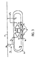
- a nacelle 11 is fixed under an airplane by means of a beam 10 from which a dynamic air intake takes place according to f1 then splits into f2 and f3.
- the air flow f3 is intended to supply a turbine of the axial or centripetal type 13 whose output shaft 15 drives a compressor 14 supplied with dynamic air according to the arrow f2.
- electronic equipment 16 emitting radiation or thermal radiation R intended to be cooled by the air coming from the turbine 13 according to arrow f6 and possibly by the air leaving the compressor C.
- the turbine 13 supplied with the dynamic air taken from outside the aircraft according to f1, f3 cools this air by adiabatic expansion and the air leaving the turbine according to f6 is used to cool the electrical equipment 16 heat sink, after which it is removed outside the nacelle according to f7.
- the centrifugal type compressor 14 coupled to the output shaft 15 of the turbine 13 is intended to recover the mechanical energy developed on said shaft 15 of said turbine 13 by the expansion of the gaseous air.
- the air according to f2 can on the one hand be evacuated towards the outside according to f4 and if its temperature is lower or equal to a set temperature equal to the maximum temperature capable of allowing said air to be used to cool the electronic equipment 16 possibly provided with a suitable connection device, it is then transferred by actuation of a solenoid valve not shown in the drawing according to f5 to said equipment 16 together with the air from of the turbine 13 according to f6, this air also being discharged outside according to f7 after heat transfer use. It is therefore clear that in the case where the temperature of the air coming from the compressor is low enough to be used in cooling the equipment 16, the flow of cooling air coming from the system will be the sum of the flow passing through the turbine and that passing through the compressor. As a result, the thermal conditioning of the equipment 16 will be improved to a certain extent,
- a forced flow is created in the nacelle between the outlet of the turbine according to f8 and the inlet of the compressor 14 according to f9, which makes it possible to increase the air speeds on the equipment 16 to be cooled and therefore to improve the heat exchanges between the latter and the cooling air which reaches it according to f8.
- Figures 2 and 3 are characterized with respect to the basic system illustrated in Figure 1 by comparable thermal performance, size and mass similar, even lower, and reduced acquisition cost.
Abstract
Description
La présente invention a pour objet une méthode pour le conditionnement thermique des équipements montés sur les aéronefs. Elle vise en outre des systèmes pour la mise en oeuvre de cette méthode.The present invention relates to a method for the thermal conditioning of equipment mounted on aircraft. It further relates to systems for implementing this method.
Sous certains aéronefs, notamment les avions militaires, sont fixés sous une structure inférieure de l'avion des nacelles renfermant des équipements électroniques. Par équipements électroniques, on entend ici tous les dispositifs, systèmes, appareils et autres renfermant au moins un composant électronique. Jusqu'à présent, on connaissait un certain nombre de dispositifs utilisés pour refroidir de l'air dynamique trop chaud au niveau de l'interface entre un aéronef et son environnement. Un de ces systèmes est constitué d'une machine thermique composée d'un compresseur en série avec un échangeur et une turbine de détente. Cet agencement est communément appelé "montage Bootstrap". Dans un tel agencement, la turbine de détente est alimentée par de l'air dont la pression est remontée par l'action d'un compresseur et dont la température est sensiblement égale à celle à la prise d'air grâce à l'action d'un échangeur. La détente à travers la turbine s'accompagne d'un refroidissement important de l'air. Si le système refroidisseur de l'échangeur est de l'air dynamique prélevé, il est clair que le système bootstrap est un agencement de refroidissement de l'air dynamique autonome, c'est-à-dire fonctionnant sur air dynamique exclusivement. Ce système présente l'inconvénient d'être volumineux, ce qui se traduit par un encombrement certain, et de présenter une masse relativement importante, ce qui n'est évidemment pas avantageux pour des aéronefs. En outre, sa réalisation présente une certaine complexité qui, conjointement avec une mise au point particulièrement difficile, se traduit par un prix de revient relativement élevé de l'ensemble.Under certain aircraft, notably military planes, nacelles containing electronic equipment are fixed under a lower structure of the aircraft. By electronic equipment is meant here all devices, systems, apparatus and the like containing at least one electronic component. Until now, a certain number of devices have been known which are used to cool dynamic air which is too hot at the interface between an aircraft and its environment. One of these systems consists of a thermal machine composed of a compressor in series with an exchanger and an expansion turbine. This arrangement is commonly called "Bootstrap mounting". In such an arrangement, the expansion turbine is supplied with air whose pressure is raised by the action of a compressor and whose temperature is substantially equal to that at the air intake thanks to the action of 'an exchanger. The expansion through the turbine is accompanied by significant cooling of the air. If the exchanger cooling system is taken from dynamic air, it is clear that the bootstrap system is an autonomous dynamic air cooling arrangement, that is to say operating on dynamic air exclusively. This system has the drawback of being bulky, which results in a certain bulk, and of having a relatively large mass, which is obviously not advantageous for aircraft. In addition, its production has a certain complexity which, together with a particularly difficult development, results in a relatively high cost price of the assembly.
Un objet de la présente invention est de proposer une méthode permettant d'obvier aux inconvénients mentionnés ci-dessus grâce à une possibilité de mise en oeuvre au moyen de systèmes nouveaux présentant un rapport encombrement/masse relativement réduit.An object of the present invention is to propose a method making it possible to overcome the mentioned drawbacks above thanks to a possibility of implementation by means of new systems having a relatively reduced overall dimensions / mass ratio.
Un autre objet de l'invention est de réaliser des systèmes permettant un conditionnement thermique efficace des équipements électroniques, tout en étant dune complexité moindre ce qui se traduit par un prix de revient nettement moins élevé.Another object of the invention is to provide systems for efficient thermal conditioning of electronic equipment, while being of less complexity which results in a significantly lower cost price.
La présente invention a donc pour objet une méthode pour le conditionnement thermique des équipements électroniques montés sur les aéronefs, cette méthode étant caractérisée en ce que Ion capte un courant ou flux d'air dynamique que l'on transfère à des premiers moyens permettant de conférer audit flux d'air un premier gradient négatif de température après quoi l'on transfère, lorsque ledit premier gradient négatif de température n'est pas suffisant pour atteindre une température nécessaire pour un refroidissement correct desdits équipements électroniques, le courant d'air issu desdits premiers moyens de refroidissement à des seconds moyens susceptibles de conférer un second gradient négatif de température audit flux d'air, après quoi on transfère le flux d'air issu directement des premiers moyens de refroidissement, le cas échéant combiné avec le flux d'air issu des seconds moyens de refroidissement au voisinage immédiat des équipements électroniques à refroidir, en réalisant ainsi un conditionnement thermique approprié desdits équipements électroniques.The present invention therefore relates to a method for the thermal conditioning of electronic equipment mounted on aircraft, this method being characterized in that Ion captures a dynamic current or flow of air which is transferred to the first means making it possible to impart to said air flow a first negative temperature gradient after which we transfer, when said first negative temperature gradient is not sufficient to reach a temperature necessary for correct cooling of said electronic equipment, the air flow coming from said first cooling means to second means capable of imparting a second negative temperature gradient to said air flow, after which the air flow coming directly from the first cooling means is transferred, if necessary combined with the air flow from second cooling means in the immediate vicinity of electronic equipment to cool, thereby achieving appropriate thermal conditioning of said electronic equipment.
Dans un premier système de conditionnement thermique mettant en oeuvre la méthode de conditionnement thermique des équipements électroniques montés sur les aéronefs selon l'invention, ce système comporte :
- une prise d'air dynamique ménagée sur la nacelle renfermant les équipements électroniques et scindée en deux dérivations ;
- des premiers moyens de refroidissement constitués par une turbine de détente, alimentée par une dérivation de la prise d'air d'ynamique ;
- des seconds moyens de refroidissement constitués par un système de coup les thermo-électriques, agencés pour que toutes les soudures froides forment un élément rapporté sur ou étant solidarisé à la conduite de sortie de turbine transférant l'air déjà refroidi vers les équipements électroniques, les soudures chaudes du système de couple électronique étant agencées à l'intérieur de la seconde dérivation issue de la prise d'air dynamique.
- a dynamic air intake provided on the nacelle containing the electronic equipment and split into two branches;
- first cooling means constituted by an expansion turbine, supplied by a bypass of the dynamic air intake;
- second cooling means constituted by a thermoelectric blow system, arranged so that all the cold welds form an insert on or being secured to the turbine outlet pipe transferring the already cooled air to the electronic equipment, the hot welds of the electronic torque system being arranged inside the second branch coming from the dynamic air intake.
Dans cette première forme de réalisation, la turbine est avantageusement accouplée à un générateur de courant continu alimentant le système à couples thermo-électrique. Bien que cette solution soit la plus avantageuse étant donné que l'énergie est fournie par la turbine de détente, il est évident que d'autres systèmes ou sources autonomes d'alimentation en courant continu peuvent alimenter en tout ou en partie le système à couple thermo-électrique.In this first embodiment, the turbine is advantageously coupled to a direct current generator supplying the thermoelectric couple system. Although this solution is the most advantageous since the energy is supplied by the expansion turbine, it is obvious that other autonomous systems or sources of direct current supply can supply all or part of the torque system thermoelectric.
Dans une seconde forme de réalisation selon l'invention, le système de conditionnement thermique des équipements électroniques comporte :
- une prise d'air dynamique ménagée sur la nacelle et scindée en deux dérivations ;
- des premiers moyens de refroidissement du flux d'air dynamique constitués par une turbine de type axial ou centripète alimentée par une première dérivation de la prise d'air dynamique ;
- des seconds moyens de refroidissement constitués par un compresseur de type centrifuge couplé à l'arbre de la turbine et alimenté par la seconde dérivation de la prise d'air dynamique ;
- des moyens permettant de transférer l'air refroidi issu de la turbine au voisinage immédiat des équipements électroniques ;
- des moyens permettant de transférer l'air issu du compresseur soit vers l'extérieur si cet air est à une température supérieure à la température maximale de l'air prévue pour le refroidissement des équipements électroniques, soit au voisinage immédiat des équipements électroniques à refroidir si la température est inférieure à la température maximale déterminée pour le refroidissement desdits équipements.
- a dynamic air intake provided on the nacelle and split into two branches;
- first means for cooling the dynamic air flow constituted by an axial or centripetal type turbine supplied by a first bypass of the dynamic air intake;
- second cooling means constituted by a centrifugal type compressor coupled to the turbine shaft and supplied by the second bypass of the dynamic air intake;
- means for transferring the cooled air from the turbine in the immediate vicinity of the electronic equipment;
- means for transferring the air from the compressor either to the outside if this air is at a temperature higher than the maximum air temperature provided for cooling the equipment electronics, or in the immediate vicinity of the electronic equipment to be cooled if the temperature is lower than the maximum temperature determined for cooling said equipment.
Les moyens sélectifs de transfert de l'air sortant du compresseur peuvent être constitués d'une thermo-vanne à trois voies, dûment programmée pour s'ouvrir ou se fermer en fonction d'une température de consigne égale à la température maximale.The selective means for transferring the air leaving the compressor may consist of a three-way thermovalve, duly programmed to open or close according to a set temperature equal to the maximum temperature.
Dans une variante de cette seconde forme de réalisation selon l'invention, le système de conditionnement thermique et la prise d'air dynamique alimentent uniquement la turbine tandis que le compresseur est alimenté par une prise d'air à l'intérieur de la nacelle.In a variant of this second embodiment according to the invention, the thermal conditioning system and the dynamic air intake supply only the turbine while the compressor is supplied by an air intake inside the nacelle.
D'autres caractéristiques et avantages de l'invention apparaîtront à la lecture de la description non limitative suivante de formes et de modes de réalisation selon l'invention, en référence aux dessins annexés dans lesquels :
- Figure 1 est une vue schématique d'une première forme de réalisation permettant la mise en oeuvre de l'invention ;
- Figure 2 est une vue schématique d'une seconde forme de réalisation permettant la mise en oeuvre de la méthode de l'invention ;
- Figure 3 est une vue schématique d'une variante de la forme de réalisation de la Figure 2.
- Figure 1 is a schematic view of a first embodiment for implementing the invention;
- Figure 2 is a schematic view of a second embodiment allowing the implementation of the method of the invention;
- Figure 3 is a schematic view of a variant of the embodiment of Figure 2.
Sur la Figure 1 est représenté un système de conditionnement thermique par refroidissement de l'air dynamique qui est capté par une prise d'air 1 puis immédiatement scindé en une dérivation la selon la flèche F1 et une dérivation 1b selon la flèche F2. Le courant d'air transféré par le conduit de dérivation 1a est envoyé à une turbine de détente 2 accouplée à un générateur de courant continu 3 qui alimente par des câbles conducteurs 4a, 4b un système de couples thermo-électriques 5, 6 dont les soudures froides sont rassemblées dans un élément 5 rapporté à la conduite 7 qui transfère l'air selon F3, F4 sur un équipement électronique 8 destiné à être refroidi. Une fois le refroidissement effectué, l'air est évacué selon F5 par la conduite 9 vers l'extérieur. L'air dynamique transféré par la dérivation 1b selon la flèche F2 est destiné à venir refroidir les soudures chaudes des couples thermo-électriques, incorporées dans un radiateur convecteur 6.In Figure 1 is shown a thermal conditioning system by cooling the dynamic air which is captured by an air intake 1 then immediately split into a branch la according to arrow F1 and a branch 1b according to arrow F2. The air current transferred by the
Le système fonctionne de la manière suivante :The system works as follows:
Si la température de l'air à la sortie de la turbine 2 est suffisamment basse, cet air peut être utilisé directement pour refroidir le matériel 8, par exemple par convection forcée. Dans ce cas, l'énergie électrique fournie par le générateur de courant continu 3, à partir de l'énergie mécanique récupérée sur l'arbre de la turbine 2, peut être utilisée pour toute application compatible de ce type d'alimentation électrique, les calories dégagées par le système étant évacuées dans le flux d'air extérieur.If the temperature of the air at the outlet of the turbine 2 is sufficiently low, this air can be used directly to cool the equipment 8, for example by forced convection. In this case, the electrical energy supplied by the direct current generator 3, from the mechanical energy recovered from the shaft of the turbine 2, can be used for any compatible application of this type of electrical supply, the calories released by the system being discharged into the outside air flow.
Dans le cas contraire, c'est-à-dire si le gradient négatif de température Δ T n'est pas suffisant pour atteindre une température To nécessaire pour un refroidissement correct de l'équipement électronique, il convient alors de mettre le système 5, 6 fonctionnant selon le principe de l'effet Pelletier sous tension continue à partir du générateur à courant continu, par exemple une magnéto 3 via les câbles électriques 4a, 4b. Cette mise sous tension peut être commandée par un interrupteur non représenté sur le dessin, actionné après amplification, par un signal généré par une thermo-sonde disposée sur le conduit 7. En effet, dans les systèmes à effet Pelletier, comme cela est bien connu, il se produit une différence de température entre les faces soudées opposées du couple. Lorsque le système 5, 6 est énergisé, l'élément 5 qui renferme les soudures froides confère par convection au courant dans la conduite 7 un gradient supplémentaire Δ T₂ qui vient s'ajouter au gradient négatif Δ T₁ en sortie de turbine et confère au flux d'air selon F4 un abaissement de température suffisant pour réaliser le conditionnement thermique approprié de l'équipement 8 éventuellement pourvu d'un dispositif de connexion approprié. Il est clair que l'élément 5 peut être agencé de façon que le nombre de couple à énergiser soit fonction de la température de refroidissement Tr à atteindre. On peut alors envisager un pilotage par thermo-sonde de façon à pouvoir régler de façon appropriée le nombre de couples thermo-électriques à énergiser. Il est clair que de tels pilotages et régulations peuvent être réalisés par des agencements de composants électroniques disponibles dans le commerce.Otherwise, that is to say if the negative temperature gradient Δ T is not sufficient to reach a temperature T o necessary for correct cooling of the electronic equipment, it is then necessary to set the
Dans la forme de réalisation de la Figure 2, une nacelle 11 est fixée sous un avion par l'intermédiaire d'une poutre 10 à partir de laquelle une prise d'air dynamique se fait selon f1 puis se scinde en f2 et en f3. Le flux d'air f3 est destiné à alimenter une turbine de type axial ou centripète 13 dont l'arbre de sortie 15 entraîne un compresseur 14 alimenté en air dynamique selon la flèche f2. Dans la nacelle 11 se trouve également un équipement électronique 16 émetteur de rayonnement ou de radiations thermiques R destiné à être refroidi par l'air issu de la turbine 13 selon la flèche f6 et éventuellement par l'air sortant du compresseur C.In the embodiment of FIG. 2, a nacelle 11 is fixed under an airplane by means of a
En fait, ce système de refroidissement fonctionne de la manière suivante :In fact, this cooling system works as follows:
La turbine 13, alimentée par l'air dynamique prélevé à l'extérieur de l'aéronef selon f1, f3 assure le refroidissement de cet air par détente adiabatique et l'air sortant de la turbine selon f6 sert à refroidir l'équipement électrique 16 dissipateur d'énergie calorifique, après quoi il est éliminé à l'extérieur de la nacelle selon f7. Le compresseur de type centrifuge 14 accouplé à l'arbre de sortie 15 de la turbine 13 est destiné à récupérer l'énergie mécanique développée sur ledit arbre 15 de ladite turbine 13 par la détente de l'air gazeux. Dans la forme de réalisation de la Figure 2, l'air selon f2 peut être d'une part évacué vers l'extérieur selon f4 et si sa température est inférieure ou égale à une température de consigne égale à la température maximale susceptible de permettre audit air d'être utilisé pour refroidir l'équipement électronique 16 éventuellement pourvu d'un dispositif de connexion approprié, il est alors transféré par actionnement d'une électro-vanne non représentée au dessin selon f5 vers ledit équipement 16 conjointement avec l'air issu de la turbine 13 selon f6, cet air étant également rejeté à l'extérieur selon f7 après utilisation caloporteuse. Il est donc clair que dans le cas où la température de l'air issu du compresseur est suffisamment basse pour être utilisée dans le refroidissement de l'équipement 16, le débit d'air de refroidissement issu du système sera la somme du débit passant dans la turbine et de celui transitant à travers le compresseur. Il en résulte que le conditionnement thermique de l'équipement 16 sera amélioré dans une certaine mesure,The
Dans la variante de réalisation de la Figure 3, on retrouve les mêmes éléments constitutifs que dans la forme de réalisation de la Figure 2, sauf que l'alimentation du compresseur 14 se fait selon f9 à partir d'un flux d'air prélevé directement dans la nacelle, par exemple, mais non exclusivement, à partir du flux d'air issu du système de convection incorporé à l'équipement électronique à refroidir 16. Un tel agencement présente trois avantages :In the alternative embodiment of Figure 3, there are the same components as in the embodiment of Figure 2, except that the supply of the
D'une part, l'action du compresseur 14 qui s'alimente dans la nacelle 11, met cette dernière en dépression ce qui contribue à augmenter le taux de détente disponible pour la turbine et par voie de conséquence, le refroidissement du gaz par détente dans cette dernière est accru.On the one hand, the action of the
Par ailleurs, il se crée un écoulement forcé dans la nacelle entre la sortie de la turbine selon f8 et l'entrée du compresseur 14 selon f9, ce qui permet d'augmenter les vitesses de l'air sur l'équipement 16 à refroidir et donc d'améliorer les échanges thermiques entre ce dernier et l'air de refroidissement qui lui arrive selon f8.In addition, a forced flow is created in the nacelle between the outlet of the turbine according to f8 and the inlet of the
En outre, le débit d'air prélevé à l'extérieur de l'avion est réduit, et étant donné que l'air passant par le compresseur 14 est prélevé dans la nacelle 11, il en résulte une réduction de la traînée de captation de la prise d'air dynamique, entrant dans le bilan global de traînée de l'avion.In addition, the air flow rate taken from outside the aircraft is reduced, and since the air passing through the
Dans tous les cas, il conviendra de réguler la perte de charge sur le circuit compresseur (f9, 14, f4) pour récupérer de façon effective l'intégralité de la puissance délivrée par la turbine 13.In all cases, it will be necessary to regulate the pressure drop on the compressor circuit (f9, 14, f4) to effectively recover all of the power delivered by the
Les formes de réalisation des Figures 2 et 3 se caractérisent par rapport au système de base illustré sur la Figure 1 par des performances thermiques comparables, un encombrement et une masse similaires, voire inférieurs, et un coût d'acquisition réduit.The embodiments of Figures 2 and 3 are characterized with respect to the basic system illustrated in Figure 1 by comparable thermal performance, size and mass similar, even lower, and reduced acquisition cost.
Il est clair que les systèmes décrits ci-dessus ne limitent en aucune façon la portée de l'invention qui englobe toutes les modifications et variantes issues du même principe de base, c'est-à-dire le conditionnement thermique d'équipement électronique monté sur aéronef au moyen de l'air dynamique prélevé à l'extérieur et traité par la coopération de deux sortes de moyens différents visant à conférer audit air dynamique un gradient négatif de température lui permettant d'être utilisé pour ledit conditionnement thermique. Par ailleurs, il est bien évident que les systèmes selon les Figures 1, 2 et 3 incorporent différents capteurs de pilotage permettant l'ouverture et la fermeture de vannes de commande de l'entrée et de la sortie des flux d'air au niveau de la turbine, du compresseur et de l'équipement à refroidir, respectivement.It is clear that the systems described above in no way limit the scope of the invention which encompasses all the modifications and variants resulting from the same basic principle, that is to say the thermal conditioning of mounted electronic equipment. on aircraft by means of dynamic air taken from the outside and treated by the cooperation of two different kinds of means aimed at giving said dynamic air a negative temperature gradient allowing it to be used for said thermal conditioning. Furthermore, it is quite obvious that the systems according to FIGS. 1, 2 and 3 incorporate different control sensors allowing the opening and closing of valves for controlling the entry and exit of air flows at the turbine, compressor and equipment to be cooled, respectively.
Claims (10)
Applications Claiming Priority (2)
| Application Number | Priority Date | Filing Date | Title |
|---|---|---|---|
| FR9005901A FR2661888B1 (en) | 1990-05-11 | 1990-05-11 | METHOD FOR THE THERMAL CONDITIONING OF ELECTRONIC EQUIPMENT MOUNTED ON AIRCRAFT AND SYSTEMS FOR ITS IMPLEMENTATION. |
| FR9005901 | 1990-05-11 |
Publications (2)
| Publication Number | Publication Date |
|---|---|
| EP0456549A1 true EP0456549A1 (en) | 1991-11-13 |
| EP0456549B1 EP0456549B1 (en) | 1996-01-03 |
Family
ID=9396518
Family Applications (1)
| Application Number | Title | Priority Date | Filing Date |
|---|---|---|---|
| EP91401115A Expired - Lifetime EP0456549B1 (en) | 1990-05-11 | 1991-04-26 | Method for thermally conditioning aircraft electronic equipment and systems thereof |
Country Status (5)
| Country | Link |
|---|---|
| US (1) | US5201182A (en) |
| EP (1) | EP0456549B1 (en) |
| JP (1) | JPH0524587A (en) |
| DE (1) | DE69115982T2 (en) |
| FR (1) | FR2661888B1 (en) |
Cited By (1)
| Publication number | Priority date | Publication date | Assignee | Title |
|---|---|---|---|---|
| EP0738655A2 (en) * | 1995-04-20 | 1996-10-23 | British Aerospace Public Limited Company | Environmental control system |
Families Citing this family (16)
| Publication number | Priority date | Publication date | Assignee | Title |
|---|---|---|---|---|
| JP2666902B2 (en) * | 1993-03-10 | 1997-10-22 | 松下電器産業株式会社 | Dehumidifier |
| DE29702259U1 (en) * | 1996-02-12 | 1997-06-19 | Cappelmann Wilfried H | Air conditioning unit for supplying conditioned air, for example to an aircraft located on the ground |
| ATE216910T1 (en) * | 1997-11-04 | 2002-05-15 | Pneumatik Berlin Gmbh | METHOD AND DEVICE FOR RECOVERING GASES |
| GB0029194D0 (en) * | 2000-11-30 | 2001-01-17 | Honeywell Normalair Garrett | Cooling apparatus |
| WO2003027575A2 (en) * | 2001-09-21 | 2003-04-03 | Collins & Aikman Automotive Company Inc. | Non-mechanical blower |
| US6908702B2 (en) * | 2002-05-03 | 2005-06-21 | Ion America Corporation | Fuel cell for airship power generation and heating |
| DE102006046114B4 (en) * | 2006-09-28 | 2012-02-02 | Airbus Operations Gmbh | Cooling arrangement for cooling a heat body for an aircraft |
| US20110219786A1 (en) * | 2010-03-11 | 2011-09-15 | Andres Michael J | Fluid heat sink powered vapor cycle system |
| US8967531B2 (en) | 2011-03-28 | 2015-03-03 | Rolls-Royce Corporation | Aircraft and airborne electrical power and thermal management system |
| WO2012135314A1 (en) | 2011-03-29 | 2012-10-04 | Rolls-Royce North American Technologies Inc. | Vehicle system |
| US9908635B2 (en) | 2013-03-15 | 2018-03-06 | Rolls-Royce North American Technologies Inc. | Aircraft system |
| DE102015122739B4 (en) * | 2015-12-23 | 2019-04-25 | Dr. Neumann Peltier-Technik Gmbh | Cooling device with Peltier element |
| CN205440884U (en) * | 2015-12-25 | 2016-08-10 | 广州亿航智能技术有限公司 | Multiaxis manned vehicle |
| CN205316736U (en) * | 2015-12-25 | 2016-06-15 | 广州亿航智能技术有限公司 | Multiaxis manned vehicle |
| US10455740B1 (en) | 2018-07-19 | 2019-10-22 | Ge Aviation Systems Llc | Electronic chassis with heat exchanger |
| RU2731043C2 (en) * | 2019-01-09 | 2020-08-28 | Российская Федерация, от имени которой выступает федеральное государственное казенное учреждение "Управление авиации Федеральной службы безопасности Российской Федерации" | Aviation suspended container with payload |
Citations (5)
| Publication number | Priority date | Publication date | Assignee | Title |
|---|---|---|---|---|
| US2477931A (en) * | 1947-01-06 | 1949-08-02 | Garrett Corp | Evaporative cooling system for aircraft having expansion means |
| US2503250A (en) * | 1948-06-02 | 1950-04-11 | Ernst R G Eckert | Air conditioning apparatus for high-speed aircraft |
| US2721456A (en) * | 1953-07-14 | 1955-10-25 | Fairchild Engine & Airplane | Aircraft air conditioning system |
| EP0342166A2 (en) * | 1988-05-13 | 1989-11-15 | Urbano Barbabella | Thermal conditioning device having at least one thermoelectric module with reverse thermoelectric effect |
| DE3824468A1 (en) * | 1988-07-19 | 1990-01-25 | Messerschmitt Boelkow Blohm | Method for providing mechanical power and cooling air in hypersonic aircraft |
Family Cites Families (7)
| Publication number | Priority date | Publication date | Assignee | Title |
|---|---|---|---|---|
| USRE24179E (en) * | 1956-07-10 | Electric generating and air cooling system | ||
| US2473496A (en) * | 1944-10-11 | 1949-06-14 | Garrett Corp | Air conditioning system |
| US2786341A (en) * | 1950-06-19 | 1957-03-26 | Garrett Corp | Direct evaporative vortex tube refrigeration system |
| US2839900A (en) * | 1950-08-31 | 1958-06-24 | Garrett Corp | Regenerative vortex cooling systems |
| US3236056A (en) * | 1965-01-11 | 1966-02-22 | Edward L Phillips | Apparatus for cooling automobiles and the like |
| US4209993A (en) * | 1978-03-06 | 1980-07-01 | United Technologies Corp. | Efficiency air cycle environmental control system |
| JPH0285010A (en) * | 1988-06-25 | 1990-03-26 | Nippon Denso Co Ltd | Cooling device |
-
1990
- 1990-05-11 FR FR9005901A patent/FR2661888B1/en not_active Expired - Fee Related
-
1991
- 1991-04-22 US US07/689,375 patent/US5201182A/en not_active Expired - Fee Related
- 1991-04-26 DE DE69115982T patent/DE69115982T2/en not_active Expired - Fee Related
- 1991-04-26 EP EP91401115A patent/EP0456549B1/en not_active Expired - Lifetime
- 1991-05-13 JP JP3135261A patent/JPH0524587A/en not_active Withdrawn
Patent Citations (5)
| Publication number | Priority date | Publication date | Assignee | Title |
|---|---|---|---|---|
| US2477931A (en) * | 1947-01-06 | 1949-08-02 | Garrett Corp | Evaporative cooling system for aircraft having expansion means |
| US2503250A (en) * | 1948-06-02 | 1950-04-11 | Ernst R G Eckert | Air conditioning apparatus for high-speed aircraft |
| US2721456A (en) * | 1953-07-14 | 1955-10-25 | Fairchild Engine & Airplane | Aircraft air conditioning system |
| EP0342166A2 (en) * | 1988-05-13 | 1989-11-15 | Urbano Barbabella | Thermal conditioning device having at least one thermoelectric module with reverse thermoelectric effect |
| DE3824468A1 (en) * | 1988-07-19 | 1990-01-25 | Messerschmitt Boelkow Blohm | Method for providing mechanical power and cooling air in hypersonic aircraft |
Non-Patent Citations (2)
| Title |
|---|
| ENGINEERING. (INCL. MACHINE SHOP MAGAZINE) vol. 222, no. 5, mai 1982, LONDON GB pages 348 - 349; R. AXE: "TAKING THE HEAT OUT OF AVIONICS", "System Layout";figure 1. * |
| PATENT ABSTRACTS OF JAPAN vol. 14, no. 277 (M-985)(4220) 15 juin 1990, & JP-A-02 85010 (NIPPON DENSO CO) 26 mars 1990, * |
Cited By (3)
| Publication number | Priority date | Publication date | Assignee | Title |
|---|---|---|---|---|
| EP0738655A2 (en) * | 1995-04-20 | 1996-10-23 | British Aerospace Public Limited Company | Environmental control system |
| EP0738655A3 (en) * | 1995-04-20 | 1998-01-21 | British Aerospace Public Limited Company | Environmental control system |
| US5860283A (en) * | 1995-04-20 | 1999-01-19 | British Aerospace Public Limited Company | Environmental control system |
Also Published As
| Publication number | Publication date |
|---|---|
| DE69115982D1 (en) | 1996-02-15 |
| EP0456549B1 (en) | 1996-01-03 |
| DE69115982T2 (en) | 1996-05-30 |
| US5201182A (en) | 1993-04-13 |
| FR2661888A1 (en) | 1991-11-15 |
| FR2661888B1 (en) | 1996-12-13 |
| JPH0524587A (en) | 1993-02-02 |
Similar Documents
| Publication | Publication Date | Title |
|---|---|---|
| EP0456549A1 (en) | Method for thermally conditioning aircraft electronic equipment and systems thereof | |
| EP1740892B1 (en) | Device and method for generating thermal units with magnetocaloric material | |
| CA2546685C (en) | Aircraft fluid cooling system and an aircraft provided with said system | |
| EP0780254B1 (en) | Vehicle supplementary heating employing the air conditioning fluid circuit | |
| CA2929951C (en) | Aircraft propulsion assembly with fire extinguishing system | |
| EP1953479A2 (en) | Device for cooling an electrical device in a turbomachine | |
| FR2557204A1 (en) | DEVICE FOR COOLING A TURBOMOTING COMPONENT | |
| CA2924411A1 (en) | Turbomachine designed to operate in turning gear mode | |
| FR2986905A1 (en) | Method for cooling electronic component in turbojet of aircraft, involves generating electric power from sensors by Seebeck effect, and causing cooling of electronic component by Peltier effect using electric power | |
| EP2112347A1 (en) | Engine cooling circuit | |
| FR3081514A1 (en) | PROPELLANT AIRCRAFT ASSEMBLY AND METHOD FOR REDUCING VENTILATION AIR FLOW IN THE AIRCRAFT PROPELLANT ASSEMBLY | |
| FR2982319A1 (en) | SYSTEM FOR CONTROLLING A TURBOMACHINE PNEUMATIC VALVE | |
| FR3096071A1 (en) | Clearance control between aircraft rotor blades and a housing | |
| EP0473494A1 (en) | Fuel supply system for a turbo-engine | |
| EP3414438B1 (en) | Charged air supply device of an internal combustion engine | |
| FR2968718A1 (en) | TURBOREACTOR COMPRISING A COOLING AIR COLLECTION SYSTEM WITH AUTOMATIC FLOW VARIATION VARIATION | |
| FR3081509A1 (en) | AIRCRAFT ENGINE WITH THERMAL CONTROL OF COMPRESSOR VEIN AND METHOD FOR THERMAL CONTROL THEREOF | |
| FR2698433A1 (en) | Air cycle air conditioning systems. | |
| FR2742605A1 (en) | Motor vehicle alternator cooled by air and liquid with air flow regulator | |
| WO2020109740A1 (en) | Air management system, in particular for an air conditioning and de-icing pack | |
| CA3137701A1 (en) | Turbomachine comprising a system for deicing the upstream cone, and associated method | |
| FR2469560A1 (en) | Exhaust gas regulation valve for supercharged engine - is opened on start=up for bringing oxygen probe for pollution circuit into operation | |
| FR2730761A1 (en) | Pressure regulator for steam in combined heat cycle circuit | |
| FR2761459A1 (en) | Gas cooker burner safety system | |
| FR3106854A1 (en) | Diesel engine thermal control system |
Legal Events
| Date | Code | Title | Description |
|---|---|---|---|
| PUAI | Public reference made under article 153(3) epc to a published international application that has entered the european phase |
Free format text: ORIGINAL CODE: 0009012 |
|
| AK | Designated contracting states |
Kind code of ref document: A1 Designated state(s): DE GB IT |
|
| 17P | Request for examination filed |
Effective date: 19911220 |
|
| 17Q | First examination report despatched |
Effective date: 19930521 |
|
| RAP1 | Party data changed (applicant data changed or rights of an application transferred) |
Owner name: THOMSON-CSF |
|
| GRAA | (expected) grant |
Free format text: ORIGINAL CODE: 0009210 |
|
| AK | Designated contracting states |
Kind code of ref document: B1 Designated state(s): DE GB IT |
|
| ITF | It: translation for a ep patent filed |
Owner name: JACOBACCI & PERANI S.P.A. |
|
| REF | Corresponds to: |
Ref document number: 69115982 Country of ref document: DE Date of ref document: 19960215 |
|
| GBT | Gb: translation of ep patent filed (gb section 77(6)(a)/1977) |
Effective date: 19960311 |
|
| PLBE | No opposition filed within time limit |
Free format text: ORIGINAL CODE: 0009261 |
|
| STAA | Information on the status of an ep patent application or granted ep patent |
Free format text: STATUS: NO OPPOSITION FILED WITHIN TIME LIMIT |
|
| 26N | No opposition filed | ||
| REG | Reference to a national code |
Ref country code: GB Ref legal event code: IF02 |
|
| PGFP | Annual fee paid to national office [announced via postgrant information from national office to epo] |
Ref country code: GB Payment date: 20050420 Year of fee payment: 15 |
|
| PGFP | Annual fee paid to national office [announced via postgrant information from national office to epo] |
Ref country code: DE Payment date: 20050421 Year of fee payment: 15 |
|
| PG25 | Lapsed in a contracting state [announced via postgrant information from national office to epo] |
Ref country code: GB Free format text: LAPSE BECAUSE OF NON-PAYMENT OF DUE FEES Effective date: 20060426 |
|
| PGFP | Annual fee paid to national office [announced via postgrant information from national office to epo] |
Ref country code: IT Payment date: 20060430 Year of fee payment: 16 |
|
| PG25 | Lapsed in a contracting state [announced via postgrant information from national office to epo] |
Ref country code: DE Free format text: LAPSE BECAUSE OF NON-PAYMENT OF DUE FEES Effective date: 20061101 |
|
| GBPC | Gb: european patent ceased through non-payment of renewal fee |
Effective date: 20060426 |
|
| PG25 | Lapsed in a contracting state [announced via postgrant information from national office to epo] |
Ref country code: IT Free format text: LAPSE BECAUSE OF NON-PAYMENT OF DUE FEES Effective date: 20070426 |