EP0455989B1 - Transport system between different levels of height for bobbins or bobbin tubes put in an upright position on independent supports - Google Patents
Transport system between different levels of height for bobbins or bobbin tubes put in an upright position on independent supports Download PDFInfo
- Publication number
- EP0455989B1 EP0455989B1 EP91105386A EP91105386A EP0455989B1 EP 0455989 B1 EP0455989 B1 EP 0455989B1 EP 91105386 A EP91105386 A EP 91105386A EP 91105386 A EP91105386 A EP 91105386A EP 0455989 B1 EP0455989 B1 EP 0455989B1
- Authority
- EP
- European Patent Office
- Prior art keywords
- transport
- individual supports
- individual
- transport system
- entrainment members
- Prior art date
- Legal status (The legal status is an assumption and is not a legal conclusion. Google has not performed a legal analysis and makes no representation as to the accuracy of the status listed.)
- Expired - Lifetime
Links
Images


Classifications
-
- B—PERFORMING OPERATIONS; TRANSPORTING
- B65—CONVEYING; PACKING; STORING; HANDLING THIN OR FILAMENTARY MATERIAL
- B65H—HANDLING THIN OR FILAMENTARY MATERIAL, e.g. SHEETS, WEBS, CABLES
- B65H67/00—Replacing or removing cores, receptacles, or completed packages at paying-out, winding, or depositing stations
- B65H67/06—Supplying cores, receptacles, or packages to, or transporting from, winding or depositing stations
-
- B—PERFORMING OPERATIONS; TRANSPORTING
- B65—CONVEYING; PACKING; STORING; HANDLING THIN OR FILAMENTARY MATERIAL
- B65H—HANDLING THIN OR FILAMENTARY MATERIAL, e.g. SHEETS, WEBS, CABLES
- B65H2701/00—Handled material; Storage means
- B65H2701/30—Handled filamentary material
- B65H2701/31—Textiles threads or artificial strands of filaments
Definitions
- the invention relates to a transport system according to the preamble of the first claim.
- JP-A-52-25 139 describes a transport system in which cops and sleeves are transported with their individual carriers in different transport planes. The respective horizontal transport takes place by means of frictional engagement through conveyor belts, the individual carriers being guided through guide slots along these transport routes.
- the transport levels are changed using elevators, which are formed by lifting and lowering transport track sections. Several individual carriers are combined in groups on these transport sections. These elevators work discontinuously and are not suitable for a high throughput of single girders.
- the generic DE-OS 36 30 670 also describes a transport system for coils and coil sleeves placed on independent individual carriers, in which parts of the transport path leading obliquely upwards are provided to bridge the height differences.
- This transport system can be used advantageously for the formation of an operating aisle between connected machines.
- the individual carriers In order to ensure that the individual carriers are also carried along by the conveyor belt in the transport sections which run obliquely upwards or downwards, they must at the same time rest against the plates forming the guide slot on the top of their base plate. It must be ensured that the frictional force between the conveyor belt and the individual carrier is significantly greater than the frictional force between the individual carrier and the guide plates. For this purpose, the conveyor belt must be pressed resiliently against the individual carrier so that it is also taken along.
- DE-OS 37 43 882 describes a similar system, but with the guide plates being replaced by flexible, round guides, which also have this guide slot for the base of the Form single carrier.
- the solution described in this publication allows the individual carriers to tilt during their transport.
- the transport belts, which also transport the individual carriers by friction, must be very narrow, since they are folded by 90 degrees at deflection points.
- such a pressing force of the transport belt against the individual carrier must be secured over the entire course of the route, with which friction can be achieved which clearly exceeds the sliding friction between the top of the individual carrier base and the guides forming the guide slot.
- the system is therefore also subject to relatively high wear.
- the object of the invention is to propose a simply constructed transport system which ensures high transport capacity, a small space requirement and constant functional reliability for single carriers with attached coils or bobbin sleeves between transport levels of different heights.
- the carriers attached to the rotating means of transport ensure that the individual carriers are securely grasped at the transfer point and are transported without any frictional forces. This minimizes wear on the individual carriers as well as the entire transport system. In this way, the functionality of the entire system is significantly extended.
- the avoidance of the frictional forces also prevents the different wear of the individual carriers and the transport route sections. As a result, a problem of known systems does not arise, which is that the different wear results in different frictional forces and thus leading to different entrainment of the individual carriers along the transport route. In known devices, this problem quickly increases to such an extent that it no longer functions.
- the drivers ensure that the individual carriers can be tilted into the new transport position without any significant space requirements. Due to the continuous operation of the system, a very high transport capacity is achieved. The simple structure ensures high functional reliability.
- a separation device of the pallets can be dispensed with at the delivery point of the individual carriers.
- this also increases the possible transport capacity.
- the invention also makes it possible to tilt horizontally delivered individual carriers at the delivery point by 90 degrees without the need for a bulky transport path curvature, as is known from the prior art.
- the individual carriers can be transferred from the carriers to another conveyor belt just as easily and continuously.
- Different variants for fixing the position of the individual carriers on the carriers do not cause any significant additional friction.
- Their structure is very simple.
- the transport system according to the invention also provides as a variant that the individual carriers remain on the carriers all the way through a cop bridge. It is also possible to do both To use trumes of the circulating means of transport for the transport of individual carriers, which means that capacity is doubled without taking up additional space.
- Transport routes are designed like a bridge, with an upper horizontal part being arranged at least at a height that allows free passage for people.
- a bridge of this type it is particularly problematic to lift the individual carriers with attached cops or sleeves from the level of the transport routes provided in the vicinity of the ground in the respective machine area to the level of the upper horizontal bridge part or to lower them again.
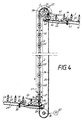
- cops 2 placed on individual carriers 1 are fed along a transport path 3 to a vertical transport path.
- the single carrier 1 have spokes 1 ', which connect a socket 1 ⁇ provided with the plug-in mandrel for the cop 2 with a casing ring 1 ′′′.
- the conveyor track 3 has a conveyor belt 4, which feeds the individual carriers 1 with cops 2 of the transfer point to the vertical transport route.
- the conveyor belt 4 is deflected by a pulley 4 '.
- the drive of this conveyor belt 4 is not shown here.
- the individual carriers are guided on their casing rings 1 ′′′ by guide rails 5 which have an angled part 5 'at the transfer point of the individual carriers. As a result, the individual carriers 1 are displaced transversely to the transport direction of the conveyor belt 4.
- the foremost individual carrier 1 abuts against a guide plate 10 or a stopper acting projection 10 'of this guide plate 10. In this position, it is gripped by a driving pin 13 fastened to a chain 12, which first lifts the front part of the single carrier and then into a of the openings between the spokes 1 'penetrates with further tilting of the single carrier.
- the single carrier tilts into a vertical position. In this vertical position, the individual carrier is then exclusively carried by the driver 13 held on which the jacket ring 1 ′′′ of the single carrier rests with its inside.
- an upper guide plate 6 is arranged such that it completely pushes the individual carrier 1 onto the driving pin 13 after it has tilted.
- the guide plate 6 then merges into a guide plate 11, by means of which the individual carriers are prevented from tipping during transport from the vertical position together with an opposite guide plate which is also provided with the reference number 11.
- the guide plates 11 cooperate with guide plates 10 on which the individual carriers slide with their underside and between which the driver pins 13 pass.
- the driver pins 13 contain notches 13 ', which are arranged so that they are in the transport direction of the driver 13 at the front.
- the notches 13 ' are attached at such a distance from the chain 12 that they capture the single carrier 1 ready for transfer on the inside of its casing ring 1 ′′′ and form a fulcrum during the tilting movement of the single carrier.
- the individual carrier 1 is then pushed further onto the driving pin 13. Through this notch 13 'it is ensured that the individual carrier can not slide down again when it is received by the driving pin 13.
- a guide plate 7 On the side opposite the guide plate 6, a guide plate 7 is attached, which has hinges 8, about which it can be pivoted. This guide plate 7 is pulled by a tension spring 9 against one of the guide plates 11. This resilient attachment of the guide plate 7 prevents individual carriers from jamming during the takeover.
- the circumferential chain which carries the driving pins 13 has a transport direction which laterally leads obliquely upwards from the stop position of the foremost single carrier to be taken over and then transitions into a vertical distance in order to achieve a transport direction component transverse to the tilting plane of the cop 2 on.
- the chain 12 has, in addition to sprockets 14 to 17, a sprocket 18 which conveys to the chain 12 the change in transport direction provided in this area. Due to this special design of the single carrier take-over, the tilting or tilted cop 2 is guided laterally away from the feed direction of the subsequent cop. As a result, a collision with the following cop can be avoided very effectively without having to provide a special stopping and separating device.
- the chain 12 is driven continuously by a motor 19 acting on the sprocket 17.
- the guide plates 10 and 11 have, for reasons of clarity in Fig. 1, broken off upper horizontal parts 10 'and 11', which are asymmetrical. This results from the fact that the individual carriers 1 are transported hanging on the driving pins 13, and in the horizontal part of the transport route the direction of transport is no longer counter to gravity.
- Lifting profiles 20 are arranged at the transfer point of the individual carriers from the driver pins 13 to an upper horizontal transport path 24, by means of which the individual carriers are tilted back into their horizontal position and lifted off the driver pins 13. For a safe take-over, it is necessary that the lifting profiles 20, which allow the free passage of the driving pins 13, guide the individual carriers until they have almost reached their horizontal position again.
- the conveyor track 24 has a conveyor belt 23, which is deflected by a deflecting roller 23 '.
- the drive of this conveyor belt 23 is not shown here.
- At least one guide rail 24 is also arranged along the transport path 22, which guides the individual carriers 1 to their casing ring 1 ′′′. This guide rail 24 is particularly important in the area of the transfer of the individual carriers 1 onto the conveyor belt 23.
- Fig. 3 shows a variant of the formation of a driver 26 on which a permanent magnet 27 is attached.
- the individual carriers 25 consist at least partially of ferromagnetic material. In this way it is possible to stabilize the position of the individual carriers 25 on the carriers 26.
- the individual carriers 25 have a recess 25 'in which the drivers 26 engage.
- These individual carriers 25 also have a jacket ring 25 ⁇ , which, however, is connected by a closed cover plate to the socket 25 trag carrying the plug-in mandrel for the cop 2.
- its surface facing the individual carrier has at least such an extent that there is contact with the casing ring 25 ⁇ in all of the transport directions provided.
- the conveyor track 28 has a conveyor belt 29 which is so entangled in its head region that the support surface formed by the upper run of the conveyor belt 29 is inclined by approximately 45 degrees for the individual carriers 25. This inclination is achieved by the guide roller 29 'of the conveyor belt 29.
- belt rollers 30 are arranged not far from the deflection roller 29 ', which fix the lower run of the conveyor belt 29 and together with a guide profile 31 which is arranged so far above the conveyor track 28 That the free passage of the individual supports 25 is possible, also fix the upper run so that the tilting of the tape in the head area does not propagate beyond this point.
- Guide profiles 32 and 33 ensure an exact positioning of the individual carrier 25 with cops 2.
- the guide profile 32 is arranged at a height at which it can lead the cops 2 to the winding-free head tip 2 '.
- This guide profile is shaped and arranged in such a way that it guides the cops 2 such that they largely retain their position perpendicular to this transport surface with the increasing inclination of the transport surface formed by the conveyor belt 29.
- the guide profile 33 ensures that the individual carriers cannot leave the conveyor belt 29 in the direction of its inclination.
- the guide profile 33 is angled at its rear end 33 in the transport direction so that it stops the individual carriers 25 in a position in which they are transferred to drive pins 35 of a chain 34.
- the chain 34 carrying the driving pins 35 at intervals is deflected by chain wheels 38 and 39.
- the sprocket 38 is continuously driven by a motor 40.
- this foremost single carrier 25 can be securely gripped and taken along by the driver pin.
- the guide profile 32 ensures a support of the head tip 2 'until the tilting of the individual carrier 25 is completed.
- Guide plates 36 and 37 arranged in pairs along the vertical transport path ensure that the individual carriers 25 remain securely on the driver pins 35 while maintaining the orientation of cops and individual carriers.
- sections 36 'and 37' of the guide surface are also asymmetrical, as has already been described in the first variant.
- lifting profiles 47 are assigned, with the aid of which the individual carriers are tilted until they assume a position in space which corresponds to the inclination of the conveyor belt 42 in its head region.
- the conveyor belt 42 is also at the upper delivery point at an angle of 45 degrees through the inclined arrangement of a deflecting roller 42 '.
- Band rollers 43 and a guide profile 44 also prevent this band entanglement from continuing to run.
- Guide profiles 45 and 46 are also provided at this point for the safe guiding of the individual supports 25 and the cops 2 at their head tips 2 '. The guide profile 45 stabilizes the tip of the head 2 'during the tilting when the cop 2 is being dispensed, as has already been described during the transfer.
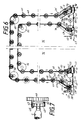
- a chain 48 carrying the carriers 49 runs over the entire area of a cop bridge.
- transfer and delivery points are arranged opposite each other in the area of the lower level, so that both trumes and thus transport directions of the chain 48 are used for the transport of individual carriers 65 with cops 2 or sleeves 66.
- the direction in which the individual carriers are fed or discharged is not rigidly predetermined. The arrangement of the transport system according to the invention is thus extremely flexible.
- the individual carriers 65 are transported along a transport path 58 on a transport belt 59 to the transfer point.
- the conveyor belt 59 is deflected by a pulley 59 '.
- the drive of the conveyor belt is not shown here.
- a guide plate 60 is designed in such a way that it stops the foremost individual carrier 65 with its edge arranged slightly above the upper run of the conveyor belt 59 and holds it ready for engagement by drivers 49 of the chain 48.
- the guide plate 60 and the opposite guide plate 61 then form upper guide surfaces for the individual carriers 65 during of the tipping process.
- the respective individual carrier 65 slides from the stop position through a groove 60 'of the guide plate 60 behind this guide plate.
- the two guide plates 60 and 61 are shaped so that the gap width tapers towards the chain 48 upwards.
- the chain is deflected by sprockets 51 to 56 and in the transfer areas of sprockets 51 ', 57 and 71 and in a delivery area of sprockets 54' and 71 '.
- the sprocket 54 is continuously driven by a motor 75.
- an operating aisle 76 is to be bridged between a spinning machine, to which the transport routes 58 and 63 belong, and a winding machine, to which the transport routes 67 and 73 belong.
- Copes 2 delivered by the spinning machine are transported over the cop bridge to the winding machine side and transferred to the transport path 73.
- Copes, sleeves 66, unwound from the winding machine become the drivers 49 of the chain 48 on the winding machine side fed. These sleeves 66 are transferred with their individual carriers 65 through the lower run of the chain 48 to the spinning machine side and thus to the transport path 63.
- lifting profiles 62 and 62a are arranged on the delivery side of the sleeves 66 to the spinning machine, which lift the individual carriers 65 with the sleeves 66 attached by 90 degrees and transfer them to the upper run of the conveyor belt 64.
- the lifting profile 62a has an oblique side edge through which the individual carriers 65 are additionally displaced laterally during their tilting movement.
- the base formed by the lifting profiles 62 and 62a for the base plates of the individual carriers are increasingly inclined downwards towards the transport path 63, which additionally supports the lateral offset. This measure is particularly necessary if the distance between the drivers 49 is chosen to be small to increase the transport capacity. Particularly when dispensing sleeves 66, a particularly large time offset is not necessary since the sleeves do not have a large diameter.
- the conveyor belt 64 transports out of the image plane. This avoids an additional change in transport direction and it is also possible to dispense with further guide elements along the belt 64.
- the conveyor belt 64 is deflected by a pulley 64 '.
- the drive of the conveyor belt is not shown here.
- the transfer and delivery of the individual carriers 65 on the winding machine side is carried out analogously.
- the transport path 67 forms a conveyor belt 68, which is deflected by a guide roller 68 '.
- guide plates 69 and 70 are provided, the guide plate 70 having a groove 70 '.
- Lifting profiles 72 and 72a are arranged on the delivery side of the cops 2 at the transport path 73.
- the transport path 73 is essentially formed by a conveyor belt 74, which by a Deflection roller 74 'is deflected.
- the drives of the conveyor belts 68 and 74 are also not shown in detail.
- the pallets 65 have a base 65 ', which carries the arbor for the cops 2 or sleeves 66.
- the base 65 ' is connected via spokes 65 ⁇ with a jacket ring 65 ′′′. In this example, only three spokes 65 ⁇ are arranged.
Landscapes
- Replacing, Conveying, And Pick-Finding For Filamentary Materials (AREA)
- Branching, Merging, And Special Transfer Between Conveyors (AREA)
Description
Die Erfindung betrifft ein Transportsystem nach dem Oberbegriff des ersten Anspruches.The invention relates to a transport system according to the preamble of the first claim.
Durch eine Vielzahl von Veröffentlichungen ist es bekannt, Spulen oder Spulenhülsen auf unabhängigen Einzelträgern in geschlossenen Transportsystemen zu transportieren. Die JP-A- 52-25 139 beschreibt ein Transportsystem, bei dem Kopse und Hülsen mit ihren Einzelträgern in verschiedenen Transportebenen transportiert werden. Dabei erfolgt der jeweilige Horizontaltransport mittels Reibschluß durch Transportbänder, wobei die Einzelträger durch Führungsschlitze entlang dieser Transportwege geführt werden. Der Wechsel der Transportebenen erfolgt mittels Elevatoren, die durch heb- und senkbare Transportbahnabschnitte gebildet werden. Auf diesen Transportabschnitten sind jeweils mehrere Einzelträger in Gruppen zusammengefaßt. Diese Elevatoren arbeiten diskontinuierlich und sind für einen hohen Durchsatz von Einzelträgern nicht geeignet.From a large number of publications it is known to transport coils or bobbin tubes on independent individual carriers in closed transport systems. JP-A-52-25 139 describes a transport system in which cops and sleeves are transported with their individual carriers in different transport planes. The respective horizontal transport takes place by means of frictional engagement through conveyor belts, the individual carriers being guided through guide slots along these transport routes. The transport levels are changed using elevators, which are formed by lifting and lowering transport track sections. Several individual carriers are combined in groups on these transport sections. These elevators work discontinuously and are not suitable for a high throughput of single girders.
Ein ähnliches, diskontinuierlich arbeitendes Transportsystem zum Heben und Senken von Einzelträgern mit senkrecht auf diese aufgesetzten Spulen oder Spulenhülsen ist in der DE-PS 36 09 071 beschrieben. Allerdings werden gemäß dieser Variante die Einzelträger nicht in Gruppen zusammengefaßt. Durch den diskontinuierlichen Betrieb ist aber auch bei dieser Lösung die Transportkapazität stark eingeschränkt.A similar, discontinuously operating transport system for lifting and lowering individual carriers with coils or coil sleeves placed vertically on them is described in DE-PS 36 09 071 described. However, according to this variant, the individual carriers are not grouped together. Due to the discontinuous operation, the transport capacity is also severely limited with this solution.
Die gattungsgemäße DE-OS 36 30 670 beschreibt ebenfalls ein Transportsystem für auf unabhängige Einzelträger aufgesetzte Spulen und Spulenhülsen, in dem zur Überbrückung der Höhenunterschiede schräg nach oben führende Teile der Transportstrecke vorgesehen sind. Dieses Transportsystem ist vorteilhaft für die Ausbildung eines Bedienungsganges zwischen verbundenen Maschinen einsetzbar. Um auch in den schräg nach oben oder unten verlaufenden Transportabschnitten die Mitnahme der Einzelträger durch das Transportband zu sichern, müssen diese gleichzeitig an den den Führungsschlitz bildenden Platten auf der Oberseite ihrer Grundplatte anliegen. Dabei muß gesichert sein, daß die Reibkraft zwischen Transportband und Einzelträger deutlich größer ist als die Reibkraft zwischen Einzelträger und Führungsplatten. Dazu muß das Transportband federnd so fest an den Einzelträger angedrückt werden, daß dieser auch mitgenommen wird. Abgesehen davon, daß die Anpreßkraft des Transportbandes über die gesamte Transportstrecke konstant gehalten werden muß, ist die Oberfläche der Grundplatten der Einzelträger jeweils über den gesamten Transportabschnitt den Reibkräften mit den Führungsplatten ausgesetzt. Dabei läßt sich eine verhältnismäßig schnelle Abnutzung der Einzelträger nicht vermeiden. Die Transportstrecken werden nur annähernd vertikal ausgerichtet, wodurch sich ein erhöhter Platzbedarf ergibt, der die Breite des Bedienungsganges einschränkt. Systembedingt ist außerdem nur eine allmähliche Transportrichtungsänderung möglich, die ebenfalls zu Lasten der Breite des Bedienungsganges geht.The generic DE-OS 36 30 670 also describes a transport system for coils and coil sleeves placed on independent individual carriers, in which parts of the transport path leading obliquely upwards are provided to bridge the height differences. This transport system can be used advantageously for the formation of an operating aisle between connected machines. In order to ensure that the individual carriers are also carried along by the conveyor belt in the transport sections which run obliquely upwards or downwards, they must at the same time rest against the plates forming the guide slot on the top of their base plate. It must be ensured that the frictional force between the conveyor belt and the individual carrier is significantly greater than the frictional force between the individual carrier and the guide plates. For this purpose, the conveyor belt must be pressed resiliently against the individual carrier so that it is also taken along. Apart from the fact that the pressing force of the conveyor belt must be kept constant over the entire transport route, the surface of the base plates of the individual carriers is exposed to the frictional forces with the guide plates over the entire transport section. A relatively rapid wear of the individual carriers cannot be avoided. The transport routes are only aligned approximately vertically, which results in an increased space requirement, which limits the width of the aisle. Due to the system, only a gradual change in transport direction is possible, which is also at the expense of the width of the aisle.
Die DE-OS 37 43 882 beschreibt ein ähnliches System, wobei jedoch die Führungsplatten durch biegsame, runde Führungen ersetzt sind, die ebenfalls diesen Führungsschlitz für den Sockel des Einzelträgers bilden. Die in dieser Veröffentlichung beschriebene Lösung gestattet ein Verkanten der Einzelträger während ihres Transportes. Die Transportriemen, die auch hier die Einzelträger durch Reibschluß transportieren, müssen dabei sehr schmal gestaltet sein, da sie an Umlenkstellen um 90 Grad verschränkt werden. Auch bei diesem System muß über den gesamten Streckenverlauf eine solche Anpreßkraft des Transportriemens gegen den Einzelträger gesichert werden, mit der eine Reibung erzielbar ist, die die Gleitreibung zwischen der Oberseite der Einzelträgerbasis und den den Führungsschlitz bildenden Führungen deutlich übertrifft. Das System unterliegt damit ebenfalls einem relativ hohen Verschleiß.DE-OS 37 43 882 describes a similar system, but with the guide plates being replaced by flexible, round guides, which also have this guide slot for the base of the Form single carrier. The solution described in this publication allows the individual carriers to tilt during their transport. The transport belts, which also transport the individual carriers by friction, must be very narrow, since they are folded by 90 degrees at deflection points. In this system too, such a pressing force of the transport belt against the individual carrier must be secured over the entire course of the route, with which friction can be achieved which clearly exceeds the sliding friction between the top of the individual carrier base and the guides forming the guide slot. The system is therefore also subject to relatively high wear.
Ausgehend von diesem Stand der Technik stellt sich die Erfindung die Aufgabe, ein einfach aufgebautes Transportsystem vorzuschlagen, welches für Einzelträger mit aufgesetzten Spulen oder Spulenhülsen zwischen in der Höhe unterschiedlichen Transportebenen eine hohe Transportkapazität, einen geringen Platzbedarf und eine gleichbleibende Funktionssicherheit gewährleistet.Based on this prior art, the object of the invention is to propose a simply constructed transport system which ensures high transport capacity, a small space requirement and constant functional reliability for single carriers with attached coils or bobbin sleeves between transport levels of different heights.
Diese Aufgabe wird erfindungsgemäß durch die Merkmale des Anspruches 1 gelöst.This object is achieved by the features of
Durch die an den umlaufenden Transportmitteln angebrachten Mitnehmer erfolgt ein sicheres Erfassen der Einzelträger an der Übergabestelle sowie ein Transport, der weitestgehend ohne Reibungskräfte auskommt. Dadurch wird der Verschleiß der Einzelträger sowie des gesamten Transportsystemes minimiert. Auf diese Weise wird auch die Funktionsfähigkeit des gesamten Systemes erheblich verlängert. Die Vermeidung der Reibungskräfte beugt auch dem unterschiedlichen Verschleiß der Einzelträger und der Transportstreckenabschnitte vor. Dadurch tritt ein Problem bekannter Systeme nicht auf, welches darin besteht, daß die unterschiedliche Abnutzung zu unterschiedlichen Reibkräften und damit einer unterschiedlichen Mitnahme der Einzelträger entlang der Transportstrecke führt. Dieses Problem weitet sich bei bekannten Vorrichtungen sehr schnell so stark aus, daß die Funktionsfähigkeit nicht mehr gegeben ist.The carriers attached to the rotating means of transport ensure that the individual carriers are securely grasped at the transfer point and are transported without any frictional forces. This minimizes wear on the individual carriers as well as the entire transport system. In this way, the functionality of the entire system is significantly extended. The avoidance of the frictional forces also prevents the different wear of the individual carriers and the transport route sections. As a result, a problem of known systems does not arise, which is that the different wear results in different frictional forces and thus leading to different entrainment of the individual carriers along the transport route. In known devices, this problem quickly increases to such an extent that it no longer functions.
Die Mitnehmer gewährleisten im Zusammenwirken mit an der Übergabestelle der Einzelträger angeordneten Leitflächen ein problemloses Kippen der Einzelträger in die neue Transportlage ohne nennenswerten Platzbedarf. Durch den kontinuierlichen Betrieb des Systems wird eine sehr hohe Transportkapazität erzielt. Der einfache Aufbau sichert eine hohe Funktionssicherheit.In cooperation with the guiding surfaces arranged at the transfer point of the individual carriers, the drivers ensure that the individual carriers can be tilted into the new transport position without any significant space requirements. Due to the continuous operation of the system, a very high transport capacity is achieved. The simple structure ensures high functional reliability.
Die Erfindung ist durch die Merkmale der Ansprüche 2 bis 20 vorteilhaft weitergebildet.The invention is advantageously further developed by the features of
Bei allen Varianten der Erfindung kann an der Abgabestelle der Einzelträger auf eine Vereinzelungsvorrichtung der Paletten verzichtet werden. Neben einer Vereinfachung der Konstruktion wird auch dadurch die mögliche Transportkapazität erhöht. Die Erfindung ermöglicht es auch, horizontal angelieferte Einzelträger an der Abgabestelle um 90 Grad zu kippen, ohne daß dazu eine raumgreifende Transportbahnkrümmung, wie sie aus dem Stand der Technik bekannt ist, notwendig ist.In all variants of the invention, a separation device of the pallets can be dispensed with at the delivery point of the individual carriers. In addition to simplifying the construction, this also increases the possible transport capacity. The invention also makes it possible to tilt horizontally delivered individual carriers at the delivery point by 90 degrees without the need for a bulky transport path curvature, as is known from the prior art.
Die Abgabe der Einzelträger von den Mitnehmern an ein weiteres Transportband erfolgt mit Hilfe von Abhebeprofilen ebenso problemlos und kontinuierlich. Verschiedene Varianten zur Fixierung der Lage der Einzelträger auf den Mitnehmern bewirken keine nennenswerte zusätzliche Reibung. Sie sind in ihrem Aufbau sehr einfach.With the help of lifting profiles, the individual carriers can be transferred from the carriers to another conveyor belt just as easily and continuously. Different variants for fixing the position of the individual carriers on the carriers do not cause any significant additional friction. Their structure is very simple.
Das erfindungsgemäße Transportsystem sieht als Variante auch vor, daß die Einzelträger auf ihrem gesamten Weg über eine Kopsbrücke auf den Mitnehmern verbleiben. Außerdem ist es möglich, beide Trumes der umlaufenden Transportmittel für den Transport von Einzelträgern zu nutzen, wodurch eine Kapazitätsverdoppelung ohne zusätzlichen Platzbedarf erreicht wird.The transport system according to the invention also provides as a variant that the individual carriers remain on the carriers all the way through a cop bridge. It is also possible to do both To use trumes of the circulating means of transport for the transport of individual carriers, which means that capacity is doubled without taking up additional space.
Die Erfindung soll nachstehend anhand von Ausführungsbeispielen näher erläutert werden. In den zugehörigen Zeichnungen zeigen:
- Fig. 1
- eine perspektivische Darstellung eines erfindungsgemäßen Transportsystemes zur Förderung von Einzelträgern von einer unteren in eine obere Ebene,
- Fig. 2
- eine Seitenansicht der Übergabestelle der Einzelträger nach Fig. 1,
- Fig. 3
- eine Variante der Ausbildung von Mitnehmer und Einzelträger,
- Fig. 4
- eine Variante der Erfindung mit abweichender Ausgestaltung der Übergabe- und der Abgabestelle der Einzelträger,
- Fig. 5
- eine Seitenansicht zu Fig. 4,
- Fig. 6
- eine Variante der Erfindung, bei der das umlaufende Transportband über eine gesamte Kopsbrücke unter Nutzung beider Transportrichtungen des Transportmittels verläuft, und
- Fig. 7
- eine Variante der Ausbildung eines Mitnehmers mit Auflageplatte.
- Fig. 1
- 1 shows a perspective illustration of a transport system according to the invention for conveying individual carriers from a lower to an upper level,
- Fig. 2
- 2 shows a side view of the transfer point of the individual carriers according to FIG. 1,
- Fig. 3
- a variant of the training of carriers and individual carriers,
- Fig. 4
- a variant of the invention with a different design of the transfer and delivery points of the individual carriers,
- Fig. 5
- 3 shows a side view of FIG. 4,
- Fig. 6
- a variant of the invention, in which the circulating conveyor belt runs over an entire Kopsbrücke using both transport directions of the transport means, and
- Fig. 7
- a variant of the formation of a driver with a platen.
Da insbesondere Maschinen zur Herstellung und Weiterverarbeitung von Kopsen eine erhebliche Länge aufweisen und Kopf an Kopf aufgestellt werden, ist es meist erwünscht, einen Bedienungsgang zwischen diesen Maschinen vorzusehen. Dazu sind in der Regel die Transportwege brückenartig gestaltet, wobei ein oberer horizontaler Teil mindestens in einer Höhe angeordnet ist, die den freien Durchgang für Personen gestattet. Bei einer dartigen Brücke ist es insbesondere problematisch, die Einzelträger mit aufgesetzten Kopsen beziehungsweise Hülsen vom in Bodennähe vorgesehenen Niveau der Transportwege im jeweiligen Maschinenbereich auf das Niveau des oberen horizontalen Brückenteiles zu heben beziehungsweise von diesem wieder abzusenken.Since in particular machines for the production and further processing of cops have a considerable length and are set up head to head, it is usually desirable to provide an operating aisle between these machines. These are usually the Transport routes are designed like a bridge, with an upper horizontal part being arranged at least at a height that allows free passage for people. In the case of a bridge of this type, it is particularly problematic to lift the individual carriers with attached cops or sleeves from the level of the transport routes provided in the vicinity of the ground in the respective machine area to the level of the upper horizontal bridge part or to lower them again.
Wie aus Fig. 1 zu erkennen ist, werden auf Einzelträger 1 aufgesetzte Kopse 2 entlang einer Transportbahn 3 einer Vertikaltransportstrecke zugeführt. Die Einzelträger 1 besitzen Speichen 1′, die einen mit dem Aufsteckdorn für den Kops 2 versehenen Sockel 1˝ mit einem Mantelring 1‴ verbinden.As can be seen from FIG. 1,
Die Transportbahn 3 weist ein Transportband 4 auf, welches die Einzelträger 1 mit Kopsen 2 der Übergabestelle an die Vertikaltransportstrecke zuführt. Das Transportband 4 wird durch eine Umlenkrolle 4′ umgelenkt. Der Antrieb dieses Transportbandes 4 ist hier nicht näher dargestellt. Die Einzelträger werden an ihren Mantelringen 1‴ durch Führungsschienen 5 geführt, die an der Übergabestelle der Einzelträger einen abgewinkelten Teil 5′ aufweisen. Dadurch werden die Einzelträger 1 quer zur Transportrichtung des Transportbandes 4 verschoben.The conveyor track 3 has a conveyor belt 4, which feeds the
Der jeweils vorderste Einzelträger 1 stößt gegen eine Führungsplatte 10 beziehungsweise einen als Stopper wirkenden Vorsprung 10′ dieser Führungsplatte 10. In dieser Position wird er von einem an einer Kette 12 befestigten Mitnehmerstift 13 erfaßt, der zunächst den vorderen Teil des Einzelträgers anhebt und dann in eine der Öffnungen zwischen den Speichen 1′ unter weiterem Kippen des Einzelträgers eindringt. Der Einzelträger kippt dabei in eine vertikale Lage. In dieser vertikalen Lage wird der Einzelträger dann ausschließlich vom Mitnehmer 13 gehalten, auf dem der Mantelring 1‴ des Einzelträgers mit seiner Innenseite aufliegt.The foremost
Wie aus Fig. 2 deutlich zu erkennen ist, ist ein oberes Leitblech 6 so angeordnet, daß es den Einzelträger 1 nach dessen Kippen vollständig auf den Mitnehmerstift 13 aufschiebt. Das Leitblech 6 geht dann in eine Führungsplatte 11 über, durch die ein Kippen der Einzelträger während des Transportes aus der Vertikallage gemeinsam mit einer gegenüberliegenden auch mit dem Bezugszeichen 11 versehenen Führungsplatte verhindert wird. Dabei wirken die Führungsplatten 11 mit Führungsplatten 10 zusammen, auf denen die Einzelträger mit ihrer Unterseite gleiten und zwischen denen die Mitnehmerstifte 13 hindurchtreten.As can be clearly seen from FIG. 2, an upper guide plate 6 is arranged such that it completely pushes the
Zur besseren Übernahme der Einzelträger 1 enthalten die Mitnehmerstifte 13 Kerben 13′, die so angeordnet sind, daß sie in Transportrichtung der Mitnehmer 13 vorn liegen. Die Kerben 13′ sind in einem solchen Abstand von der Kette 12 angebracht, daß sie den für die Übergabe bereitstehenden Einzelträger 1 an der Innenseite seines Mantelringes 1‴ erfassen und während der Kippbewegung des Einzelträgers einen Drehpunkt bilden. Je nach Anordnung weiterer Leitbleche wird dann der Einzelträger 1 weiter auf den Mitnehmerstift 13 geschoben. Durch diese Kerbe 13′ ist gesichert, daß der Einzelträger bei der Aufnahme durch den Mitnehmerstift 13 nicht wieder von diesem heruntergleiten kann.To better take over the
Auf der dem Leitblech 6 gegenüberliegenden Seite ist ein Leitblech 7 angebracht, welches Scharniere 8 besitzt, um die es schwenkbar ist. Dieses Leitblech 7 wird durch eine Zugfeder 9 gegen eine der Führungsplatten 11 gezogen. Durch diese federnde Anbringung des Leitbleches 7 wird ein Verklemmen von Einzelträgern bei der Übernahme verhindert.On the side opposite the guide plate 6, a guide plate 7 is attached, which has hinges 8, about which it can be pivoted. This guide plate 7 is pulled by a tension spring 9 against one of the
Wie des weiteren der Fig. 1 zu entnehmen ist, weist die die Mitnehmerstifte 13 tragende, umlaufende Kette eine von der Stopposition des vordersten zu übernehmenden Einzelträgers seitlich schräg nach oben führende, dann in eine Vertikalstrecke übergehende Transportrichtung zum Erzielen einer Transportrichtungskomponente quer zur Kippebene des Kopses 2 auf. Dazu weist die Kette 12 neben Kettenrädern 14 bis 17 noch ein Kettenrad 18 auf, welches der Kette 12 die in diesem Bereich vorgesehene Transportrichtungsänderung vermittelt. Durch diese spezielle Gestaltung der Einzelträgerübernahme wird der kippende beziehungsweise gekippte Kops 2 seitlich von der Zuführrichtung des Nachfolgekopses weggeführt. Dadurch kann sehr effektiv eine Kollision mit dem Nachfolgekops vermieden werden, ohne daß dazu eine besondere Stopp- und Vereinzelungsvorrichtung vorgesehen werden müßte.As can further be seen from FIG. 1, the circumferential chain which carries the driving pins 13 has a transport direction which laterally leads obliquely upwards from the stop position of the foremost single carrier to be taken over and then transitions into a vertical distance in order to achieve a transport direction component transverse to the tilting plane of the
Bei vorliegender Variante wird die Kette 12 kontinuierlich durch einen auf das Kettenrad 17 wirkenden Motor 19 angetrieben.In the present variant, the
Die Führungsplatten 10 und 11 weisen aus Gründen der Übersichtlichkeit in Fig. 1 abgebrochene obere Horizontalteile 10′ und 11′ auf, die asymmetrisch ausgebildet sind. Das resultiert daraus, daß die Einzelträger 1 an den Mitnehmerstiften 13 hängend transportiert werden, und im Horizontalteil der Transportstrecke die Transportrichtung nicht mehr der Schwerkraft entgegengerichtet ist.The
Am Übergabepunkt der Einzelträger von den Mitnehmerstiften 13 an eine obere horizontalliegende Transportbahn 24 sind Abhebeprofile 20 angeordnet, durch die die Einzelträger wieder in ihre Horizontallage gekippt und von den Mitnehmerstiften 13 abgehoben werden. Für eine sichere Übernahme ist es dabei notwendig, daß die Abhebeprofile 20, die den freien Durchgang der Mitnehmerstifte 13 gestatten, die Einzelträger so lange führen, bis sie annähernd ihre Horizontallage wieder erreicht haben.Lifting profiles 20 are arranged at the transfer point of the individual carriers from the driver pins 13 to an upper horizontal transport path 24, by means of which the individual carriers are tilted back into their horizontal position and lifted off the driver pins 13. For a safe take-over, it is necessary that the lifting profiles 20, which allow the free passage of the driving pins 13, guide the individual carriers until they have almost reached their horizontal position again.
Unterstützend wirkt dabei ein Führungsprofil 21, auf dem während des Kippens die Kopse 2 mit ihrer bewicklungsfreien Kopsspitze 2′ aufliegen. Dadurch ist ein nahezu ruckfreies Ändern der Lage der Kopse 2 und Ändern ihrer Transportrichtung gewährleistet.This is supported by a guide profile 21, on which the
Die Transportbahn 24 weist ein Transportband 23 auf, welches durch eine Umlenkrolle 23′ umgelenkt wird. Der Antrieb dieses Transportbandes 23 ist hier nicht näher dargestellt. Entlang der Transportbahn 22 ist noch mindestens eine Führungsschiene 24 angeordnet, die die Einzelträger 1 an ihren Mantelring 1‴ führt. Besonders wichtig ist diese Führungsschiene 24 im Bereich der Übernahme der Einzelträger 1 auf das Transportband 23.The conveyor track 24 has a
Fig. 3 zeigt eine Variante der Ausbildung eines Mitnehmers 26, auf dem ein Permanentmagnet 27 angebracht ist. Die Einzelträger 25 bestehen in diesem Fall zumindest teilweise aus ferromagnetischem Material. Auf diese Weise ist es möglich, die Lage der Einzelträger 25 auf den Mitnehmern 26 zu stabilisieren. Die Einzelträger 25 weisen bei dieser Variante eine Ausnehmung 25′ auf, in die die Mitnehmer 26 eingreifen. Auch diese Einzelträger 25 besitzen einen Mantelring 25˝, der allerdings durch eine geschlossene Deckplatte mit dem den Aufsteckdorn für den Kops 2 tragenden Sockel 25‴ verbunden ist. Bei der Ausbildung des Magneten 27 ist zu beachten, daß dessen dem Einzelträger zugewandte Oberfläche mindestens ein solches Ausmaß hat, daß ein Kontakt zum Mantelring 25˝ bei allen vorgesehenen Transportrichtungen vorhanden ist.Fig. 3 shows a variant of the formation of a
Zur Gewährleistung einer ruckfreien Übernahme und Übergabe der Einzelträger 1 ist es von Vorteil, wenn deren äußere Unterkante etwas abgeschrägt ist.To ensure smooth takeover and transfer of the
In den Fig. 4 und 5 ist eine Variante der Erfindung dargestellt, bei der die Übergabe und Abgabe der Einzelträger abweichend gestaltet ist. Eine in einer unteren Ebene angeordnete Transportbahn 28 weist ein Transportband 29 auf, welches in seinem Kopfbereich so verschränkt ist, daß die durch das obere Trum des Transportbandes 29 gebildete Auflagefläche für die Einzelträger 25 um zirka 45 Grad geneigt ist. Diese Neigung wird durch die Umlenkrolle 29′ des Transportbandes 29 erzielt. Um das Verschränken des Transportbandes 29 auf einen Endabschnitt dieses Bandes beschränken zu können, sind Bandrollen 30 unweit von der Umlenkrolle 29′ angeordnet, die das untere Trum des Transportbandes 29 fixieren und gemeinsam mit einem Führungsprofil 31, welches so weit über der Transportbahn 28 angeordnet ist, daß der freie Durchtritt der Einzelträger 25 möglich ist, auch das obere Trum so festlegen, daß sich das Verkanten des Bandes im Kopfbereich nicht über diesen Punkt fortpflanzt. Führungsprofile 32 und 33 gewährleisten ein exaktes Positionieren der Einzelträger 25 mit Kopsen 2. Dabei ist das Führungsprofil 32 in einer Höhe angeordnet, in der es die Kopse 2 an der bewicklungsfreien Kopsspitze 2′ führen kann. Dieses Führungsprofil ist so geformt und angeordnet, daß es die Kopse 2 so führt, daß diese bei der zunehmenden Neigung der durch das Transportband 29 gebildeten Transportfläche ihre gegenüber dieser Transportfläche senkrechte Lage weitestgehend beibehalten. Das Führungsprofil 33 sorgt dafür, daß die Einzelträger das Transportband 29 in dessen Neigungsrichtung nicht verlassen können. Außerdem ist das Führungsprofil 33 an seinem in Transportrichtung gelegenen hinteren Ende 33′ so abgewinkelt, daß es die Einzelträger 25 in einer Position stoppt, in der diese an Mitnehmerstifte 35 einer Kette 34 übergeben werden.4 and 5, a variant of the invention is shown, in which the transfer and delivery of the individual carriers is designed differently. One arranged in a lower level The
Die die Mitnehmerstifte 35 in Abständen tragende Kette 34 wird durch Kettenräder 38 und 39 umgelenkt. Das Kettenrad 38 wird von einem Motor 40 kontinuierlich angetrieben.The
Wie insbesondere aus Fig. 5 zu erkennen ist, überragt der in der Abgabeposition durch die Mitnehmerstifte 35 am hinteren Ende 33′ des Führungsprofiles 33 gestoppte Einzelträger das Transportband 29 in Richtung auf die Kette 34. Auf diese Weise wird einerseits der freie Vorbeigang der Mitnehmerstifte 35 am Transportband 29 beziehungsweise der Umlenkrolle 29′ gewährleistet. Andererseits kann dieser vorderste Einzelträger 25 sicher vom Mitnehmerstift erfaßt und mitgenommen werden. Dabei gewährleistet das Führungsprofil 32 eine Auflage der Kopsspitze 2′ so lange, bis der Kippvorgang des Einzelträgers 25 abgeschlossen ist. Paarweise entlang der vertikalen Transportstrecke angeordnete Führungsbleche 36 und 37 gewährleisten den sicheren Verbleib der Einzelträger 25 auf den Mitnehmerstiften 35 unter Beibehaltung der Orientierung von Kopsen und Einzelträgern. Im Bereich des oberen Kettenrades 39 sind Abschnitte 36′ und 37′ der Führungsfläche ebenso asymmetrisch ausgebildet, wie das bereits in der ersten Variante beschrieben wurde.As can be seen in particular from Fig. 5, the single carrier stopped in the delivery position by the driving pins 35 at the rear end 33 'of the
An der Übergabestelle der Einzelträger mit Kopsen auf eine in einer oberen Ebene angeordnete Transportbahn 41 sind Abhebeprofile 47 zugeordnet, mit deren Hilfe die Einzelträger so weit gekippt werden, bis sie eine Lage im Raum einnehmen, die der Neigung des Transportbandes 42 in seinem Kopfbereich entspricht. Analog der unteren Übergabestelle ist an der oberen Abgabestelle ebenfalls das Transportband 42 etwa in einem Winkel von 45 Grad durch die geneigte Anordnung einer Umlenkrolle 42′ verschränkt. Durch Bandrollen 43 und ein Führungsprofil 44 wird ebenso das Weiterlaufen dieser Bandverschränkung verhindert. Führungsprofile 45 und 46 sind auch an dieser Stelle für das sichere Führen der Einzelträger 25 sowie der Kopse 2 an ihren Kopsspitzen 2′ vorgesehen. Dabei stabilisiert das Führungsprofil 45 während des Kippens bei der Abgabe des Kopses 2 die Kopsspitze 2′ ebenso, wie das bei der Übergabe bereits beschrieben wurde.At the transfer point of the individual carriers with cops on a
Erst nachdem der Einzelträger 25 bei der Übergabe von einem Mitnehmerstift 35 erfaßt und zumindest um einen bestimmten Betrag in die Vertikalrichtung geschwenkt wurde, verliert der nachfolgende Einzelträger 25 Kontakt zu diesem vorderen Einzelträger. Erst dann kann der nachfolgende Einzelträger 25 weiter in Richtung auf die Übergabeposition transportiert werden. Dabei ist der Zeitraum, bis dieser nachfolgende Einzelträger direkt an der Übergabeposition ankommt, groß genug, um den vorangehenden Einzelträger so weit in Vertikalrichtung zu bewegen, daß der schrägliegende nachfolgende Einzelträger 25 mit dem vorangehenden Kops 2 nicht kollidieren kann. Dabei ist von Vorteil, daß die vertikale Ausdehnung der in der Übergabeposition ankommenden Kopse 2 durch deren Neigung entsprechend reduziert ist. Dadurch kann auch bei dieser Variante auf eine Stopp- und Vereinzelungsvorrichtung verzichtet werden.Only after the
Bei der in den Fig. 6 und 7 dargestellten Variante der Erfindung verläuft eine die Mitnehmer 49 tragende Kette 48 über den gesamten Bereich einer Kopsbrücke. Außerdem sind im Bereich der unteren Ebene jeweils gegenüberliegend Übergabe- und Abgabestellen angeordnet, so daß beide Trumes und damit Transportrichtungen der Kette 48 für den Transport von Einzelträgern 65 mit Kopsen 2 beziehungsweise Hülsen 66 genutzt werden. Gegenüber den ersten Varianten wird hier auch demonstriert, daß die Richtung der Zuführung beziehungsweise Abführung der Einzelträger nicht starr vorgegeben ist. Damit ist die Anordnung des erfindungsgemäßen Transportsystems äußerst flexibel.In the variant of the invention shown in FIGS. 6 and 7, a
Die Einzelträger 65 werden entlang eines Transportweges 58 auf einem Transportband 59 an die Übergabestelle herantransportiert. Das Transportband 59 wird durch ein Umlenkrolle 59′ umgelenkt. Der Antrieb des Transportbandes ist hier nicht dargestellt. Eine Führungsplatte 60 ist so ausgebildet, daß sie den jeweils vordersten Einzelträger 65 mit ihrer etwas oberhalb des oberen Trumes des Transportbandes 59 angeordneten Kante stoppt und für das Erfassen durch Mitnehmer 49 der Kette 48 bereithält. Die Führungsplatte 60 und die ihr gegenüberliegende Führungsplatte 61 bilden dann obere Führungsflächen für die Einzelträger 65 während des Kippvorganges. Dabei gleitet der jeweilige Einzelträger 65 von der Stopposition durch eine Auskehlung 60′ der Führungsplatte 60 hinter diese Führungsplatte. Die beiden Führungsplatten 60 und 61 sind dabei so geformt, daß sich die Spaltbreite zur Kette 48 nach oben hin verjüngt. Dadurch wird der vom Mitnehmer 49 erfaßte Einzelträger 65 vollständig auf diesen Mitnehmer 49 aufgeschoben. Mit den Mitnehmern 49 sind Auflageplatten 50 für die Einzelträger 65 verbunden. Die Mitnehmer 49 selbst tragen an ihrem der Kette 48 abgewandten Ende eine stempelartige Verdickung 49′. Diese stempelartige Verdickung 49′ verhindert ein Abgleiten des jeweiligen Einzelträgers 65 vom Mitnehmer 49 beziehungsweise sichert eine gute Auflage des Einzelträgers 65 auf der Auflageplatte 50 während des gesamten Transportes.The
Bei dieser Variante ist es notwendig, daß entweder die Auflageplatte 50 auf dem Mitnehmer 49 oder der Mitnehmer 49 an der Kette 48 drehbar gelagert ist. Diese Notwendigkeit ergibt sich daraus, daß bei wechselnden Transportrichtungen gewährleistet werden muß, daß der jeweilige Einzelträger 65 voll auf der Auflageplatte 50 aufliegt.In this variant, it is necessary that either the
Die Kette wird von Kettenrädern 51 bis 56 sowie in den Übergabebereichen von Kettenrädern 51′, 57 und 71 und in einem Abgabebereich von Kettenrädern 54′ und 71′ zusätzlich umgelenkt. Das Kettenrad 54 wird von einem Motor 75 kontinuierlich angetrieben.The chain is deflected by sprockets 51 to 56 and in the transfer areas of
Bei vorliegendem Beispiel soll ein Bedienungsgang 76 zwischen einer Spinnmaschine, zu der die Transportwege 58 und 63 gehören, und einer Spulmaschine, zu der Transportwege 67 und 73 gehören, überbrückt werden. Dabei werden von der Spinnmaschine angelieferte Kopse 2 über die Kopsbrücke auf die Spulmaschinenseite transportiert und an den Transportweg 73 übergeben. Von der Spulmaschine abgespulte Kopse, Hülsen 66, werden auf der Spulmaschinenseite den Mitnehmern 49 der Kette 48 zugeführt. Diese Hülsen 66 werden mit ihren Einzelträgern 65 durch das untere Trum der Kette 48 auf die Spinnmaschinenseite und damit an den Transportweg 63 übergeben.In the present example, an operating
Entsprechend den vorherigen Beispielen sind an der Abgabeseite der Hülsen 66 an die Spinnmaschine Abhebeprofile 62 und 62a angeordnet, die die Einzelträger 65 mit den aufgesetzten Hülsen 66 um 90 Grad kippen und an das obere Trum des Transportbandes 64 übergeben. Das Abhebeprofil 62a weist eine schräge Seitenkante auf, durch die die Einzelträger 65 während ihrer Kippbewegung zusätzlich seitlich versetzt werden. Dabei ist es noch vorteilhaft, wenn die durch die Abhebeprofile 62 und 62a gebildete Unterlage für die Grundplatten der Einzelträger nach unten zunehmend zur Transportbahn 63 hin geneigt sind, wodurch zusätzlich der seitliche Versatz unterstützt wird. Diese Maßnahme ist insbesondere dann erforderlich, wenn der Abstand zwischen den Mitnehmern 49 zur Erhöhung der Transportkapazität gering gewählt ist. Dabei ist insbesondere bei der Abgabe von Hülsen 66 kein besonders großer zeitlicher Versatz notwendig, da die Hülsen keinen großen Durchmesser aufweisen.According to the previous examples, lifting
Das Transportband 64 transportiert bei diesem Beispiel aus der Bildebene heraus. Dadurch wird ein zusätzlicher Transportrichtungswechsel vermieden und es kann auch auf weitere Führungsorgane entlang des Bandes 64 verzichtet werden. Das Transportband 64 wird durch eine Umlenkrolle 64′ umgelenkt. Der Antrieb des Transportbandes ist hier nicht dargestellt. Die Übergabe und Abgabe der Einzelträger 65 auf der Spulmaschinenseite erfolgt analog. Den Transportweg 67 bildet dabei ein Transportband 68, welches durch eine Umlenkrolle 68′ umgelenkt wird. Hier sind Führungsplatten 69 und 70 vorgesehen, wobei die Führungsplatte 70 eine Auskehlung 70′ aufweist. Auf der Abgabeseite der Kopse 2 an den Transportweg 73 sind Abhebeprofile 72 und 72a angeordnet. Der Transportweg 73 wird im wesentlichen durch ein Transportband 74 gebildet, welches durch eine Umlenkrolle 74′ umgelenkt wird. Die Antriebe der Transportbänder 68 und 74 sind ebenfalls nicht näher dargestellt.In this example, the
Da die Mitnehmer 49 auf der Kette 48 in relativ geringem Abstand zueinander befestigt sind, ist auch an der Abgabestelle der Einzelträger 65, die mit Kopsen 2 besetzt sind, ein seitlicher Versatz während des Kippens erforderlich. Da an dieser Abgabestelle Kopse 2, die einen größeren Durchmesser als die Hülsen 66 besitzen, gekippt werden, muß ein größerer seitlicher Versatz erfolgen. Das geschieht hier analog der Übergabeseite durch eine seitliche Bewegungskomponente der Kette 48, die durch zusätzliche Kettenräder 54˝ und 71′ vermittelt wird. Auch dabei ist es von Vorteil, wenn die Abhebeprofile 72 und 72a mit ihrer die Auflagefläche für die Einzelträger 65 bildenden Oberfläche nach unten eine zunehmende Neigung zum Transportweg 73 hin aufweisen. Gegebenenfalls kann das Abhebeprofil 72a noch eine zusätzliche senkrechte Kante 72a′ besitzen, die die Führung des Einzelträgers 65 weiter verbessert.Since the
Die Paletten 65 besitzen einen Sockel 65′, der den Aufsteckdorn für die Kopse 2 beziehungsweise Hülsen 66 trägt. Der Sockel 65′ ist über Speichen 65˝ mit einem Mantelring 65‴ verbunden. In diesem Beispiel sind lediglich drei Speichen 65˝ angeordnet.The
Bei der Ausbildung der Speichen der Einzelträger ist es erforderlich, diese von der Unterseite her anzuschrägen, damit der jeweilige Mitnehmer problemlos in die zwischen den Speichen gebildete Öffnung eintreten kann.When designing the spokes of the individual carriers, it is necessary to chamfer them from the underside so that the respective driver can easily enter the opening formed between the spokes.
Claims (20)
- Transport system for bobbins or bobbin tubes put in an upright position on independent individual supports between transport planes at different levels, with a conveyor belt supplying the individual supports in a transport plane, means for tilting the bobbins or bobbin tubes in an upright position on this conveyor belt into a horizontal position for the substantially vertical transportation of their individual supports to the other transport plane and circulating transport means engaging on the individual supports for substantially vertical transportation of the individual supports, characterized in that the circulating transport means 12; 34; 48 are equipped with entrainment members 13; 26; 35; 49 which are spaced apart and come into form-locking engagement with the individual supports 1; 25; 65, that the means for tilting are formed by the entrainment members and guide surfaces 6, 7, 10, 11; 29; 60, 61, 69, 70 for the individual supports and that the transfer point for the individual supports to the entrainment means is located on the upwardly directed side of the circulating transport means supporting the entrainment members and the discharge point of the individual supports from the entrainment members is located on the downwardly directed side of the circulating transport means.
- Transport system according to Claim 1, characterized in that the individual supports 1; 25, 65 have recesses 25′ accessible from the underside of their base plates, inside a jacket ring 1‴; 25˝; 65‴ of the base plate with a passage therethrough and that the entrainment members 13; 26; 35; 49 attached to the circulating transport means 12; 34; 48 are constructed so that they engage in the recesses of the individual supports and are able to support the latter on their jacket ring during transportation.
- Transport system according to Claim 2, characterized in that the recesses form through openings in the base plate of the individual supports 1; 65, which are interrupted by spoke-like connecting members 1′, 65˝.
- Transport system according to one of Claims 1 to 3, characterized in that at the transfer point of the individual supports 25 to the entrainment members 35, the conveyor belt 29 supplying the individual supports and at the same time forming a guide surface for the individual supports is inclined about an imaginary axis in a transport direction of the supply extending at right angles to the tilting plane of the bobbin 2 or bobbin tube 66.
- Transport system according to one of Claims 1 to 4, characterized in that located at the transport point of the individual supports to the entrainment members is a stationary stopper 10; 33′; 60, 70, which stops the foremost individual support in a position in which it crosses the path of movement of the entrainment members at least by the jacket ring of its base plate.
- Transport system according to Claim 4 or 5, characterized in that provided at the transfer point of the individual supports 1; 25; 65 to the entrainment members are guide contours 6, 7; 32, 33, 36, 37; 60, 61, 69, 70 for the reliable supply of the bobbins 2 respectively bobbin tube 66 and/or the individual supports.
- Transport system according to Claim 6, characterized in that the circulating transport means 12; 48 supporting the entrainment members, from the stop position of the foremost individual support to be received, have a transport direction leading laterally obliquely upwards, then passing into a vertical section, for achieving a transport direction component perpendicular to the tilting plane of the bobbin or bobbin tube.
- Transport system according to Claim 6 or 7, characterized in that the circulating transport means 48 supporting the entrainment members have a transport direction leading laterally obliquely downwards to the discharge position of the individual supports, for achieving a transport direction component perpendicular to the tilting plane of the bobbin or bobbin tube.
- Transport system according to one of Claims 5 to 8, characterized in that at least one of the guide contours 7 is arranged resiliently with a spring force acting in the direction of the through route of the individual supports.
- Transport system according to one of Claims 1 to 9, characterized in that disposed at the discharge point of the individual supports are lifting sections 20; 47; 62, 62a, 72, 72a, which project into the transport path of the entrainment members, without impeding their free passage, which remove the individual supports from the transport path of the entrainment members and which tilt the bobbins or bobbin tubes placed on the individual supports back in the direction of their vertical position.
- Transport system according to one of Claims 1 to 10, characterized in that the lifting sections 62, 62a, 72, 72a are inclined downwards with their surface serving as a support face for the individual support 65 increasingly towards the transport paths 63, 73, on which the individual supports 65 are discharged.
- Transport system according to one of Claims 10 or 11, characterized in that the lifting sections 62a, 72a have an additional guide edge for the lateral guidance of the individual support 65.
- Transport system according to one of Claims 1 to 12, characterized in that provided along the transport path of the entrainment members 13; 35 are guides 10; 36, between which the entrainment members project and which serve as a support for the bottom faces of the individual supports.
- Transport system according to one of Claims 1 to 13, characterized in that the individual supports 25 consist partly of ferromagnetic material and that the entrainment members 26 are connected to magnets 27, which stabilize the position of the individual supports during transportation of the individual supports by the entrainment members.
- Transport system according to one of Claims 1 to 13, characterized in that at their end opposite the circulating transport means 48, the entrainment members 49 comprise a plunger-like thickened portion 49′ and at a distance from this plunger-like thickened portion, which corresponds at least to the height of a jacket ring 65‴ , support a support plate 50 and that the support plate 50 is mounted to rotate on the entrainment member 49 and/or the entrainment members 49 in the transport means 48.
- Transport system according to one of Claims 10 to 15, characterized in that disposed along the transport path of the entrainment members 13; 35 are guides 11; 37, which engage over the base plates of the transported individual supports.
- Transport system according to one of Claims 1 to 16, characterized in that on the part of their periphery, by which they are in contact with the individual supports during the entire transportation of the individual supports, even including a change of direction, the entrainment members 49 are constructed so that they render the sliding-off of the individual supports from the respective entrainment member difficult.
- Transport system according to one of Claims 1 to 17, characterized in that for bridging a service passage 76, the circulating transport means 48 supporting the entrainment members are guided one after the other over a vertical section, a horizontal section and once more a vertical section.
- Transport system according to one of Claims 1 to 17, characterized in that for bridging a service passage, two vertical transport sections formed by the entrainment members are connected by a conveyor belt 23; 42 extending in an upper plane allowing the free passage.
- Transport system according to one of Claims 1 to 19, characterized in that respectively transfer and discharge stations of the individual support 65 are arranged adjacent to the guide rollers 51, 54 lying in a lower plane, of the circulating transport means 48 supporting the entrainment members.
Applications Claiming Priority (2)
| Application Number | Priority Date | Filing Date | Title |
|---|---|---|---|
| DE4015173A DE4015173A1 (en) | 1990-05-11 | 1990-05-11 | TRANSPORTSYSTEM FOR SPOOLS OR REEL SLEEVES BETWEEN INDEPENDENT SINGLE CARRIERS AND BETWEEN AT HIGH DIFFERENT LEVELS OF TRANSPORT |
| DE4015173 | 1990-05-11 |
Publications (3)
| Publication Number | Publication Date |
|---|---|
| EP0455989A2 EP0455989A2 (en) | 1991-11-13 |
| EP0455989A3 EP0455989A3 (en) | 1991-12-27 |
| EP0455989B1 true EP0455989B1 (en) | 1994-07-06 |
Family
ID=6406203
Family Applications (1)
| Application Number | Title | Priority Date | Filing Date |
|---|---|---|---|
| EP91105386A Expired - Lifetime EP0455989B1 (en) | 1990-05-11 | 1991-04-05 | Transport system between different levels of height for bobbins or bobbin tubes put in an upright position on independent supports |
Country Status (4)
| Country | Link |
|---|---|
| US (1) | US5088591A (en) |
| EP (1) | EP0455989B1 (en) |
| JP (1) | JPH04226275A (en) |
| DE (2) | DE4015173A1 (en) |
Families Citing this family (10)
| Publication number | Priority date | Publication date | Assignee | Title |
|---|---|---|---|---|
| JPH0497770U (en) * | 1991-01-18 | 1992-08-24 | ||
| DE4224086C2 (en) * | 1992-07-22 | 1999-10-21 | Schlafhorst & Co W | Bobbin supply unit for supplying a winding machine with cops of different batches of yarn |
| DE4236038A1 (en) * | 1992-10-24 | 1994-04-28 | Schlafhorst & Co W | Caddy for transporting a textile spool or textile spool sleeve to and / or in a textile machine |
| DE4336751C2 (en) * | 1993-10-28 | 2002-04-25 | Lfk Gmbh | Method for the automatic detection of fixed or moving objects in the natural environment of a real-time image sequence |
| DE19816232A1 (en) * | 1998-04-10 | 1999-10-14 | Schlafhorst & Co W | Transport system for spinning bobbins and bobbin tubes with a transport path spanning one passage |
| DE19931982A1 (en) * | 1999-07-09 | 2001-01-11 | Schlafhorst & Co W | Conveyor for transporting bobbins between textile machines includes mechanical aid to assist transfer between vertical and horizontal sections |
| US8818322B2 (en) * | 2006-06-09 | 2014-08-26 | Trapeze Networks, Inc. | Untethered access point mesh system and method |
| JP6472961B2 (en) * | 2014-08-13 | 2019-02-20 | 日本電子株式会社 | Sample rack transport unit and automatic analysis system |
| DE102019110294A1 (en) * | 2019-04-18 | 2020-10-22 | Saurer Spinning Solutions Gmbh & Co. Kg | Tube storage and transport device for a textile machine producing cheese |
| CN112027807B (en) * | 2020-08-17 | 2022-01-28 | 四川大学 | Automatic reversing lifting conveying device for yarn pipe |
Family Cites Families (15)
| Publication number | Priority date | Publication date | Assignee | Title |
|---|---|---|---|---|
| DE466153C (en) * | 1926-06-20 | 1928-09-29 | Walter Kuepper | Chain conveyor for horizontal and vertical conveyance |
| GB1170660A (en) * | 1967-07-01 | 1969-11-12 | Giddings & Lewis Fraser Ltd | Magazine for Supplying Bobbins to a Winding Machine |
| DE7301717U (en) * | 1973-01-18 | 1973-05-10 | Licentia Gmbh | Kop container |
| GB1536931A (en) * | 1975-01-28 | 1978-12-29 | Ntn Toyo Bearing Co Ltd | Pin type transfer apparatus for apertured workpieces |
| JPS5225139A (en) * | 1975-08-18 | 1977-02-24 | Kanebo Ltd | Method of conveying bobbins of textile machine |
| FR2458724A1 (en) * | 1979-06-13 | 1981-01-02 | Renault | Hydraulic torque converter bridging control device - automatically suppresses bridging prior to transmission ratio change by controlling piston being moved out of its seating (PT 12.12.80) |
| JPS61217480A (en) * | 1985-03-18 | 1986-09-27 | Murata Mach Ltd | Bobbin conveying system |
| JPS6260774A (en) * | 1985-09-09 | 1987-03-17 | Murata Mach Ltd | Bobbin conveyor |
| DE3629561A1 (en) * | 1986-08-30 | 1988-03-03 | Schlafhorst & Co W | DEVICE FOR KEEPING THE NUMBER OF BETWEEN A SPINDING MACHINE AND A WINDING MACHINE IN A CIRCUIT |
| JPS6382285A (en) * | 1986-09-20 | 1988-04-13 | Murata Mach Ltd | Transfer device for tray |
| JP2552260B2 (en) * | 1987-08-29 | 1996-11-06 | 豊和工業株式会社 | Transfer method of roving bobbin |
| US4842206A (en) * | 1987-12-21 | 1989-06-27 | Murata Kikai Kabushiki Kaisha | Automatic yarn end finding device for a spinning bobbin |
| US5074401A (en) * | 1988-06-16 | 1991-12-24 | Kabushiki Kaisha Toyoda Jidoshokki Seisakusho | Bobbin-carrying apparatus of a combined fine spinning machine and winder |
| JP2680042B2 (en) * | 1988-06-21 | 1997-11-19 | 株式会社豊田自動織機製作所 | Bobbin transport device in spinning machine |
| DE58909239D1 (en) * | 1988-09-24 | 1995-06-22 | Rieter Ag Maschf | Spinning machine. |
-
1990
- 1990-05-11 DE DE4015173A patent/DE4015173A1/en not_active Withdrawn
-
1991
- 1991-04-05 DE DE59102101T patent/DE59102101D1/en not_active Expired - Fee Related
- 1991-04-05 EP EP91105386A patent/EP0455989B1/en not_active Expired - Lifetime
- 1991-05-10 JP JP3105369A patent/JPH04226275A/en active Pending
- 1991-05-13 US US07/699,452 patent/US5088591A/en not_active Expired - Fee Related
Also Published As
| Publication number | Publication date |
|---|---|
| JPH04226275A (en) | 1992-08-14 |
| EP0455989A2 (en) | 1991-11-13 |
| DE4015173A1 (en) | 1991-11-14 |
| EP0455989A3 (en) | 1991-12-27 |
| DE59102101D1 (en) | 1994-08-11 |
| US5088591A (en) | 1992-02-18 |
Similar Documents
| Publication | Publication Date | Title |
|---|---|---|
| DE3909786A1 (en) | Apparatus for transporting cops and tubes between planes changing in the course of transport | |
| DE3334977C2 (en) | ||
| DE4011797A1 (en) | TRANSPORT SYSTEM FOR AN AUTOMATIC TEXTILE MACHINE FOR THE CONTROLLED GUIDE OF PALLETS ALONG SPECIFIED TRANSPORT PATHS | |
| DE2457858C2 (en) | Device for aligning capsules | |
| EP0455989B1 (en) | Transport system between different levels of height for bobbins or bobbin tubes put in an upright position on independent supports | |
| DE4314462C2 (en) | Device for the vertical positioning of can bodies | |
| DE3733510A1 (en) | DEVICE FOR TRANSPORTING TEXTILE REELS | |
| DE1556693B2 (en) | DEVICE FOR ALIGNING A NUMBER OF AMPOULES IN A REGULAR ORDER | |
| EP1622778B2 (en) | Device and method for inserting sheets into an envelope | |
| DD140132A5 (en) | DEVICE FOR FEEDING A PACK MACHINE WITH SUESSWAREN | |
| DE4036214A1 (en) | Double track conveyor for workpiece - has carriers between top edges of conveyor side plates, with middle piece and guide piece | |
| DE3630670A1 (en) | SPOOL FEEDING DEVICE FOR TRANSPORTING SPIDER COILS | |
| DE2349608C3 (en) | Device for aligning containers | |
| DE3433706C2 (en) | ||
| DE3604372A1 (en) | DEVICE FOR FEEDING YARN BODIES TO AN AUTOMATIC WINDING DEVICE | |
| DE2249043A1 (en) | DEVICE FOR ALIGNMENT AND FEEDING OF BOTTLES OR DGL | |
| DE2421049A1 (en) | DEVICE FOR ALIGNING LOOSELY REMOVED HEADS | |
| DE3407804C2 (en) | ||
| EP0380930B1 (en) | Suspended transport system | |
| DE4124061C2 (en) | Conveyor device with two upright flat belt conveyors | |
| DE3039104A1 (en) | CONVEYORS, ESPECIALLY FOR BOOKBINDING WORKSHOPS | |
| EP0423519B1 (en) | Transporting device for conveying spining cans and use of the transporting device | |
| DE19624503A1 (en) | Suspended conveyor unit | |
| DE4113092C2 (en) | Tenon carriage transfer device on a ring spinning machine | |
| CH685872A5 (en) | Transport system for the transport of solid and Leerhuelsen in spinning and winding machines |
Legal Events
| Date | Code | Title | Description |
|---|---|---|---|
| PUAI | Public reference made under article 153(3) epc to a published international application that has entered the european phase |
Free format text: ORIGINAL CODE: 0009012 |
|
| PUAL | Search report despatched |
Free format text: ORIGINAL CODE: 0009013 |
|
| AK | Designated contracting states |
Kind code of ref document: A2 Designated state(s): CH DE FR IT LI |
|
| AK | Designated contracting states |
Kind code of ref document: A3 Designated state(s): CH DE FR IT LI |
|
| 17P | Request for examination filed |
Effective date: 19920206 |
|
| 17Q | First examination report despatched |
Effective date: 19930924 |
|
| ITF | It: translation for a ep patent filed |
Owner name: DE DOMINICIS & MAYER S.R.L. |
|
| GRAA | (expected) grant |
Free format text: ORIGINAL CODE: 0009210 |
|
| AK | Designated contracting states |
Kind code of ref document: B1 Designated state(s): CH DE FR IT LI |
|
| REF | Corresponds to: |
Ref document number: 59102101 Country of ref document: DE Date of ref document: 19940811 |
|
| ET | Fr: translation filed | ||
| PLBE | No opposition filed within time limit |
Free format text: ORIGINAL CODE: 0009261 |
|
| STAA | Information on the status of an ep patent application or granted ep patent |
Free format text: STATUS: NO OPPOSITION FILED WITHIN TIME LIMIT |
|
| 26N | No opposition filed | ||
| PGFP | Annual fee paid to national office [announced via postgrant information from national office to epo] |
Ref country code: FR Payment date: 19990419 Year of fee payment: 9 |
|
| PGFP | Annual fee paid to national office [announced via postgrant information from national office to epo] |
Ref country code: DE Payment date: 19990507 Year of fee payment: 9 Ref country code: CH Payment date: 19990507 Year of fee payment: 9 |
|
| PG25 | Lapsed in a contracting state [announced via postgrant information from national office to epo] |
Ref country code: LI Free format text: LAPSE BECAUSE OF NON-PAYMENT OF DUE FEES Effective date: 20000430 Ref country code: DE Free format text: LAPSE BECAUSE OF NON-PAYMENT OF DUE FEES Effective date: 20000430 Ref country code: CH Free format text: LAPSE BECAUSE OF NON-PAYMENT OF DUE FEES Effective date: 20000430 |
|
| REG | Reference to a national code |
Ref country code: CH Ref legal event code: PL |
|
| PG25 | Lapsed in a contracting state [announced via postgrant information from national office to epo] |
Ref country code: FR Free format text: LAPSE BECAUSE OF NON-PAYMENT OF DUE FEES Effective date: 20001229 |
|
| REG | Reference to a national code |
Ref country code: FR Ref legal event code: ST |
|
| PG25 | Lapsed in a contracting state [announced via postgrant information from national office to epo] |
Ref country code: IT Free format text: LAPSE BECAUSE OF NON-PAYMENT OF DUE FEES;WARNING: LAPSES OF ITALIAN PATENTS WITH EFFECTIVE DATE BEFORE 2007 MAY HAVE OCCURRED AT ANY TIME BEFORE 2007. THE CORRECT EFFECTIVE DATE MAY BE DIFFERENT FROM THE ONE RECORDED. Effective date: 20050405 |