EP0455877A2 - Dispositif de réglage de charge - Google Patents
Dispositif de réglage de charge Download PDFInfo
- Publication number
- EP0455877A2 EP0455877A2 EP90124326A EP90124326A EP0455877A2 EP 0455877 A2 EP0455877 A2 EP 0455877A2 EP 90124326 A EP90124326 A EP 90124326A EP 90124326 A EP90124326 A EP 90124326A EP 0455877 A2 EP0455877 A2 EP 0455877A2
- Authority
- EP
- European Patent Office
- Prior art keywords
- throttle valve
- valve shaft
- adjusting device
- load adjusting
- rotor
- Prior art date
- Legal status (The legal status is an assumption and is not a legal conclusion. Google has not performed a legal analysis and makes no representation as to the accuracy of the status listed.)
- Granted
Links
Images


Classifications
-
- F—MECHANICAL ENGINEERING; LIGHTING; HEATING; WEAPONS; BLASTING
- F02—COMBUSTION ENGINES; HOT-GAS OR COMBUSTION-PRODUCT ENGINE PLANTS
- F02D—CONTROLLING COMBUSTION ENGINES
- F02D11/00—Arrangements for, or adaptations to, non-automatic engine control initiation means, e.g. operator initiated
- F02D11/06—Arrangements for, or adaptations to, non-automatic engine control initiation means, e.g. operator initiated characterised by non-mechanical control linkages, e.g. fluid control linkages or by control linkages with power drive or assistance
- F02D11/10—Arrangements for, or adaptations to, non-automatic engine control initiation means, e.g. operator initiated characterised by non-mechanical control linkages, e.g. fluid control linkages or by control linkages with power drive or assistance of the electric type
Definitions
- the invention relates to a load adjustment device with a throttle valve which determines the performance of an internal combustion engine and which is connected in a rotationally fixed manner to a throttle valve shaft mounted in the throttle valve housing, the throttle valve shaft having an accelerator pedal-side mechanical linkage side and an actuating linkage side which has a coupling element for mechanically decoupling the throttle valve is assigned with a pinion, which is drivingly connected to the throttle valve shaft via further gear elements.
- the servomotor is equipped on the output side at the end of its shaft with a pinion which engages with an intermediate wheel which in turn interacts with a drive wheel arranged on a bearing shaft and correspondingly adjusts the throttle valve arranged in the throttle valve housing to the desired position. Since the installation space between the bearing shaft of the servomotor and the throttle valve shaft is very small, the size of the individual gearwheels is also fixed and thus also the overall transmission ratio of the gearbox for adjusting the throttle valve. Since the transmission ratio of the transmission cannot be chosen arbitrarily large, the servomotor must be designed much stronger so that the individual frictional resistances of the transmission parts and the actuating forces counteracting when the throttle valve is pivoted can be overcome.
- the invention has for its object to design and arrange the individual actuators for pivoting the throttle valve in such a way that a gear with a large transmission ratio can be provided to overcome the torque occurring at the throttle valve.
- the object is achieved according to the invention in that the pinion is drivingly connected to the throttle valve shaft via at least one articulated gear having a gear segment.
- the use of an articulated gearbox allows the individual gear parts to be arranged in the smallest space so that a very large transmission ratio can be achieved. This is advantageously achieved in that a gear segment is used instead of a gear wheel which is very large in diameter.
- the articulated gear is designed as a three- or four-articulated gear and on the drive side has the pinion which is in engagement with the gearwheel segment designed as the first link. Since the gear segment is also designed as a handlebar, a multi-link transmission can be obtained in a simple manner, with which very large actuating forces can be overcome in the smallest space. Thus, a low-power and therefore inexpensive electric motor can be used, which contributes to a cost reduction of the entire load adjustment device.
- the first link is pivotally mounted on the throttle valve body and a second link is articulated between its articulation point on the throttle valve body and its gear segment and is articulated to a rotor at its end opposite the articulation point which is drivingly connected to the throttle valve shaft.
- a large transmission ratio can be achieved in that the second link provided between the rotor and the gear segment is connected in an articulated manner with its one end in the region of the articulation of the first link to the throttle valve housing and with its other end to the outer end of the rotor.
- the use of a multi-link transmission is particularly advantageous when the center distance between the drive pinion and the throttle valve shaft is very small and can no longer be changed.
- the rotor in a further embodiment of the invention, it is advantageous for the rotor to have a driver element which is connected to the throttle valve shaft in a rotationally fixed manner via a control element part which permits free-wheeling. This ensures in a simple manner that when the servomotor is activated, the throttle valve for idle operation is adjusted according to a manipulated variable.
- the end of the throttle valve shaft is designed as a drive element with a stop against which the driver element can be brought into contact when the servomotor, which is designed as an electric motor, is activated.
- the rotor with its one lever arm on the Linkage and with its other lever arm against an adjustable stop can be brought into contact, the adjustable stop being adjustable against the action of a spring. This ensures that in the event of malfunctions in the electronic controller, the emergency operation can be maintained and that the spring and the adjustable stop can be used to adjust the rotor and thus the throttle valve to the emergency operation position.
- the gear segment can advantageously be pivoted in a defined angular range between two stops, so that the adjustment range of the gear segment and thus the adjustment range of the servomotor can be precisely limited in a simple manner.
- the gear ratio between the pinion and the throttle valve shaft can be greater than 1:20.
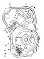
- the parts summarized in the frame 38 according to FIG. 1 form an actuator or the load adjustment device, which are combined in one structural unit.
- the load adjustment device includes a servomotor or electric motor 14 which is connected to a throttle valve 9 via a four-bar linkage 16.
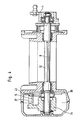
- FIGS. 2 to 5 show the four-bar transmission 16 in detail, while in FIG. 1 only the functional principle of the four-bar transmission 16 is illustrated. For this reason, some transmission parts have been omitted in FIG. 1 for the sake of simplicity.
- the electric motor 14 has an output shaft 40 on the output side with a pinion 41 which is in engagement with a gearwheel segment 50.
- the gear segment 50 is part of a first link 51, which on the outside of the throttle valve housing 30 in a defined Angular range between an upper and a lower stop 59, 60 is pivotally mounted by means of a hinge pin 23.
- the adjustment range of the gear segment 50 and thus the adjustment range of the electric motor 14 is precisely limited and the end position of the throttle valve 9 is precisely defined.
- the stops 59, 60 make it impossible to adjust the throttle valve 9 beyond this position.
- a push rod or a second link 53 is articulated to the first link 51 by means of an articulation pin 20, so that between the gear segment 50 and the articulation point 22 of the second link 53 first link 51 a very large lever arm is formed.
- the end of the second link 53 opposite the articulation point 22 is connected in an articulated manner to a rotor 54 designed as a control element part (see FIG. 1) (see FIG. 2) via a hinge pin 25.
- the rotor 54 is illustrated by a control element part 54.
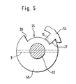
- the rotor or the control element part 54 sits on the outer end of a throttle valve shaft 32 and, as can be seen from FIG. 5, stands in only one direction via a driver element 15 with a stop 27 provided on the throttle valve shaft 32 (in FIG 5 clockwise) in drive connection.
- the stop 27 is formed by a recess or a freewheel segment 26, so that the throttle valve shaft 32 can be adjusted indirectly via an accelerator pedal 1 even when the idle control is not effective.
- the freewheel segment 26 is delimited by a further stop 28.
- the freewheel segment 26 is provided as a recess in a control element part 56, which is arranged on the throttle valve shaft 32 in a rotationally fixed manner or is connected in one piece to the latter. If the electric motor 14 is activated, the four-link mechanism 16 opens the throttle valve 9 arranged on the throttle valve shaft 32 accordingly in the opening direction.
- the rotor 54 is designed as a two-armed lever arm, one lever arm 33 being connected in an articulated manner to the second link 53 via the hinge pin 25 and the other lever arm 34 being able to be brought into abutment against an adjustable stop 35.
- the adjustable stop 35 consists of a bolt 37 arranged in a cylindrical housing 36, which can be adjusted against a spring 39 accommodated in the housing 36.
- the adjustable stop 35 has to adjust the object, the rotor not in the idle position LL not for failure of the control electronics 54th
- the throttle valve 9 is thus brought into this position LL not and held there for the situation of the idle- not control range. If the electric motor 14 is actuated, it can adjust the control element part or the rotor 54 against the action of the spring 39 in the idling direction LL min , the throttle valve 9 being adjusted via the spring 12. Further, the throttle valve 9 can in Aufregelraum to the stop LL start 61 adjust, the modulation of the electric motor 14 via the control device 17.
- the biasing force of the spring 39 arranged in the housing 36 can be changed by an adjusting screw provided in the housing 36.
- the transmission ratio of the articulated gear 16 between the output of the electric motor 14 and the throttle valve shaft 32 is greater than 1:20, although it can also be significantly larger, for example 1:37, due to the advantageous arrangement of the gear segment 50.
- FIG. 1 shows the basic function of the load adjustment device in the case of an idle control actuator in the function of the idle control in the emergency running position.
- the load adjustment device can be adjusted via an accelerator pedal 1 which, when actuated, shifts an accelerator pedal lever 2 between an idle stop LL and a full load stop VL.
- the lever 2 is connected to a driver 4 by means of a throttle cable 3, so that when the accelerator pedal 1 is actuated, the driver 4 is displaced in the direction of the full load stop VL.
- a return spring 5 is connected to the driver 4, which prestresses it in the idling direction LL.
- Two further return springs 6a and 6b bias them in the idling direction LL.
- the return springs 6a and 6b are designed so that they have redundant effects on the return drive.
- the driver 4 rests against the idle stop LL assigned to it.
- the driver 4 can also be pulled in the direction of the idle stop LL by means of an automatic train 7 of a transmission not shown in the drawing.
- the driver 4 interacts directly with a first control element part 56, which serves to adjust a throttle valve 9 of an internal combustion engine, not shown in the drawing.
- the control element 56 is only shown schematically in FIG. 1 and can correspond to the throttle valve shaft 32 shown in FIGS. 2 to 5.
- the end of the driver 4 facing away from the throttle cable 3 is provided with a recess 10 into which the end of the first control element part 56 engages.
- To the recess 10 of the driver 4 includes a stop 28 to come against the driver 4 to the plant, when the accelerator pedal 1 from the idle stop 28 min to - adjusted by the idle position not beyond.
- a spring 12 which is connected at one end to a fixed point 29 and at the other end to the first control element part 56 and acts on it in the idling direction. Due to the fixed arrangement of the spring 12, a direct return of the throttle valve 9 is achieved.
- the spring 12 is effective over the entire adjustment range of the control element part 56 and thus over the entire load range of the internal combustion engine. The spring 12 thus acts in the same direction as the two return springs 6a and 6b.
- the load adjustment device has a second control element part 54, which is connected to an electric motor 14.
- the control element part 54 is also only in FIG. 1 indicated schematically and corresponds to a rotor 54 shown in detail in FIGS. 2 to 5.
- the two control element parts 56 and 54 are not fixedly connected to one another, but are only coupled in one direction of movement, namely in the direction of the emergency emergency position.
- the one end of the second control element part 54 or the rotor 54 has the driver element 15, which can come against the stop 27 provided on the first control element part 56 if an electronic control device 17 belonging to the load adjustment device fails.
- the second control element part 54 is assigned to the throttle valve shaft 32.
- an actuating element or a spring 39 is provided which, via the second control element part or the rotor 54, adjusts the first control element part 56 to the idle emergency position LL not by means of the driving element 15 which only acts in one direction.
- the electronic control device 17 is schematically indicated in Figure 1, which contains conditioning, logic and control circuits.
- the control device 17 stores values for vehicle adaptation and processes the digital or digitized values of various input variables, which then take over the desired position of the throttle valve 9 via an analog part.
- Acting with the electronic control device 17 is an actual value detection device 18 ′ belonging to the first control element part 56 as well as an assigned to the second control element part 54, which determines the respective position of this control element part or of the rotor 54 Actual value detection device 18 together.
- the electronic control device 17 also detects signals via an idle contact 19, which is activated by the driver 4, when the latter comes to rest against the idle stop LL assigned to it.
- the electronic control device 17 serves the purpose of building up a safety logic relating to the control of the first and second control element parts 54, 56. As soon as the electronic control device 17 or the electric motor 14 no longer function properly, the control element part 56 is not moved into the idle emergency position LL by the spring 39, which is biased in the direction of the maximum idle position, and thereby the throttle valve 9 is adjusted into the corresponding position.
- the control element part 56 Due to the movement of the driver 4 in the upward direction, the control element part 56 is adjusted and thus also the throttle valve 9.
- the position of the first control element part 56 which is connected in a rotationally fixed manner to the throttle valve shaft 32, is detected by an actual value detection device 18 ′ assigned to the throttle valve shaft 32, which detects there is a potentiometer 43 arranged in the throttle valve housing 30 and a wiper connected in a rotationally fixed manner to the throttle valve shaft 32.
- the actual value detection device 18 passes this information on to the control device 17, which ensures that the electric motor 14 is no longer activated outside the idle control range.
Landscapes
- Engineering & Computer Science (AREA)
- Chemical & Material Sciences (AREA)
- Combustion & Propulsion (AREA)
- Mechanical Engineering (AREA)
- General Engineering & Computer Science (AREA)
- Control Of Throttle Valves Provided In The Intake System Or In The Exhaust System (AREA)
Applications Claiming Priority (2)
| Application Number | Priority Date | Filing Date | Title |
|---|---|---|---|
| DE4014507 | 1990-05-07 | ||
| DE4014507A DE4014507A1 (de) | 1990-05-07 | 1990-05-07 | Lastverstelleinrichtung |
Publications (3)
| Publication Number | Publication Date |
|---|---|
| EP0455877A2 true EP0455877A2 (fr) | 1991-11-13 |
| EP0455877A3 EP0455877A3 (en) | 1992-02-26 |
| EP0455877B1 EP0455877B1 (fr) | 1995-02-01 |
Family
ID=6405810
Family Applications (1)
| Application Number | Title | Priority Date | Filing Date |
|---|---|---|---|
| EP90124326A Expired - Lifetime EP0455877B1 (fr) | 1990-05-07 | 1990-12-15 | Dispositif de réglage de charge |
Country Status (2)
| Country | Link |
|---|---|
| EP (1) | EP0455877B1 (fr) |
| DE (2) | DE4014507A1 (fr) |
Cited By (5)
| Publication number | Priority date | Publication date | Assignee | Title |
|---|---|---|---|---|
| WO1998027326A1 (fr) * | 1996-12-16 | 1998-06-25 | Robert Bosch Gmbh | Dispositif d'etranglement pour moteur a combustion interne |
| EP1024268A3 (fr) * | 1999-01-29 | 2000-12-27 | Ford Motor Company | Commande électronique de papillon avec mécanisme de défaut réglable |
| EP1099841A3 (fr) * | 1999-11-10 | 2002-04-10 | Visteon Global Technologies, Inc. | Système de commande électronique de papillon avec mécanisme de sécurité à deux ressorts |
| EP1170487A3 (fr) * | 2000-07-05 | 2002-05-08 | Visteon Global Technologies, Inc. | Système de commande électronique de papillon à frottement et usure réduits |
| EP1219802A3 (fr) * | 2000-12-28 | 2002-12-11 | Visteon Global Technologies, Inc. | Corps de papillon commandé électroniquement avec mécanisme de sécurité à faible friction |
Family Cites Families (5)
| Publication number | Priority date | Publication date | Assignee | Title |
|---|---|---|---|---|
| US4462357A (en) * | 1982-08-30 | 1984-07-31 | General Motors Corporation | Throttle system |
| DE3641244C3 (de) * | 1986-12-03 | 1995-02-23 | Vdo Schindling | Anordnung für ein Kraftfahrzeug |
| DE3815735A1 (de) * | 1988-05-07 | 1989-11-16 | Vdo Schindling | Lastverstelleinrichtung |
| DE3918853A1 (de) * | 1989-06-09 | 1990-12-13 | Pierburg Gmbh | Elektrisch ansteuerbare drosselklappenbetaetigungseinrichtung fuer brennkraftmaschinen |
| JPH0385337A (ja) * | 1989-08-29 | 1991-04-10 | Mitsubishi Electric Corp | 機関のスロットル弁制御装置 |
-
1990
- 1990-05-07 DE DE4014507A patent/DE4014507A1/de not_active Withdrawn
- 1990-12-15 DE DE59008419T patent/DE59008419D1/de not_active Expired - Fee Related
- 1990-12-15 EP EP90124326A patent/EP0455877B1/fr not_active Expired - Lifetime
Cited By (5)
| Publication number | Priority date | Publication date | Assignee | Title |
|---|---|---|---|---|
| WO1998027326A1 (fr) * | 1996-12-16 | 1998-06-25 | Robert Bosch Gmbh | Dispositif d'etranglement pour moteur a combustion interne |
| EP1024268A3 (fr) * | 1999-01-29 | 2000-12-27 | Ford Motor Company | Commande électronique de papillon avec mécanisme de défaut réglable |
| EP1099841A3 (fr) * | 1999-11-10 | 2002-04-10 | Visteon Global Technologies, Inc. | Système de commande électronique de papillon avec mécanisme de sécurité à deux ressorts |
| EP1170487A3 (fr) * | 2000-07-05 | 2002-05-08 | Visteon Global Technologies, Inc. | Système de commande électronique de papillon à frottement et usure réduits |
| EP1219802A3 (fr) * | 2000-12-28 | 2002-12-11 | Visteon Global Technologies, Inc. | Corps de papillon commandé électroniquement avec mécanisme de sécurité à faible friction |
Also Published As
| Publication number | Publication date |
|---|---|
| EP0455877B1 (fr) | 1995-02-01 |
| DE59008419D1 (de) | 1995-03-16 |
| DE4014507A1 (de) | 1991-11-14 |
| EP0455877A3 (en) | 1992-02-26 |
Similar Documents
| Publication | Publication Date | Title |
|---|---|---|
| EP0413082B1 (fr) | Dispositif de réglage de charge | |
| DE69103002T2 (de) | Drosselklappe. | |
| EP1379752A1 (fr) | Dispositif pour l'actionnement automatique de la portiere d'un vehicule | |
| DE4141104C2 (de) | Vorrichtung zur Verstellung einer Drosselklappe | |
| DE3831257A1 (de) | Einrichtung zur steuerung des oeffnungsgrades eines drosselventils an einem fahrzeugmotor | |
| DE3927004A1 (de) | Lastverstelleinrichtung | |
| EP0402521B1 (fr) | Dispositif de réglage de charge | |
| EP1111227B1 (fr) | Soupape de re-circulation de gaz d'échappement | |
| EP0455877B1 (fr) | Dispositif de réglage de charge | |
| DE10213249B4 (de) | Betätigungsmechanismus für Feststellbremsen | |
| DE10081962B4 (de) | Elektromechanische Betätigungseinrichtung für ein Kraftfahrzeuggetriebe | |
| EP1081320A1 (fr) | Serrure pour une porte d'automobile ou similaire | |
| DE10042191B4 (de) | Kraftfahrzeug-Türschloß mit gesteuertem Stellelement | |
| EP0456904B1 (fr) | Dispositif de réglage de la puissance | |
| DE102007008977B4 (de) | Verfahren und Vorrichtung zum Steuern und/oder Regeln einer automatisierten Kupplung | |
| EP0478883A2 (fr) | Dispositif de réglage de charge | |
| DE68904644T2 (de) | Drosselklappenkontrolleinrichtung fuer einen verbrennungsmotor. | |
| EP0455880B2 (fr) | Dispositif de réglage de charge | |
| DE4033802A1 (de) | Lastverstelleinrichtung | |
| EP0455882B1 (fr) | Dispositif de réglage pour un papillon des gaz | |
| DE4005905A1 (de) | Elektromotorisch betaetigbare leistungssteuervorrichtung einer brennkraftmaschine | |
| EP4058694B1 (fr) | Actionneur et dispositif pour actionner un frein de stationnement d'une boîte de vitesses automatique de véhicule automobile à l'aide d'un actionneur de ce type ainsi que véhicule automobile équipé de ce dispositif | |
| EP0570623A2 (fr) | Dispositif d'ajustement de papillon d'admission | |
| EP0455883B1 (fr) | Dispositif de réglage pour un papillon des gaz | |
| DE9007817U1 (de) | Lastverstelleinrichtung |
Legal Events
| Date | Code | Title | Description |
|---|---|---|---|
| PUAI | Public reference made under article 153(3) epc to a published international application that has entered the european phase |
Free format text: ORIGINAL CODE: 0009012 |
|
| AK | Designated contracting states |
Kind code of ref document: A2 Designated state(s): DE FR GB IT SE |
|
| PUAL | Search report despatched |
Free format text: ORIGINAL CODE: 0009013 |
|
| AK | Designated contracting states |
Kind code of ref document: A3 Designated state(s): DE FR GB IT SE |
|
| 17P | Request for examination filed |
Effective date: 19920115 |
|
| 17Q | First examination report despatched |
Effective date: 19930714 |
|
| GRAA | (expected) grant |
Free format text: ORIGINAL CODE: 0009210 |
|
| AK | Designated contracting states |
Kind code of ref document: B1 Designated state(s): DE FR GB IT SE |
|
| ET | Fr: translation filed | ||
| REF | Corresponds to: |
Ref document number: 59008419 Country of ref document: DE Date of ref document: 19950316 |
|
| ITF | It: translation for a ep patent filed | ||
| GBT | Gb: translation of ep patent filed (gb section 77(6)(a)/1977) |
Effective date: 19950406 |
|
| PLBE | No opposition filed within time limit |
Free format text: ORIGINAL CODE: 0009261 |
|
| STAA | Information on the status of an ep patent application or granted ep patent |
Free format text: STATUS: NO OPPOSITION FILED WITHIN TIME LIMIT |
|
| 26N | No opposition filed | ||
| PGFP | Annual fee paid to national office [announced via postgrant information from national office to epo] |
Ref country code: GB Payment date: 19971113 Year of fee payment: 8 Ref country code: FR Payment date: 19971113 Year of fee payment: 8 |
|
| PGFP | Annual fee paid to national office [announced via postgrant information from national office to epo] |
Ref country code: DE Payment date: 19971118 Year of fee payment: 8 |
|
| PGFP | Annual fee paid to national office [announced via postgrant information from national office to epo] |
Ref country code: SE Payment date: 19971124 Year of fee payment: 8 |
|
| PG25 | Lapsed in a contracting state [announced via postgrant information from national office to epo] |
Ref country code: GB Free format text: LAPSE BECAUSE OF NON-PAYMENT OF DUE FEES Effective date: 19981215 |
|
| PG25 | Lapsed in a contracting state [announced via postgrant information from national office to epo] |
Ref country code: SE Free format text: LAPSE BECAUSE OF NON-PAYMENT OF DUE FEES Effective date: 19981216 |
|
| GBPC | Gb: european patent ceased through non-payment of renewal fee |
Effective date: 19981215 |
|
| PG25 | Lapsed in a contracting state [announced via postgrant information from national office to epo] |
Ref country code: FR Free format text: LAPSE BECAUSE OF NON-PAYMENT OF DUE FEES Effective date: 19990831 |
|
| REG | Reference to a national code |
Ref country code: FR Ref legal event code: ST |
|
| PG25 | Lapsed in a contracting state [announced via postgrant information from national office to epo] |
Ref country code: DE Free format text: LAPSE BECAUSE OF NON-PAYMENT OF DUE FEES Effective date: 19991001 |
|
| PG25 | Lapsed in a contracting state [announced via postgrant information from national office to epo] |
Ref country code: IT Free format text: LAPSE BECAUSE OF NON-PAYMENT OF DUE FEES;WARNING: LAPSES OF ITALIAN PATENTS WITH EFFECTIVE DATE BEFORE 2007 MAY HAVE OCCURRED AT ANY TIME BEFORE 2007. THE CORRECT EFFECTIVE DATE MAY BE DIFFERENT FROM THE ONE RECORDED. Effective date: 20051215 |