EP0455514B1 - Sheet feeder - Google Patents
Sheet feeder Download PDFInfo
- Publication number
- EP0455514B1 EP0455514B1 EP91304056A EP91304056A EP0455514B1 EP 0455514 B1 EP0455514 B1 EP 0455514B1 EP 91304056 A EP91304056 A EP 91304056A EP 91304056 A EP91304056 A EP 91304056A EP 0455514 B1 EP0455514 B1 EP 0455514B1
- Authority
- EP
- European Patent Office
- Prior art keywords
- sheet
- vacuum
- stack
- sheets
- shuttle plate
- Prior art date
- Legal status (The legal status is an assumption and is not a legal conclusion. Google has not performed a legal analysis and makes no representation as to the accuracy of the status listed.)
- Expired - Lifetime
Links
Images


Classifications
-
- B—PERFORMING OPERATIONS; TRANSPORTING
- B65—CONVEYING; PACKING; STORING; HANDLING THIN OR FILAMENTARY MATERIAL
- B65H—HANDLING THIN OR FILAMENTARY MATERIAL, e.g. SHEETS, WEBS, CABLES
- B65H5/00—Feeding articles separated from piles; Feeding articles to machines
- B65H5/02—Feeding articles separated from piles; Feeding articles to machines by belts or chains, e.g. between belts or chains
- B65H5/021—Feeding articles separated from piles; Feeding articles to machines by belts or chains, e.g. between belts or chains by belts
- B65H5/025—Feeding articles separated from piles; Feeding articles to machines by belts or chains, e.g. between belts or chains by belts between belts and rotary means, e.g. rollers, drums, cylinders or balls, forming a transport nip
-
- B—PERFORMING OPERATIONS; TRANSPORTING
- B65—CONVEYING; PACKING; STORING; HANDLING THIN OR FILAMENTARY MATERIAL
- B65H—HANDLING THIN OR FILAMENTARY MATERIAL, e.g. SHEETS, WEBS, CABLES
- B65H1/00—Supports or magazines for piles from which articles are to be separated
- B65H1/04—Supports or magazines for piles from which articles are to be separated adapted to support articles substantially horizontally, e.g. for separation from top of pile
- B65H1/06—Supports or magazines for piles from which articles are to be separated adapted to support articles substantially horizontally, e.g. for separation from top of pile for separation from bottom of pile
-
- B—PERFORMING OPERATIONS; TRANSPORTING
- B65—CONVEYING; PACKING; STORING; HANDLING THIN OR FILAMENTARY MATERIAL
- B65H—HANDLING THIN OR FILAMENTARY MATERIAL, e.g. SHEETS, WEBS, CABLES
- B65H3/00—Separating articles from piles
- B65H3/08—Separating articles from piles using pneumatic force
- B65H3/12—Suction bands, belts, or tables moving relatively to the pile
- B65H3/122—Suction tables
-
- B—PERFORMING OPERATIONS; TRANSPORTING
- B65—CONVEYING; PACKING; STORING; HANDLING THIN OR FILAMENTARY MATERIAL
- B65H—HANDLING THIN OR FILAMENTARY MATERIAL, e.g. SHEETS, WEBS, CABLES
- B65H2511/00—Dimensions; Position; Numbers; Identification; Occurrences
- B65H2511/10—Size; Dimensions
-
- B—PERFORMING OPERATIONS; TRANSPORTING
- B65—CONVEYING; PACKING; STORING; HANDLING THIN OR FILAMENTARY MATERIAL
- B65H—HANDLING THIN OR FILAMENTARY MATERIAL, e.g. SHEETS, WEBS, CABLES
- B65H2511/00—Dimensions; Position; Numbers; Identification; Occurrences
- B65H2511/20—Location in space
Definitions
- This invention relates broadly to Sheet Feeders, and more specifically to Sheet Feeders of a type for feeding individually, forward-most sheets, from a pile or stack, usually to clamps of endless-chain conveyors.
- Such sheet feeder comprises a vacuum shuttle plate for transporting single sheets from the stack to an additional conveyor and a first blocking means for holding back other sheets of the stack (GB-A-1 512 922).
- sheets refer to envelopes as well as to individual sheets and other thin elements.
- US Patent Specification US-A-4546963 discloses a shet feeder having a belt conveyor for transporting sheets from the bottom of a stack, a fixed blocking wall for holding back other sheets of the stack, and a rotating friction roller for holding back an upper sheet while a lower sheet is carried forward by the conveyor.
- Reciprocating vacuum shuttle-plate sheet feeders are well known, with several being shown in U.S. Patent 3,844,551 to Morrison and U.S. Patent 4,657,236 to Hirakawa et al.
- a cycle of operation for these vacuum-type sheet feeding devices is normally approximately as follows: A suction is applied through a shuttle plate to a forward-most sheet in a sheet stack, thereby adhering the forward-most sheet to a sheet-engaging surface of the shuttle plate.
- the shuttle plate then moves in a feed direction carrying the forward-most sheet with it below a rigid blocking gate and delivers this to rollers, or additional conveyors, which then pull the sheet the rest of the way from the stack.
- the suction is turned off and the shuttle plate returns to its normal position at the sheet stack.
- elongated knife gates or other blocking structures, are used to restrain other sheets in the sheet stack from moving with the shuttle plate, while in some such systems the sheet stack rests on one or more ledges from which the bottom sheet is pulled prior to being fed forwardly by the shuttle plate.
- the sheet shuttle feed described in U.S. Patent 3,844,551 to Morrison combines both of these features.
- one difficulty with some prior-art vacuum reciprocating-shuttle-plate sheet feeding devices is that suctions, or partial vacuums, applied by shuttle plates thereof, bleed through forward-most sheets and cause second-from-forward sheets to adhere to the forward-most sheets. When this happens, two sheets are sometimes fed forwardly by the shuttle plates.
- a suction groove should be arranged to pull a sheet at a position as close to the center thereof as possible. It is therefore, an object of this invention to provide a vacuum shuttle plate sheet feeder in which the position at which vacuum is applied relative to a hopper and a shuttle plate can be varied so that the shuttle plate can be tailored to fit various size and shaped envelopes.
- the sheet feeder is characterized by a second blocking means positioned between the first blocking means and the additional conveyor to separate any double sheet fed past the first blocking means, the second blocking means comprising two singulator separators positioned on opposite sides of a vacuum groove in the shuttle plate to form singulator gaps between the singulator separator and shoulders formed on the shuttle plate on opposite sides of the vacuum groove.
- a reciprocating vacuum shuttle-plate sheet feeder employs a friction-type singulator between a throat knife gate and a downstream additional conveyor.
- the friction-type singulator comprises two resilient fixed rollers which form gaps with shoulders positioned on opposite sides of a vacuum grove of a vacuum shuttle plate. Gaps formed by the knife gate and the high-friction rollers with the shuttle plate can be adjusted together or independently.
- the shuttle plate itself comprises an underlying vacuum manifold and interchangeable top-surface plates, one of which has vacuum openings therein.
- the positions of the vacuum openings in the shuttle plate can be changed while still keeping these openings in communication with the vacuum manifold and not changing the position and/or size of the shuttle plate.
- the sheet feeder of this invention includes a feed tray for inserting fed sheets into a gripper jaw of a clamp mounted on an endless conveyor, ensuring that sheets fed from a sheet stack by the shuttle plate are properly inserted into the gripper jaw.
- the feed tray comprises a continuously driven endless conveyor belt against which a floating feed roller is biased. The position of the floating feed roller along the belt can be varied so that it can be placed approximately the length of a sheet from a stopped clamp on the endless conveyor. Sheets fed to the feed tray by the shuttle plate are further conveyed by the endless conveyor and the floating feed roller firmly and accurately into the gripper jaw of the clamp.
- Guides of a hopper of the sheet feeder include a thumb mechanism which provides resistance to falling sheets so that a forward-most sheet does not have a great deal of pressure on it.
- a sheet feeding system 10 includes generally a vacuum reciprocating shuttle sheet feeder 12, and a sheet feeding transition tray 14.
- the entire system has support structures 16 which are rigidly attached together and supported from a floor (not shown). Included in the support structure 16 are horizontal surfaces 16a, a rear mounting bar 16b, feed path guides 16c, a hopper transverse support bar 16d, a separator transverse support bar 16e, etc. It will be understood that there are other support structures, such as bracket 18 for supporting the separator mechanism transverse support bar 16e from the horizontal surface 16a and a bracket 19 for supporting the hopper transverse support bar 16d from the horizontal surface 16a, which are not further described but yet which can be seen in the drawings.
- the vacuum reciprocating shuttle sheet feeder 12 includes a hopper 20 which is defined by rear hopper guides 22 and 24 and front hopper guides 26 and 28.
- Each of the rear hopper guides 22 and 24 respectively includes a pile lifter 30 and 32 and one of the front hopper guides 26 and 28 includes a thumb mechanism 29.
- the purpose of the rear pile lifters 30 and 32 is to lift rear corners of sheets 36 held in the hopper 20 to compensate for warped sheets and to provide better contact for a forward-most sheet 56 to a vacuum groove 186 described below. It can be seen in Fig.
- the rear hopper guides 22 and 24 can be laterally adjusted along the hopper transverse support bar 16d by means of clamps 38 and that the hopper transverse support bar 16d, in turn, can be adjusted along the rear mounting bar 16b and along a slot 40 in the horizontal surface 16a by means of clamps 42 and 44.
- the front hopper guides 26 and 28 have similar lateral adjustments, with the front hopper guide 26 being adjustable along the separator mechanism transverse support bar 16e by means of a clamp 46 which is fastened to the separator mechanism transverse support bar 16e by means of a set screw operated by a lever 48.
- Guides 34 and 36 help support the sheets.
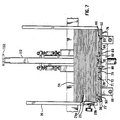
- the thumb mechanism 29, shown in Fig. 7, is positioned about an inch above a top surface 50 of a reciprocating shuttle plate 52 about one and one half inches from a front corner of a sheet stack 54. Positioned in this manner, this thumb mechanism 29 supports a forward front edge of the sheet, or envelope, stack 54, shown in phantom in Fig. 1, above a forward-most sheet 56, but yet allows the forward-most sheet 56 and several sheets above the forward-most sheet to fall completely down on the top surface 50 of the shuttle plate.
- the purpose of the thumb mechanism 29 is to lift and separate sheets in a manner analogous to a person "thumbing" through a stack of paper, thus, removing weight from the forward-most sheet 56.
- the thumb mechanism 29 has a convex rounded surface 29a, much in the shape of a person's thumb. It is made of metal in a preferred embodiment and can be clamped to a shaft 29b to be placed at any angle into the sheet stack 54.
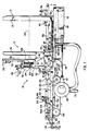
- the shuttle plate 52 as depicted in Figs. 1-3 is in its rear most position, to the right.
- the shuttle plate is reciprocated between this rear-most position and a forwardly-most position (to the left as depicted in Figs. 1-3) by a shuttle plate drive shaft 58 which is coupled between a shuttle plate bracket 60 and a rotatable clamp 62.
- a drive belt 64 drives the rotatable clamp 62
- the shuttle-plate drive shaft 58 is moved from right to left, and back to right, thereby reciprocating the shuttle plate 52 to which the shuttle-plate bracket 60 is attached.
- the shuttle plate reciprocally rides on shuttle-plate guide shafts 66 which are part of the supporting structure.
- the drive belt 64 drives the rotatable clamp 62, it also operates a valve 68 which controls vacuum from an inlet line 70 to a cavity 71 of a shuttle-plate vacuum manifold 72.
- the manifold 72 is bolted to an underside of a shuttle-plate base 74 to which are bolted, on an upper side thereof, shuttle-plate upper panels 76, 78, 79, 81, 82, 84 and 85.
- the shuttle-plate upper panels are of various sizes in the depicted embodiment as a matter of convenience, however, where appropriate, they could be of equal size.
- a primary reason for these removable upper panels is to allow a vacuum-groove panel 81 to be moved laterally, that is, upwardly and downwardly as viewed in Fig. 2.
- the vacuum-groove panel 81 When the vacuum-groove panel 81 is moved laterally, it remains in communication with the manifold cavity 71 through holes in the shuttle-plate base 74, while other panels which are placed over the manifold cavity 71 do not allow transmission of a vacuum therethrough.
- the shuttle-plate base 74 also has an opening or openings therethrough corresponding to the manifold 72.
- Support-structure upper panels 88, 89, and 90 are special plates, each of these having an oblong opening 92 therein to allow a driven feed roller 94 to come into contact with an idler feed roller 96, forming a nip therebetween which is basically an additional conveyor for gripping a forward-most sheet 56 when it is separated by vacuum applied to the shuttle plate 52 and thereby pulled from under the stack 54, as will be described below.
- Support-structure panels 80, 83, 86, 87, 88, 89 and 90 serve mainly as guards to protect persons from being pinched by moving mechanisms and to support sheets.
- Clamp 46 also serves as a guard. It can be noted in Fig.
- the support-structure panels 80, 83 and 86 are at a higher level than the shuttle-plate panels 79, 82 and 85 so that these shuttle-plate panels can slide thereunder. It can be seen in Fig. 7 that the vacuum groove panel 81 is taller than adjacent panels which enhances its vacuum seal with the forward-most sheet 56.
- the reciprocating vacuum shuttle sheet feeder 12 also includes a sheet separator 98 which is mounted on the separator mechanism transverse support bar 16e by means of a set screw operated manually by a lever 100.
- a main frame 102 of the sheet separator 98 includes a block 104 and a channel member 106. Riding in a channel 108 of the channel member 106 are a friction singulator roller support bar 110 and a knife gate 112. Each of these members is slideably moveable in the channel 108, but is held in the channel by means of screws 114 embedded in the channel member 106 which pass through slots in the singulator roller support bar 110 and the knife gate 112.
- High-friction rollers 118 and 120 are mounted on a downstream, or front, side of the singulator roller support bar 110 by means of a hub 122 and their positions relative to the block 104 can be adjusted by means of a knob 124 which screws a screw 126 into and out of the block 104 to thereby move a bracket 128 which is positioned on an extension of the screw 126.
- a toggle clamp 130 which is attached to and rotates on bracket 128 includes threads to engage threads of the extension of the screw 126. These threads are the same hand but of different pitch than those of block 104, or they can be of opposite hand, to effect a relative motion between block 104 and the bracket 128 when the knob 124 is rotated.
- the toggle clamp 130 can be used to quickly raise the singulator roller support bar 110, the knife gate 112, and idler feed rollers 96 by allowing the bracket 128 to quickly be forced upwardly on the extension of the screw 126 by means of a compression spring 131 mounted on the extension of the screw 126.
- the toggle clamp 130 is rotated downwardly, as shown in Fig. 5, so that the bracket 128 is locked in a fixed position, relatively close to the block 104.
- the high-friction rollers 118 and 120 under normal operation do not roll, but rather are in fixed positions. However, they can be loosened and rolled, or rotated, to new positions so as to present fresh wear surfaces to sheets, thereby adjusting for wear.
- the high-friction rollers 118 and 120 are constructed of a material having a coefficient of friction such that when the high-friction rollers 118 and 120 impinge on a top sheet, such as an envelope, of a sheet pair double passing thereunder a friction force between the high-friction rollers 118 and 120 and the top sheet is greater than the friction force between the top sheet and a bottom sheet of the pair so that the top sheet is stripped from the bottom sheet, with the bottom sheet being transported further and the top sheet being held by the high-friction rollers 118 and 120.
- a seventy durometer urethane is employed.
- the knife gate 112 can also be moved relative to the singulator roller support bar 110 by means of a knob 132 journaled for rotation in a bracket 134 attached to the knife gate 112 for rotating a screw 136 having male threads which mate with female threads in a bracket 138 attached to the singulator roller support bar 110.
- a knob 132 journaled for rotation in a bracket 134 attached to the knife gate 112 for rotating a screw 136 having male threads which mate with female threads in a bracket 138 attached to the singulator roller support bar 110.
- idler-feed-roller followers 140 Mounted on outer side surfaces of the channel member 106 are idler-feed-roller followers 140 which are free to move longitudinal, upwardly and downwardly as viewed in Figs. 4-6, because slots 142 therein allow such movement on mounting bolts 144.
- the idler-feed-roller followers 140 are biased downwardly by means of compression springs 148 positioned on extensions of screws 150 having threads which mesh with females threads of the idler-feed-roller followers 140. By rotating knobs 152 of the screws 150, tension of the springs 148 can be adjusted for varying pressures with which the idler-feed-rollers 96 are urged downwardly against the driven feed rollers 94.
- the idler-feed-rollers 96 are mounted on the lower end of the idler-feed-roller followers 140.
- this tray Describing next the sheet-feeding transition tray 14 (Fig. 1), this tray comprises a horizontal surface 16a, having a ramp 153, which is part of the support structure 16 but which defines a slot 154 (Fig. 2) therein in which is positioned a continuously running conveyor belt 156 supported by a fixed plate 158.
- the sheet-feeding transition tray 14 also comprises floating feed rollers 160 which are mounted on the rear mounting bar 16b by means of clamps 162 and which are biased on levers 164 by means of springs 166 toward the conveyor belt 156. In this regard, by rotating knobs 168 of the clamps 162 and moving the clamps 162 along the rear mounting bar 16b, the positions of the floating feed rollers 160 along the conveyor belt 156 can be changed.
- the conveyor belt 156 is continually driven by pulleys 170 which, in turn, are driven by the drive belt 64 as can be seen in Fig. 3.
- pulleys 170 which, in turn, are driven by the drive belt 64 as can be seen in Fig. 3.
- a sheet enters bites between the floating feed rollers 160 and the conveyor belt 156 it is automatically moved to the left as viewed in Fig. 1.
- This entire structure is positioned so that a sheet 172 (Fig. 1) exiting from the sheet-feeding transition tray 14 will be fed exactly into a jaw 174 of a clamp 176 mounted on an endless conveyor chain 178.
- an operator first determines the best location of the vacuum groove panel 81 above the manifold 72. To do this, he observes the size of sheets to be fed and the location of objects on the sheet. For example, if the sheet is an envelope with a window, he will want to place the shuttle vacuum-groove panel 81 in a location such that it will not suck on, and perhaps deform, such a window. He does this by screwing particular shuttle-plate and support-structure panels 76-90 off and then remounting them with the shuttle vacuum-groove panel 81 in an appropriate position above the cavity 71 of the vacuum manifold 72.
- the operator adjusts positions of the rear and front hopper guides 22, 24, 26 and 28 so that they appropriately guide the edges of a sheet stack to be placed therein.
- the rear hopper guides 22 and 24 are adjusted laterally on the hopper transverse support bar 16d, and in the direction of sheet travel by sliding the hopper transverse support bar 16d along the rear mounting bar 16b and in the slot 40 of the support structure 16.
- the clamp 46 is moved along the separator mechanism transverse support bar 16e to laterally adjust the front hopper guide 26.
- the front hopper guide 28 is a similar adjustment for the front hopper guide 28.
- the positions of the floating feed rollers 160 on the sheet feeding transition tray 14 are adjusted in the direction of sheet travel.
- a leading edge of the sheet 172 will not be crammed too strongly into the jaw 174 and thereby distorted, nor will it not be shoved far enough into the jaw 174 and thereby cause problems downstream.
- the next adjustment that must be made is to the sheet separator 98 so that the separator separates only a forward-most sheet 56 from the sheet stack 54 when the shuttle plate 52 is reciprocated in the sheet separating direction 180.
- First the lateral position of the sheet separator 98 is adjusted along the separator mechanism transverse support bar 16e, utilizing the set screw lever 100, so that the knife gate 112 is lined up with a vacuum groove 186 of the vacuum-groove panel 81.
- the friction singulator roller support bar 110 and the knife gate 112 are set to their appropriate vertical positions. These vertical adjustments are carried out by first closing the toggle clamp 130, that is, rotating it downwardly as shown in Fig.
- the knife gate 112 is moved out of the way by rotating the knob 132 so that a separating lower end 182 thereof does not obstruct movement of forward-most sheets in the sheet separating direction 180.
- a single sheet of the type to be separated is laid in the hopper 20 and slid under the separating lower end 182 of the knife gate 112 until it contacts the high-friction rollers 120. If it does not contact these, these are lowered by rotating the knob 124 on the sheet separator 98 to thereby move the screw 126, the bracket 128, and the friction singulator roller support bar 110 downwardly until such contact is made.
- the high-friction rollers 118 and 120 are spaced above shoulders 184 of the shuttle vacuum-groove panel 81 on opposite sides of a vacuum groove 186 thereof, such that one sheet can pass between a singulator gap 188 formed therebetween.
- the knife gate 112 is adjusted downwardly by rotating the knob 132, thereby moving the knife gate 112 downwardly relative to the friction singulator roller support bar 110.
- the separator lower end 182 of the knife gate 112 is adjusted so that it is barely in position to block a single sheet trying to pass thereunder without any vacuum applied to the vacuum groove 186 of the shuttle vacuum-groove panel 81. In this position, the knife gate 112 will block movement of second-from forward sheets in the sheet separating direction 180, but the forward-most sheet 56 will be pulled downwardly by vacuum applied in the vacuum groove 186 so that it can clear the separating lower end 182 of the knife gate 112 to move in the sheet separating direction 180.
- the second-from-forward sheet, immediately above the forward-most sheet, will not have a significant vacuum applied to it and therefore will not be lowered below the separating lower end 182 of the knife gate 112 and, therefore, cannot follow the forward-most sheet in the sheet separating direction 180.
- the space relationships in the sheet separating direction 180 of a feed nip 190 formed between the driven feed rollers 94 and the idler feed rollers 96 and the singulator gap 188 formed between the high-friction rollers 118 and 120 and the shoulders 184 on opposite sides of the vacuum groove 186 relative to a throat 192 formed between separator lower end 182 at the knife gate 112 and the vacuum groove 186 should be noted.
- the throat 192 is upstream of the singulator gap 188 which, in turn, is upstream of the feed nip 190.
- the idler feed roller 96, the high-friction rollers 118 and 120, and the separating lower end 182 of the knife gate 112 can be quickly raised relative to the shuttle-vacuum groove panel 81, when necessary, without changing their relative relationships one to the other by raising the toggle clamp 130.
- a stack 54 of sheets is placed in the hopper 20 and the sheet feeding system is turned on.
- the drive belt 64 rotates the rotatable clamp 62 to reciprocate the shuttle plate 52.
- the drive belt 64 operates the valve 68 to apply a vacuum to the vacuum groove 186 every time the shuttle plate 52 is approaching its right-most position as shown in Fig. 1, and to relieve the vacuum when the shuttle plate 52 is in a position for feeding a forward-most sheet into a feed nip 190. It appears that there is some advantage to turning the vacuum on prior to the shuttle plate 52 reaching its right-most position and drawing a forward-most sheet slightly to the right before feeding it in a sheet separating direction 180 to the left.
- the drive belt 64 continuously drives the conveyor belt 156 of the sheet feeding transition tray 14.
- a vacuum is applied to the vacuum groove 186, the forward-most sheet 56 is pulled slightly downwardly into the throat 192 immediately below the separating lower end 182 of the knife gate 112 and this forward-most sheet is, therefore, allowed to pass under the knife gate 112 with movement in the separating direction 180 of the shuttle plate 52.
- This forward-most sheet will thereby be fed onto the horizontal surface 16a by the ramp 153 thereof and between nips formed by the floating feed rollers 160 and the conveyor belt 156.
- This ramp 153 is part of guard configuration to prevent pinch points and support sheets.
- the continuously driven conveyor belt 156 will thereby pick up the forward-most sheet and transport it into an open jaw 174 of a temporarily stationary chain mounted clamp 176 at which point the sheet will be freed from a last transporting nip between the floating feed roller 160a and the conveyor belt 156.
- the thumb mechanism 29, which provides support for an edge of some sheets in the sheet stack 54 above the forward-most sheet 56, relieves some downward weight pressure on the forward-most sheet 56, but is not sufficiently large, or shaped, to prevent sheets in the sheet stack 54 from falling downwardly and thereby eventually becoming forward-most sheets themselves.
- the placing of the knife gate throat, the friction singulator gap, and the additional conveyor respectively downstream from one another in a series provides a high degree of separation accuracy during each shuttle plate stroke but yet does not require extra mechanical movement of parts and is therefore inexpensive in construction and setup, and is smooth in operation. It has been found that this arrangement is extremely accurate, virtually eliminating all doubles.
- Yet another benefit derived from the sheet-feeding system 10 is that it feeds sheets into jaws of conveyor-mounting clamps accurately, without cramming the sheets into the clamps thereby deforming leading edges of the sheets, but yet ensures that the sheets are sufficiently inserted into the jaws.
Landscapes
- Engineering & Computer Science (AREA)
- Mechanical Engineering (AREA)
- Sheets, Magazines, And Separation Thereof (AREA)
- Delivering By Means Of Belts And Rollers (AREA)
Description
- This invention relates broadly to Sheet Feeders, and more specifically to Sheet Feeders of a type for feeding individually, forward-most sheets, from a pile or stack, usually to clamps of endless-chain conveyors.
- Such sheet feeder comprises a vacuum shuttle plate for transporting single sheets from the stack to an additional conveyor and a first blocking means for holding back other sheets of the stack (GB-A-1 512 922).
- It should be understood that "sheets" as used herein refer to envelopes as well as to individual sheets and other thin elements.
- US Patent Specification US-A-4546963 discloses a shet feeder having a belt conveyor for transporting sheets from the bottom of a stack, a fixed blocking wall for holding back other sheets of the stack, and a rotating friction roller for holding back an upper sheet while a lower sheet is carried forward by the conveyor.
- Reciprocating vacuum shuttle-plate sheet feeders are well known, with several being shown in U.S. Patent 3,844,551 to Morrison and U.S. Patent 4,657,236 to Hirakawa et al. A cycle of operation for these vacuum-type sheet feeding devices is normally approximately as follows: A suction is applied through a shuttle plate to a forward-most sheet in a sheet stack, thereby adhering the forward-most sheet to a sheet-engaging surface of the shuttle plate. The shuttle plate then moves in a feed direction carrying the forward-most sheet with it below a rigid blocking gate and delivers this to rollers, or additional conveyors, which then pull the sheet the rest of the way from the stack. At this point, the suction is turned off and the shuttle plate returns to its normal position at the sheet stack.
- In some such systems, elongated knife gates, or other blocking structures, are used to restrain other sheets in the sheet stack from moving with the shuttle plate, while in some such systems the sheet stack rests on one or more ledges from which the bottom sheet is pulled prior to being fed forwardly by the shuttle plate. The sheet shuttle feed described in U.S. Patent 3,844,551 to Morrison, combines both of these features. In this regard, one difficulty with some prior-art vacuum reciprocating-shuttle-plate sheet feeding devices is that suctions, or partial vacuums, applied by shuttle plates thereof, bleed through forward-most sheets and cause second-from-forward sheets to adhere to the forward-most sheets. When this happens, two sheets are sometimes fed forwardly by the shuttle plates. It is possible to reduce such "double feeds" by reducing the amount of suction applied to the forward-most sheets; however, such a method also reduces the strength with which the shuttle plate holds the forward-most sheet. This sometimes produces "miss feeds," that is, a shuttle stroke that feeds no sheet. By having redundant separators, U.S. Patent 3,844,551 to Morrison allows a sufficiently high vacuum for substantially reducing "miss feeds" while preventing "double feeds" by pulling corners of forward-most sheets from a ledge with a separate suction cup just prior to their being fed. However, this redundancy has a price inasmuch as the structure required to move the separate suction cup is an added expense and its operation causes additional vibrations during overall operation of the sheet feeder. Thus, it is an object of this invention to provide a sheet feeder which reduces the number of "double feeds" and "miss feeds" but yet which does not require the use of a separate reciprocating sheet separator prior to or during movement of a vacuum shuttle plate.
- There is a difficulty in positioning blocking structures in vacuum shuttle-plate sheet feeders employing such blocking structures, or gates, to prevent other sheets from following forward-most sheets. That is, if a blocking structure is positioned too high relative to its shuttle plate, it may allow a second-from-forward sheet to follow the forward-most sheet and if it is too low, it may improperly prevent a thick forward-most sheet from being fed. This problem is magnified when the sheet feeder is used for feeding envelopes. In this regard, it is difficult to separate a forward-most envelope with a throat knife, or other blocking structure, because loose envelope edges and windows tend to catch on the knife. For this reason, when feeding envelopes, it is desirable to have such a blocking structure, or throat knife, in a relatively open position. On the other hand, when such a throat knife is too "open" a double will occur. It is an object of this invention to provide a vacuum shuttle-plate sheet feeder in which a throat knife can be placed in a relatively "open" position so that it can be easily used with envelopes but yet which does not produce an undue number of "double feeds".
- Yet another difficulty with reciprocating vacuum shuttle plate sheet feeders has been that shuttle plates thereof applied suction at fixed locations on forward-most sheets. For example, in a device of U.S. Patent 3,844,551, a suction groove of a shuttle plate thereof is in one position relative to the shuttle plate and a hopper and cannot be moved. A difficulty with such a structure is that a position of its suction groove cannot be tailored to fit different size and shaped envelopes. Thus, the vacuum groove may damage envelope windows if its necessary position happens to coincide with envelope windows, for example. Also, suction-groove positioning may detrimentally affect the accuracy of sheet feeds because when a sheet is pulled too close to an edge thereof it often skews and jams, especially when there is a heavy stack of paper thereon. Ideally, a suction groove should be arranged to pull a sheet at a position as close to the center thereof as possible. It is therefore, an object of this invention to provide a vacuum shuttle plate sheet feeder in which the position at which vacuum is applied relative to a hopper and a shuttle plate can be varied so that the shuttle plate can be tailored to fit various size and shaped envelopes.
- Many previous vacuum shuttle sheet feeders feed envelopes directly to indexed, or momentarily stationary, clamps mounted on endless chain conveyors. Any slippage in conveying such envelopes from bottoms, or forward-most positions, of their stacks to the gripper jaws of such clamps causes an imprecise placement of the envelopes in the jaws which often causes jams or improper feeds downstream thereof. For example, if an envelope is crammed too firmly into a gripper jaw of a clamp, a leading edge of the envelope will be bent, thereby causing problems for later handling of the envelope. On the other hand, if the envelope is not fed far enough into a clamp's gripper jaw, the envelope might be inadequately held when the gripper jaw closes, again causing problems downstream. Thus, it is an object of this invention, to provide a transition structure between a sheet feeder and a gripper jaw of an endless conveyor mounted clamp such that a sheet is fed precisely into the gripper jaw thereof.
- Yet another difficulty with many sheet feeders is that stacks placed in hoppers thereof cause great weight forces pressing downwardly on bottom, or forward-most, sheets therein, making it difficult for shuttle plates and the like to pull these forward-most sheets from the stacks. It is an object of this invention to counteract this downward gravity force acting on forward-most sheets to thereby make it easier for shuttle plates, and similar separating elements, to pull forward-most sheets from stacks.
- According to the invention the sheet feeder is characterized by a second blocking means positioned between the first blocking means and the additional conveyor to separate any double sheet fed past the first blocking means, the second blocking means comprising two singulator separators positioned on opposite sides of a vacuum groove in the shuttle plate to form singulator gaps between the singulator separator and shoulders formed on the shuttle plate on opposite sides of the vacuum groove.
- In an embodiment constructed in accordance with the principles of this invention, a reciprocating vacuum shuttle-plate sheet feeder employs a friction-type singulator between a throat knife gate and a downstream additional conveyor. The friction-type singulator comprises two resilient fixed rollers which form gaps with shoulders positioned on opposite sides of a vacuum grove of a vacuum shuttle plate. Gaps formed by the knife gate and the high-friction rollers with the shuttle plate can be adjusted together or independently.
- The shuttle plate itself comprises an underlying vacuum manifold and interchangeable top-surface plates, one of which has vacuum openings therein. Thus, by interchanging these panels, the positions of the vacuum openings in the shuttle plate can be changed while still keeping these openings in communication with the vacuum manifold and not changing the position and/or size of the shuttle plate.
- The sheet feeder of this invention includes a feed tray for inserting fed sheets into a gripper jaw of a clamp mounted on an endless conveyor, ensuring that sheets fed from a sheet stack by the shuttle plate are properly inserted into the gripper jaw. The feed tray comprises a continuously driven endless conveyor belt against which a floating feed roller is biased. The position of the floating feed roller along the belt can be varied so that it can be placed approximately the length of a sheet from a stopped clamp on the endless conveyor. Sheets fed to the feed tray by the shuttle plate are further conveyed by the endless conveyor and the floating feed roller firmly and accurately into the gripper jaw of the clamp.
- Guides of a hopper of the sheet feeder include a thumb mechanism which provides resistance to falling sheets so that a forward-most sheet does not have a great deal of pressure on it.
- The forgoing and other objects, features and advantages of the invention will be apparent from the following more particular description of a preferred embodiment of the invention, as illustrated in the accompanying drawings in which reference characters refer to the same parts throughout the different views. The drawings are not necessarily to scale, emphasis instead being placed upon illustrating principles of the invention in a clear manner.
- Fig. 1 is a simplified, side, partially sectional, view of a sheet feeder system of this invention;
- Fig. 2 is a top view of the structure of Fig. 1;
- Fig. 3 is a top view taken approximately on line 3-3 in Fig. 1, with many parts being removed for simplification, showing the substructure of the sheet feeder system of Figs. 1 and 2;
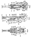
- Fig. 4 is a fragmented elevational front view of a sheet separator mechanism of the system of Figs. 1 and 2;
- Fig. 5 is a side elevational view of the structure of Fig. 4, but also including a driven feed roller and showing a portion of a shuttle plate;
- Fig. 6 is a rear elevational view of the structure of Fig. 5, as seen from a sheet stack; and
- Fig. 7 is a segmented, simplified, partially in cross section, view schematically showing operation of a thumb mechanism of this invention.
- A
sheet feeding system 10 includes generally a vacuum reciprocatingshuttle sheet feeder 12, and a sheet feeding transition tray 14. - The entire system has
support structures 16 which are rigidly attached together and supported from a floor (not shown). Included in thesupport structure 16 arehorizontal surfaces 16a, arear mounting bar 16b,feed path guides 16c, a hoppertransverse support bar 16d, a separatortransverse support bar 16e, etc. It will be understood that there are other support structures, such asbracket 18 for supporting the separator mechanismtransverse support bar 16e from thehorizontal surface 16a and abracket 19 for supporting the hoppertransverse support bar 16d from thehorizontal surface 16a, which are not further described but yet which can be seen in the drawings. - The vacuum reciprocating
shuttle sheet feeder 12 includes ahopper 20 which is defined byrear hopper guides front hopper guides pile lifter thumb mechanism 29. The purpose of therear pile lifters sheets 36 held in thehopper 20 to compensate for warped sheets and to provide better contact for aforward-most sheet 56 to avacuum groove 186 described below. It can be seen in Fig. 2 that the rear hopper guides 22 and 24 can be laterally adjusted along the hoppertransverse support bar 16d by means ofclamps 38 and that the hoppertransverse support bar 16d, in turn, can be adjusted along therear mounting bar 16b and along aslot 40 in thehorizontal surface 16a by means ofclamps front hopper guide 26 being adjustable along the separator mechanismtransverse support bar 16e by means of aclamp 46 which is fastened to the separator mechanismtransverse support bar 16e by means of a set screw operated by alever 48.Guides - It should be noted that the
thumb mechanism 29, shown in Fig. 7, is positioned about an inch above atop surface 50 of areciprocating shuttle plate 52 about one and one half inches from a front corner of asheet stack 54. Positioned in this manner, thisthumb mechanism 29 supports a forward front edge of the sheet, or envelope, stack 54, shown in phantom in Fig. 1, above aforward-most sheet 56, but yet allows theforward-most sheet 56 and several sheets above the forward-most sheet to fall completely down on thetop surface 50 of the shuttle plate. The purpose of thethumb mechanism 29 is to lift and separate sheets in a manner analogous to a person "thumbing" through a stack of paper, thus, removing weight from theforward-most sheet 56. Thethumb mechanism 29 has a convexrounded surface 29a, much in the shape of a person's thumb. It is made of metal in a preferred embodiment and can be clamped to a shaft 29b to be placed at any angle into thesheet stack 54. - The
shuttle plate 52, as depicted in Figs. 1-3 is in its rear most position, to the right. The shuttle plate is reciprocated between this rear-most position and a forwardly-most position (to the left as depicted in Figs. 1-3) by a shuttleplate drive shaft 58 which is coupled between ashuttle plate bracket 60 and arotatable clamp 62. As adrive belt 64 drives therotatable clamp 62, the shuttle-plate drive shaft 58 is moved from right to left, and back to right, thereby reciprocating theshuttle plate 52 to which the shuttle-plate bracket 60 is attached. The shuttle plate reciprocally rides on shuttle-plate guide shafts 66 which are part of the supporting structure. - Similarly, as the
drive belt 64 drives therotatable clamp 62, it also operates avalve 68 which controls vacuum from aninlet line 70 to acavity 71 of a shuttle-plate vacuum manifold 72. In this regard, the manifold 72 is bolted to an underside of a shuttle-plate base 74 to which are bolted, on an upper side thereof, shuttle-plateupper panels groove panel 81 to be moved laterally, that is, upwardly and downwardly as viewed in Fig. 2. When the vacuum-groove panel 81 is moved laterally, it remains in communication with themanifold cavity 71 through holes in the shuttle-plate base 74, while other panels which are placed over themanifold cavity 71 do not allow transmission of a vacuum therethrough. It will be appreciated that the shuttle-plate base 74 also has an opening or openings therethrough corresponding to themanifold 72. Support-structureupper panels oblong opening 92 therein to allow a drivenfeed roller 94 to come into contact with anidler feed roller 96, forming a nip therebetween which is basically an additional conveyor for gripping aforward-most sheet 56 when it is separated by vacuum applied to theshuttle plate 52 and thereby pulled from under thestack 54, as will be described below. Support-structure panels Clamp 46 also serves as a guard. It can be noted in Fig. 1 that the support-structure panels plate panels vacuum groove panel 81 is taller than adjacent panels which enhances its vacuum seal with theforward-most sheet 56. - The reciprocating vacuum
shuttle sheet feeder 12 also includes asheet separator 98 which is mounted on the separator mechanismtransverse support bar 16e by means of a set screw operated manually by alever 100. Amain frame 102 of thesheet separator 98 includes ablock 104 and achannel member 106. Riding in achannel 108 of thechannel member 106 are a friction singulatorroller support bar 110 and aknife gate 112. Each of these members is slideably moveable in thechannel 108, but is held in the channel by means ofscrews 114 embedded in thechannel member 106 which pass through slots in the singulatorroller support bar 110 and theknife gate 112. High-friction rollers roller support bar 110 by means of ahub 122 and their positions relative to theblock 104 can be adjusted by means of aknob 124 which screws ascrew 126 into and out of theblock 104 to thereby move abracket 128 which is positioned on an extension of thescrew 126. In this regard, atoggle clamp 130, which is attached to and rotates onbracket 128 includes threads to engage threads of the extension of thescrew 126. These threads are the same hand but of different pitch than those ofblock 104, or they can be of opposite hand, to effect a relative motion betweenblock 104 and thebracket 128 when theknob 124 is rotated. In any event, thetoggle clamp 130 can be used to quickly raise the singulatorroller support bar 110, theknife gate 112, andidler feed rollers 96 by allowing thebracket 128 to quickly be forced upwardly on the extension of thescrew 126 by means of acompression spring 131 mounted on the extension of thescrew 126. During normal operation, thetoggle clamp 130 is rotated downwardly, as shown in Fig. 5, so that thebracket 128 is locked in a fixed position, relatively close to theblock 104. - The high-
friction rollers friction rollers friction rollers friction rollers friction rollers - The
knife gate 112 can also be moved relative to the singulatorroller support bar 110 by means of aknob 132 journaled for rotation in abracket 134 attached to theknife gate 112 for rotating ascrew 136 having male threads which mate with female threads in abracket 138 attached to the singulatorroller support bar 110. When theknob 132 is rotated, the threads of thescrew 136 cooperate with the internal threads of thebracket 138 to cause theknife gate 112 to move longitudinally relative to the singulatorroller support bar 110. - Mounted on outer side surfaces of the
channel member 106 are idler-feed-roller followers 140 which are free to move longitudinal, upwardly and downwardly as viewed in Figs. 4-6, becauseslots 142 therein allow such movement on mountingbolts 144. The idler-feed-roller followers 140 are biased downwardly by means of compression springs 148 positioned on extensions ofscrews 150 having threads which mesh with females threads of the idler-feed-roller followers 140. By rotatingknobs 152 of thescrews 150, tension of thesprings 148 can be adjusted for varying pressures with which the idler-feed-rollers 96 are urged downwardly against the drivenfeed rollers 94. In this regard, the idler-feed-rollers 96 are mounted on the lower end of the idler-feed-roller followers 140. - Describing next the sheet-feeding transition tray 14 (Fig. 1), this tray comprises a
horizontal surface 16a, having a ramp 153, which is part of thesupport structure 16 but which defines a slot 154 (Fig. 2) therein in which is positioned a continuously runningconveyor belt 156 supported by a fixedplate 158. The sheet-feeding transition tray 14 also comprises floatingfeed rollers 160 which are mounted on therear mounting bar 16b by means ofclamps 162 and which are biased onlevers 164 by means of springs 166 toward theconveyor belt 156. In this regard, by rotating knobs 168 of theclamps 162 and moving theclamps 162 along therear mounting bar 16b, the positions of the floatingfeed rollers 160 along theconveyor belt 156 can be changed. Theconveyor belt 156 is continually driven bypulleys 170 which, in turn, are driven by thedrive belt 64 as can be seen in Fig. 3. When a sheet enters bites between the floatingfeed rollers 160 and theconveyor belt 156, it is automatically moved to the left as viewed in Fig. 1. - This entire structure is positioned so that a sheet 172 (Fig. 1) exiting from the sheet-feeding transition tray 14 will be fed exactly into a
jaw 174 of aclamp 176 mounted on anendless conveyor chain 178. - Describing next operation of the sheet feeding system of this invention, an operator first determines the best location of the
vacuum groove panel 81 above themanifold 72. To do this, he observes the size of sheets to be fed and the location of objects on the sheet. For example, if the sheet is an envelope with a window, he will want to place the shuttle vacuum-groove panel 81 in a location such that it will not suck on, and perhaps deform, such a window. He does this by screwing particular shuttle-plate and support-structure panels 76-90 off and then remounting them with the shuttle vacuum-groove panel 81 in an appropriate position above thecavity 71 of thevacuum manifold 72. - Also, the operator adjusts positions of the rear and front hopper guides 22, 24, 26 and 28 so that they appropriately guide the edges of a sheet stack to be placed therein. The rear hopper guides 22 and 24 are adjusted laterally on the hopper
transverse support bar 16d, and in the direction of sheet travel by sliding the hoppertransverse support bar 16d along therear mounting bar 16b and in theslot 40 of thesupport structure 16. Similarly, theclamp 46 is moved along the separator mechanismtransverse support bar 16e to laterally adjust thefront hopper guide 26. There is a similar adjustment for thefront hopper guide 28. - In addition, the positions of the floating
feed rollers 160 on the sheet feeding transition tray 14 are adjusted in the direction of sheet travel. In this regard, it is desirable that a last floating feed roller 160a be spaced from thejaw 174 of a momentarily-stationary clamp 176 mounted on the endless conveyor chain 178 a distance approximately equal to the length of asheet 172 so that thissheet 172 will lose engagement with the last floatingfeed roller 160 when it is inserted into thejaw 174. With such an arrangement, a leading edge of thesheet 172 will not be crammed too strongly into thejaw 174 and thereby distorted, nor will it not be shoved far enough into thejaw 174 and thereby cause problems downstream. - The next adjustment that must be made is to the
sheet separator 98 so that the separator separates only aforward-most sheet 56 from thesheet stack 54 when theshuttle plate 52 is reciprocated in thesheet separating direction 180. First the lateral position of thesheet separator 98 is adjusted along the separator mechanismtransverse support bar 16e, utilizing theset screw lever 100, so that theknife gate 112 is lined up with avacuum groove 186 of the vacuum-groove panel 81. Next, the friction singulatorroller support bar 110 and theknife gate 112 are set to their appropriate vertical positions. These vertical adjustments are carried out by first closing thetoggle clamp 130, that is, rotating it downwardly as shown in Fig. 1, to thereby snap thebracket 128, the friction singulatorroller support bar 110, and theknife gate 112 downwardly. Theknife gate 112 is moved out of the way by rotating theknob 132 so that a separatinglower end 182 thereof does not obstruct movement of forward-most sheets in thesheet separating direction 180. A single sheet of the type to be separated is laid in thehopper 20 and slid under the separatinglower end 182 of theknife gate 112 until it contacts the high-friction rollers 120. If it does not contact these, these are lowered by rotating theknob 124 on thesheet separator 98 to thereby move thescrew 126, thebracket 128, and the friction singulatorroller support bar 110 downwardly until such contact is made. The high-friction rollers shoulders 184 of the shuttle vacuum-groove panel 81 on opposite sides of avacuum groove 186 thereof, such that one sheet can pass between asingulator gap 188 formed therebetween. Once the high-friction rollers appropriate singulator gap 188 with theshoulders 184 on opposite sides of thevacuum groove 186 for allowing only a single sheet to pass thereunder, theknife gate 112 is adjusted downwardly by rotating theknob 132, thereby moving theknife gate 112 downwardly relative to the friction singulatorroller support bar 110. The separatorlower end 182 of theknife gate 112 is adjusted so that it is barely in position to block a single sheet trying to pass thereunder without any vacuum applied to thevacuum groove 186 of the shuttle vacuum-groove panel 81. In this position, theknife gate 112 will block movement of second-from forward sheets in thesheet separating direction 180, but theforward-most sheet 56 will be pulled downwardly by vacuum applied in thevacuum groove 186 so that it can clear the separatinglower end 182 of theknife gate 112 to move in thesheet separating direction 180. The second-from-forward sheet, immediately above the forward-most sheet, will not have a significant vacuum applied to it and therefore will not be lowered below the separatinglower end 182 of theknife gate 112 and, therefore, cannot follow the forward-most sheet in thesheet separating direction 180. The space relationships in thesheet separating direction 180 of a feed nip 190 formed between the drivenfeed rollers 94 and theidler feed rollers 96 and thesingulator gap 188 formed between the high-friction rollers shoulders 184 on opposite sides of thevacuum groove 186 relative to athroat 192 formed between separatorlower end 182 at theknife gate 112 and thevacuum groove 186 should be noted. Thethroat 192 is upstream of thesingulator gap 188 which, in turn, is upstream of the feed nip 190. - The
idler feed roller 96, the high-friction rollers lower end 182 of theknife gate 112 can be quickly raised relative to the shuttle-vacuum groove panel 81, when necessary, without changing their relative relationships one to the other by raising thetoggle clamp 130. - Adjustments now being substantially completed, operation of the
sheet feeding system 10 will now be described. - A
stack 54 of sheets is placed in thehopper 20 and the sheet feeding system is turned on. Thedrive belt 64 rotates therotatable clamp 62 to reciprocate theshuttle plate 52. Simultaneously, thedrive belt 64 operates thevalve 68 to apply a vacuum to thevacuum groove 186 every time theshuttle plate 52 is approaching its right-most position as shown in Fig. 1, and to relieve the vacuum when theshuttle plate 52 is in a position for feeding a forward-most sheet into a feed nip 190. It appears that there is some advantage to turning the vacuum on prior to theshuttle plate 52 reaching its right-most position and drawing a forward-most sheet slightly to the right before feeding it in asheet separating direction 180 to the left. Simultaneously therewith, thedrive belt 64 continuously drives theconveyor belt 156 of the sheet feeding transition tray 14. When a vacuum is applied to thevacuum groove 186, theforward-most sheet 56 is pulled slightly downwardly into thethroat 192 immediately below the separatinglower end 182 of theknife gate 112 and this forward-most sheet is, therefore, allowed to pass under theknife gate 112 with movement in the separatingdirection 180 of theshuttle plate 52. Should, however, sheets immediately above the forward-most sheet also pass through thethroat 192, these sheets will frictionally contact the high-friction rollers singulator gap 188 formed between these high-friction rollers and theshoulders 184 formed on the shuttle vacuum-groove panel 81 on opposite sides of thevacuum groove 186. With further movement of the shuttle plate in thesheet separating direction 180, the forward-most sheet will eventually pass into the feed nip 190 of the driven andidler feed rollers vacuum groove 186 will be turned off. Since the drivenfeed roller 94 is also continuously driven by thedrive belt 64, this nip will further transport the forward-most sheet pulling it the rest of the way from the under thestack 54 and leaving all sheets thereabove still in the stack. - This forward-most sheet will thereby be fed onto the
horizontal surface 16a by the ramp 153 thereof and between nips formed by the floatingfeed rollers 160 and theconveyor belt 156. This ramp 153 is part of guard configuration to prevent pinch points and support sheets. The continuously drivenconveyor belt 156 will thereby pick up the forward-most sheet and transport it into anopen jaw 174 of a temporarily stationary chain mountedclamp 176 at which point the sheet will be freed from a last transporting nip between the floating feed roller 160a and theconveyor belt 156. - The tremendous advantages of the sheet-feeding
system 10 of this invention will be immediately understood by those of ordinary skill in the art. By being able to change the position of thevacuum groove 186 on theshuttle plate 152, an operator can place the vacuum groove so that it will not damage, or improperly engage, sensitive portions of a sheet, such as an envelope. In this manner, the vacuum groove can also be moved to a position at which it will be most effective on a sheet. - Also, the
thumb mechanism 29, which provides support for an edge of some sheets in thesheet stack 54 above theforward-most sheet 56, relieves some downward weight pressure on theforward-most sheet 56, but is not sufficiently large, or shaped, to prevent sheets in thesheet stack 54 from falling downwardly and thereby eventually becoming forward-most sheets themselves. - Also, the placing of the knife gate throat, the friction singulator gap, and the additional conveyor respectively downstream from one another in a series, provides a high degree of separation accuracy during each shuttle plate stroke but yet does not require extra mechanical movement of parts and is therefore inexpensive in construction and setup, and is smooth in operation. It has been found that this arrangement is extremely accurate, virtually eliminating all doubles.
- Yet another benefit derived from the sheet-feeding
system 10 is that it feeds sheets into jaws of conveyor-mounting clamps accurately, without cramming the sheets into the clamps thereby deforming leading edges of the sheets, but yet ensures that the sheets are sufficiently inserted into the jaws. - It is beneficial to have the
shoulders 184 of the vacuum panel raised above adjacent shuttle-plate panels to provide a better seal between them and theforward-most sheet 56. - While the invention has been particularly shown and described with reference to a preferred embodiment, it will be understood by those skilled in the art that various changes in form and detail may be made therein without departing from the scope of the invention. For example, it is possible to adjust the position of a vacuum slot or opening relative to sheets to be fed by shifting an entire shuttle plate relative to a feeder or an entire feeder relative to a shuttle-plate.
- The embodiments of the invention in which an exclusive property or privilege are claimed or defined as follows:
Claims (10)
- A sheet feeder for feeding sheets from a stack (54), the feeder comprising a vacuum shuttle plate (52) for transporting single sheets (172) from the stack to an additional conveyor (94, 96) and a first blocking means (112) for holding back other sheets of the stack characterized by a second blocking means (118, 120) positioned between the first blocking means (112) and the additional conveyor (94, 96) to separate any double sheet fed past the first blocking means, the second blocking means comprising two singulator separators (118, 120) positioned on opposite sides of a vacuum groove (186) in the shuttle plate (52) to form singulator gaps (188) between the singulator separators and shoulders (184) formed on the shuttle plate (52) on opposite sides of the vacuum groove (186).
- A sheet feeder as claimed in claim 1 characterized by a sheet feeding transition tray (14) downstream of the additional conveyor and having a continuously driven endless belt conveyor (156) forming a nip with an idler roller (160) which is biassed towards the endless belt conveyor, and an endless clamp conveyor (178) having clamps (176) for receiving sheets delivered by the endless belt conveyor from the additional conveyor, the idler roller (160) being adjustable along the endless belt (156) to a distance from the clamp (176) receiving a sheet (172) approximately equal to the length of the sheet.
- A sheet feeder as claimed in claim 1 or 2 characterized in that the position of the vacuum opening in the shuttle plate (52) relative to the stack (54) in a direction perpendicular to the direction of travel of the shuttle plate and general parallel to the plane of the sheets in the stack can be changed.
- A sheet feeder as claimed in claim 3 in which the shuttle plate has interchangeable panels (76, 78, 79, 81, 82, 84, 85) of which one is a vacuum panel (81) defining the vacuum groove (186) and the shuttle plate has a vacuum manifold (72) located beneath a plurality of the panels to allow the vacuum panel to receive vacuum from the manifold in several different positions.
- A sheet feeder as claimed in any of claims 1 to 4 characterized in that the first blocking means is adjustable in its separation from the path of the shuttle plate.
- A sheet feeder as claimed in claim 5 in which the first blocking means is a knife gate (112).
- A sheet feeder as claimed in any of claims 1 to 6 in which the height of the singulator gaps (188) is adjustable.
- A sheet feeder as claimed in any of the preceding claims having a hopper (20) for holding the stack (54) characterized by a thumb mechanism (29) on the hopper for engaging the front edge of sheets above the bottom of the stack to relieve the pressure on lower sheets while allowing the upper sheets to move downward under an applied force.
- A sheet feeder as claimed in any of the preceding claims in which the vacuum shuttle plate (52) is arranged to reciprocate under the bottom of the stack (54) and to pull the lowermost sheet of the stack sideways from the stack, suction means being provided for applying vacuum to the vacuum groove (186) in synchronism with the reciprocation of the shuttle plate.
- A sheet feeder as claimed in claim 9 characterized by means for controlling the suction means to apply vacuum to the vacuum groove to grip the lowermost sheet of the stack before the shuttle plate reverses its direction to pull the lowermost sheet from the stack.
Priority Applications (1)
| Application Number | Priority Date | Filing Date | Title |
|---|---|---|---|
| EP95106779A EP0673866B1 (en) | 1990-05-03 | 1991-05-03 | Sheet feeder |
Applications Claiming Priority (2)
| Application Number | Priority Date | Filing Date | Title |
|---|---|---|---|
| US07/518,440 US5145161A (en) | 1990-05-03 | 1990-05-03 | Sheet feeder |
| US518440 | 1990-05-03 |
Related Child Applications (2)
| Application Number | Title | Priority Date | Filing Date |
|---|---|---|---|
| EP95106779A Division EP0673866B1 (en) | 1990-05-03 | 1991-05-03 | Sheet feeder |
| EP95106779.2 Division-Into | 1995-05-05 |
Publications (3)
| Publication Number | Publication Date |
|---|---|
| EP0455514A2 EP0455514A2 (en) | 1991-11-06 |
| EP0455514A3 EP0455514A3 (en) | 1992-09-02 |
| EP0455514B1 true EP0455514B1 (en) | 1995-11-22 |
Family
ID=24063941
Family Applications (2)
| Application Number | Title | Priority Date | Filing Date |
|---|---|---|---|
| EP91304056A Expired - Lifetime EP0455514B1 (en) | 1990-05-03 | 1991-05-03 | Sheet feeder |
| EP95106779A Expired - Lifetime EP0673866B1 (en) | 1990-05-03 | 1991-05-03 | Sheet feeder |
Family Applications After (1)
| Application Number | Title | Priority Date | Filing Date |
|---|---|---|---|
| EP95106779A Expired - Lifetime EP0673866B1 (en) | 1990-05-03 | 1991-05-03 | Sheet feeder |
Country Status (5)
| Country | Link |
|---|---|
| US (1) | US5145161A (en) |
| EP (2) | EP0455514B1 (en) |
| JP (3) | JP2693653B2 (en) |
| CA (1) | CA2041704C (en) |
| DE (2) | DE69131582T2 (en) |
Families Citing this family (16)
| Publication number | Priority date | Publication date | Assignee | Title |
|---|---|---|---|---|
| JPS5218054A (en) * | 1975-08-02 | 1977-02-10 | Aiko Kojima | Water disposal system |
| US4945122A (en) * | 1989-07-27 | 1990-07-31 | Edwards Bill R | Acrylic resin composition |
| JPH0569935A (en) * | 1991-09-13 | 1993-03-23 | Ezaki Glico Co Ltd | Processor of too long rod material being moved and disposer of too short rod material |
| US5199699A (en) * | 1992-03-18 | 1993-04-06 | Videojet Systems International, Inc. | Base having anti-vibration means |
| US5401013A (en) * | 1993-09-16 | 1995-03-28 | Bryce Office Systems, Inc. | Addressing machine feed gap setting |
| FR2802846B1 (en) * | 1999-12-24 | 2002-02-08 | Cartec Sa | SAFETY DEVICE AND MARGIN FOR SHAPING HANDSET EQUIPPED WITH SUCH A DEVICE |
| GB0024414D0 (en) * | 2000-10-05 | 2000-11-22 | Rue De Int Ltd | Document feed assembly |
| DE10223350A1 (en) * | 2002-05-25 | 2003-12-04 | Kolbus Gmbh & Co Kg | Device for separating, transporting lowest sheet from stack has ejection element cross-bearer movable in linear guide, linear drive motor whose stroke includes separation, sheet length setting strokes |
| US7516950B2 (en) * | 2005-05-31 | 2009-04-14 | Pitney Bowes Inc. | Cut sheet feeder |
| US7600747B2 (en) * | 2005-05-31 | 2009-10-13 | Pitney Bowes Inc. | Platen for cut sheet feeder |
| JP4582787B2 (en) | 2005-06-17 | 2010-11-17 | 株式会社ユニバーサルエンターテインメント | Banknote handling equipment |
| EP2336059B1 (en) * | 2009-12-18 | 2014-08-20 | Müller Martini Holding AG | Method for separating printed products out of a stack |
| CH703916A1 (en) * | 2010-10-11 | 2012-04-13 | Ferag Ag | Device and method for producing a controlled float of moving mechanical elements. |
| EP2471729B1 (en) * | 2010-12-31 | 2015-06-03 | Neopost Technologies | Sheet item feeder |
| CN116331884B (en) * | 2023-05-30 | 2023-08-01 | 中科摩通(常州)智能制造股份有限公司 | Feeding device and feeding method based on new energy battery production |
| JP7841717B2 (en) * | 2024-02-16 | 2026-04-07 | ゼネラルパッカー株式会社 | Packaging bag dispenser |
Citations (1)
| Publication number | Priority date | Publication date | Assignee | Title |
|---|---|---|---|---|
| US4030722A (en) * | 1975-05-13 | 1977-06-21 | Pitney-Bowes, Inc. | Sheet-material separator and feeder system |
Family Cites Families (50)
| Publication number | Priority date | Publication date | Assignee | Title |
|---|---|---|---|---|
| DD65798A (en) * | ||||
| US3126201A (en) * | 1964-03-24 | Stripping device | ||
| US2635874A (en) * | 1950-09-22 | 1953-04-21 | Pitney Bowes Inc | Letter feed and separator device |
| US2638342A (en) * | 1951-04-04 | 1953-05-12 | Cottrell C B & Sons Co | Sheet feeding and registering mechanism |
| US2815207A (en) * | 1953-04-16 | 1957-12-03 | Walbert Machine Company | Machine for feeding envelopes and similar workpieces individually from a stack to a printing mechanism |
| US2977114A (en) * | 1956-08-06 | 1961-03-28 | Pitney Bowes Inc | Document feeding apparatus |
| US2936170A (en) * | 1956-12-10 | 1960-05-10 | Pitney Bowes Inc | Document feeding and timing device |
| US3086772A (en) * | 1961-11-07 | 1963-04-23 | Crompton & Knowles Corp | Apparatus for feeding cartons from a magazine |
| US3219339A (en) * | 1962-07-25 | 1965-11-23 | Fmc Corp | Article separating apparatus |
| DE1274391B (en) * | 1963-08-29 | 1968-08-01 | Telefunken Patent | Device for holding back double or multiple copies on a separator for flat items |
| FR1542453A (en) * | 1964-12-28 | Telefunken Patent | Method and device for establishing a flow of articles and, in particular, postal items having a uniform density | |
| GB1108193A (en) * | 1965-06-18 | 1968-04-03 | Kirby S Engineers Ltd | Apparatus for feeding blanks of cardboard or analogous sheet material to machinery for operating on the blanks so fed |
| CH435327A (en) * | 1966-03-22 | 1967-05-15 | Bobst Fils Sa J | Device for removing sheets one by one from the bottom of a stack |
| US3741536A (en) * | 1971-07-13 | 1973-06-26 | E Anderson | Register bar for printing press sheet conveyors |
| JPS551211B2 (en) * | 1972-04-27 | 1980-01-12 | ||
| CH556788A (en) * | 1972-10-06 | 1974-12-13 | Bobst Fils Sa J | STRONG OR CORRUGATED SHEET FEEDING DEVICE. |
| US3844551A (en) * | 1972-10-11 | 1974-10-29 | Bell & Howell Co | Sheet shuttle feed |
| US3951402A (en) * | 1974-03-25 | 1976-04-20 | Skinner Lloyd D | Paper conveyor and guidance system |
| US3998451A (en) * | 1974-04-30 | 1976-12-21 | Brandt-Pra, Inc. | Ticket counter and endorser |
| JPS5440825B2 (en) * | 1974-05-04 | 1979-12-05 | ||
| DE2450763A1 (en) * | 1974-10-25 | 1976-04-29 | Volkswagenwerk Ag | FLOOR FRAME FOR A VEHICLE, IN PARTICULAR A MOTOR VEHICLE |
| US3973768A (en) * | 1974-11-22 | 1976-08-10 | Shannon Richard E | Detachable feed mechanism for printing devices and the like |
| US3933350A (en) * | 1974-12-09 | 1976-01-20 | Mignano Frank J | Paper insert feeder |
| US3960373A (en) * | 1975-01-15 | 1976-06-01 | Bell & Howell Company | Shuttle guard for signature feeder |
| US3991998A (en) * | 1975-05-27 | 1976-11-16 | Decision Data Computer Corporation | Document feed system |
| US4008889A (en) * | 1975-06-16 | 1977-02-22 | Redco, Inc. | Vacuum feed mechanism |
| US4010944A (en) * | 1975-06-16 | 1977-03-08 | Koppers Company, Inc. | Blank feeding device having an adjustable and automatic positioning backstop means |
| SU631421A1 (en) * | 1975-09-18 | 1978-11-05 | Ostrovskij Aleksandr A | Apparatus for separating bottom sheet from pile |
| US4050690A (en) * | 1976-09-16 | 1977-09-27 | Ncr Corporation | Document separator mechanism |
| US4232860A (en) * | 1978-10-20 | 1980-11-11 | Automecha Ltd. | Paper feeder |
| DE2915371C2 (en) * | 1979-04-14 | 1984-07-19 | Helmut 4830 Gütersloh Lapp-Emden | Device for separating the sheets of a stack of paper |
| US4363478A (en) * | 1979-07-23 | 1982-12-14 | Yasuhiro Tsukasaki | Method and apparatus of feeding corrugated boards |
| US4284270A (en) * | 1979-10-03 | 1981-08-18 | Xerox Corporation | Stack for bottom sheet feeder |
| US4305576A (en) * | 1979-10-03 | 1981-12-15 | Xerox Corporation | Sheet separator |
| US4359214A (en) * | 1980-12-22 | 1982-11-16 | Paxall, Inc. | Apparatus for feeding flat articles |
| NL8101927A (en) * | 1981-04-21 | 1982-11-16 | Oce Nederland Bv | SEPARATING DEVICE FOR SEPARATING SHEETS. |
| US4478400A (en) * | 1982-05-19 | 1984-10-23 | Suburban Duplicator Repair, Inc. | Envelope feeder for a duplicating press |
| US4557472A (en) * | 1982-09-30 | 1985-12-10 | Stepper, Inc. | Multi-purpose feeder for successively delivering single sheet or multi-leaved articles from a stack thereof |
| US4524963A (en) * | 1983-01-17 | 1985-06-25 | Scan-Optics, Inc. | Document handling device |
| US4548395A (en) * | 1983-02-04 | 1985-10-22 | Donald L. Snellman | Microfiche feeder |
| US4621966A (en) * | 1984-07-02 | 1986-11-11 | Pitney Bowes Inc. | Shingle compensating device |
| JPS6125340U (en) * | 1984-07-20 | 1986-02-15 | 三菱重工業株式会社 | Sheet feeding device |
| US4660822A (en) * | 1985-02-07 | 1987-04-28 | Brandt, Inc. | Compact apparatus for dispensing a preselected mix of paper currency or the like |
| US4607837A (en) * | 1985-04-03 | 1986-08-26 | Sandco, Inc. | Tension apparatus for feeder machine |
| US4674739A (en) * | 1985-08-02 | 1987-06-23 | Corrugated Paper Machinery Corp. | Sheet transfer device |
| US4746007A (en) * | 1986-02-20 | 1988-05-24 | Quipp Incorporated | Single gripper conveyor system |
| DE3605534A1 (en) * | 1986-02-20 | 1987-08-27 | Rotaprint Gmbh | BOW CONVEYOR FOR BOW PROCESSING MACHINES |
| US4961566A (en) * | 1986-11-14 | 1990-10-09 | International Paper Box Machine Co., Inc. | Apparatus for feeding sheets from a stack of sheets |
| US4991831A (en) * | 1989-08-14 | 1991-02-12 | Green Ronald J | Paper sheet feeding apparatus |
| US5013024A (en) * | 1989-08-28 | 1991-05-07 | Stevens Robert E | Vertically adjustable stack feed mechanism |
-
1990
- 1990-05-03 US US07/518,440 patent/US5145161A/en not_active Expired - Lifetime
-
1991
- 1991-04-26 JP JP3122998A patent/JP2693653B2/en not_active Expired - Fee Related
- 1991-05-02 CA CA002041704A patent/CA2041704C/en not_active Expired - Fee Related
- 1991-05-03 EP EP91304056A patent/EP0455514B1/en not_active Expired - Lifetime
- 1991-05-03 EP EP95106779A patent/EP0673866B1/en not_active Expired - Lifetime
- 1991-05-03 DE DE69131582T patent/DE69131582T2/en not_active Expired - Fee Related
- 1991-05-03 DE DE69114761T patent/DE69114761T2/en not_active Expired - Fee Related
-
1996
- 1996-07-09 JP JP8196950A patent/JPH092683A/en active Pending
-
1998
- 1998-02-16 JP JP10048571A patent/JPH10212041A/en active Pending
Patent Citations (1)
| Publication number | Priority date | Publication date | Assignee | Title |
|---|---|---|---|---|
| US4030722A (en) * | 1975-05-13 | 1977-06-21 | Pitney-Bowes, Inc. | Sheet-material separator and feeder system |
Also Published As
| Publication number | Publication date |
|---|---|
| DE69131582T2 (en) | 2000-05-04 |
| CA2041704A1 (en) | 1991-11-04 |
| JPH0624593A (en) | 1994-02-01 |
| EP0673866B1 (en) | 1999-09-01 |
| DE69114761T2 (en) | 1996-05-23 |
| US5145161A (en) | 1992-09-08 |
| EP0673866A3 (en) | 1995-11-08 |
| JP2693653B2 (en) | 1997-12-24 |
| EP0455514A2 (en) | 1991-11-06 |
| DE69114761D1 (en) | 1996-01-04 |
| EP0455514A3 (en) | 1992-09-02 |
| DE69131582D1 (en) | 1999-10-07 |
| CA2041704C (en) | 1998-08-18 |
| EP0673866A2 (en) | 1995-09-27 |
| JPH092683A (en) | 1997-01-07 |
| JPH10212041A (en) | 1998-08-11 |
Similar Documents
| Publication | Publication Date | Title |
|---|---|---|
| US5265868A (en) | Sheet feeder | |
| US5145161A (en) | Sheet feeder | |
| EP0528493B1 (en) | Roller-accumulator for sheets | |
| US4177979A (en) | Signature gathering machine | |
| US5772199A (en) | Envelope feeding apparatus | |
| EP0539231B1 (en) | Envelope stuffing apparatus with adjustable deck for handling different styled envelopes | |
| US5033729A (en) | Mechanism for the handling and singulating of flat materials | |
| US4555103A (en) | Bottom level sheet feeding apparatus | |
| EP0272153B1 (en) | Sheet-feeders | |
| US4437657A (en) | Suction cup apparatus for feeding a sheet from the bottom of a stack | |
| US4509735A (en) | Variable width envelope feeder | |
| EP2780270B1 (en) | Sheet feeders | |
| US4592542A (en) | Suction sheet separator apparatus with plural stack capability and suction control | |
| US4494742A (en) | Inserter with improved media transport having pivotal spring biased sheet hold-downs adjacent transport belt | |
| US4712783A (en) | Suction sheet separator with adjustable feed restraint and stack confinement | |
| US5387078A (en) | Disk lift separator | |
| DE102008008397B4 (en) | Device for conveying a shingled stream of sheets | |
| US20140377048A1 (en) | Feeder for flat objects, particularly supplement feeder | |
| US8146910B2 (en) | Conveying device for feeding printed products to a processing unit | |
| EP0060274A1 (en) | Separator mechanism for envelope or sheet feeding apparatus | |
| US4676497A (en) | Sheet conveyor and cooperating roller | |
| EP0459667B1 (en) | Sheet material feeder | |
| GB2480310A (en) | Friction belt sheet feeder with adjustable nip and dancing roller | |
| US3411769A (en) | Sheet feeder for a sheet processing machine | |
| JPH0815958B2 (en) | Automatic aligner for sheet-like supplies |
Legal Events
| Date | Code | Title | Description |
|---|---|---|---|
| PUAI | Public reference made under article 153(3) epc to a published international application that has entered the european phase |
Free format text: ORIGINAL CODE: 0009012 |
|
| AK | Designated contracting states |
Kind code of ref document: A2 Designated state(s): CH DE FR GB LI |
|
| PUAL | Search report despatched |
Free format text: ORIGINAL CODE: 0009013 |
|
| AK | Designated contracting states |
Kind code of ref document: A3 Designated state(s): CH DE FR GB LI |
|
| 17P | Request for examination filed |
Effective date: 19920911 |
|
| 17Q | First examination report despatched |
Effective date: 19940316 |
|
| GRAA | (expected) grant |
Free format text: ORIGINAL CODE: 0009210 |
|
| AK | Designated contracting states |
Kind code of ref document: B1 Designated state(s): CH DE FR GB LI |
|
| XX | Miscellaneous (additional remarks) |
Free format text: TEILANMELDUNG 95106779.2 EINGEREICHT AM 03/05/91. |
|
| REF | Corresponds to: |
Ref document number: 69114761 Country of ref document: DE Date of ref document: 19960104 |
|
| REG | Reference to a national code |
Ref country code: CH Ref legal event code: NV Representative=s name: DR. CONRAD A. RIEDERER PATENTANWALT |
|
| ET | Fr: translation filed | ||
| PLBE | No opposition filed within time limit |
Free format text: ORIGINAL CODE: 0009261 |
|
| STAA | Information on the status of an ep patent application or granted ep patent |
Free format text: STATUS: NO OPPOSITION FILED WITHIN TIME LIMIT |
|
| 26N | No opposition filed | ||
| PGFP | Annual fee paid to national office [announced via postgrant information from national office to epo] |
Ref country code: FR Payment date: 19970513 Year of fee payment: 7 |
|
| PGFP | Annual fee paid to national office [announced via postgrant information from national office to epo] |
Ref country code: CH Payment date: 19970522 Year of fee payment: 7 |
|
| PG25 | Lapsed in a contracting state [announced via postgrant information from national office to epo] |
Ref country code: CH Free format text: LAPSE BECAUSE OF NON-PAYMENT OF DUE FEES Effective date: 19980531 Ref country code: FR Free format text: LAPSE BECAUSE OF NON-PAYMENT OF DUE FEES Effective date: 19980531 Ref country code: LI Free format text: LAPSE BECAUSE OF NON-PAYMENT OF DUE FEES Effective date: 19980531 |
|
| REG | Reference to a national code |
Ref country code: CH Ref legal event code: PL |
|
| REG | Reference to a national code |
Ref country code: FR Ref legal event code: ST |
|
| REG | Reference to a national code |
Ref country code: GB Ref legal event code: IF02 |
|
| PGFP | Annual fee paid to national office [announced via postgrant information from national office to epo] |
Ref country code: GB Payment date: 20060525 Year of fee payment: 16 |
|
| GBPC | Gb: european patent ceased through non-payment of renewal fee |
Effective date: 20070503 |
|
| PG25 | Lapsed in a contracting state [announced via postgrant information from national office to epo] |
Ref country code: GB Free format text: LAPSE BECAUSE OF NON-PAYMENT OF DUE FEES Effective date: 20070503 |
|
| PGFP | Annual fee paid to national office [announced via postgrant information from national office to epo] |
Ref country code: DE Payment date: 20080630 Year of fee payment: 18 |
|
| PG25 | Lapsed in a contracting state [announced via postgrant information from national office to epo] |
Ref country code: DE Free format text: LAPSE BECAUSE OF NON-PAYMENT OF DUE FEES Effective date: 20091201 |