EP2471729B1 - Sheet item feeder - Google Patents
Sheet item feeder Download PDFInfo
- Publication number
- EP2471729B1 EP2471729B1 EP10197473.1A EP10197473A EP2471729B1 EP 2471729 B1 EP2471729 B1 EP 2471729B1 EP 10197473 A EP10197473 A EP 10197473A EP 2471729 B1 EP2471729 B1 EP 2471729B1
- Authority
- EP
- European Patent Office
- Prior art keywords
- feeding
- separating
- sheet
- resilient
- sheet item
- Prior art date
- Legal status (The legal status is an assumption and is not a legal conclusion. Google has not performed a legal analysis and makes no representation as to the accuracy of the status listed.)
- Not-in-force
Links
- 238000000926 separation method Methods 0.000 claims description 18
- 239000000463 material Substances 0.000 description 15
- 230000007246 mechanism Effects 0.000 description 7
- 239000010410 layer Substances 0.000 description 5
- 230000035945 sensitivity Effects 0.000 description 4
- 230000000694 effects Effects 0.000 description 3
- 238000010276 construction Methods 0.000 description 2
- 230000007423 decrease Effects 0.000 description 2
- 230000005484 gravity Effects 0.000 description 2
- 239000000725 suspension Substances 0.000 description 2
- 229920001875 Ebonite Polymers 0.000 description 1
- 230000004308 accommodation Effects 0.000 description 1
- 230000001419 dependent effect Effects 0.000 description 1
- 229920002457 flexible plastic Polymers 0.000 description 1
- 230000003287 optical effect Effects 0.000 description 1
- 229920003023 plastic Polymers 0.000 description 1
- 239000004033 plastic Substances 0.000 description 1
- 239000002356 single layer Substances 0.000 description 1
- 239000007779 soft material Substances 0.000 description 1
Images


Classifications
-
- B—PERFORMING OPERATIONS; TRANSPORTING
- B65—CONVEYING; PACKING; STORING; HANDLING THIN OR FILAMENTARY MATERIAL
- B65H—HANDLING THIN OR FILAMENTARY MATERIAL, e.g. SHEETS, WEBS, CABLES
- B65H3/00—Separating articles from piles
- B65H3/02—Separating articles from piles using friction forces between articles and separator
- B65H3/06—Rollers or like rotary separators
- B65H3/0638—Construction of the rollers or like rotary separators
-
- B—PERFORMING OPERATIONS; TRANSPORTING
- B65—CONVEYING; PACKING; STORING; HANDLING THIN OR FILAMENTARY MATERIAL
- B65H—HANDLING THIN OR FILAMENTARY MATERIAL, e.g. SHEETS, WEBS, CABLES
- B65H3/00—Separating articles from piles
- B65H3/46—Supplementary devices or measures to assist separation or prevent double feed
- B65H3/52—Friction retainers acting on under or rear side of article being separated
-
- B—PERFORMING OPERATIONS; TRANSPORTING
- B65—CONVEYING; PACKING; STORING; HANDLING THIN OR FILAMENTARY MATERIAL
- B65H—HANDLING THIN OR FILAMENTARY MATERIAL, e.g. SHEETS, WEBS, CABLES
- B65H2404/00—Parts for transporting or guiding the handled material
- B65H2404/10—Rollers
- B65H2404/13—Details of longitudinal profile
- B65H2404/132—Details of longitudinal profile arrangement of segments along axis
- B65H2404/1321—Segments juxtaposed along axis
-
- B—PERFORMING OPERATIONS; TRANSPORTING
- B65—CONVEYING; PACKING; STORING; HANDLING THIN OR FILAMENTARY MATERIAL
- B65H—HANDLING THIN OR FILAMENTARY MATERIAL, e.g. SHEETS, WEBS, CABLES
- B65H2404/00—Parts for transporting or guiding the handled material
- B65H2404/10—Rollers
- B65H2404/13—Details of longitudinal profile
- B65H2404/133—Limited number of active elements on common axis
-
- B—PERFORMING OPERATIONS; TRANSPORTING
- B65—CONVEYING; PACKING; STORING; HANDLING THIN OR FILAMENTARY MATERIAL
- B65H—HANDLING THIN OR FILAMENTARY MATERIAL, e.g. SHEETS, WEBS, CABLES
- B65H2404/00—Parts for transporting or guiding the handled material
- B65H2404/50—Surface of the elements in contact with the forwarded or guided material
- B65H2404/51—Cross section, i.e. section perpendicular to the direction of displacement
- B65H2404/513—Cross section, i.e. section perpendicular to the direction of displacement with limited number of active areas
-
- B—PERFORMING OPERATIONS; TRANSPORTING
- B65—CONVEYING; PACKING; STORING; HANDLING THIN OR FILAMENTARY MATERIAL
- B65H—HANDLING THIN OR FILAMENTARY MATERIAL, e.g. SHEETS, WEBS, CABLES
- B65H2404/00—Parts for transporting or guiding the handled material
- B65H2404/50—Surface of the elements in contact with the forwarded or guided material
- B65H2404/53—Surface of the elements in contact with the forwarded or guided material with particular mechanical, physical properties
-
- B—PERFORMING OPERATIONS; TRANSPORTING
- B65—CONVEYING; PACKING; STORING; HANDLING THIN OR FILAMENTARY MATERIAL
- B65H—HANDLING THIN OR FILAMENTARY MATERIAL, e.g. SHEETS, WEBS, CABLES
- B65H2404/00—Parts for transporting or guiding the handled material
- B65H2404/50—Surface of the elements in contact with the forwarded or guided material
- B65H2404/56—Flexible surface
- B65H2404/563—Elastic, supple built-up surface
-
- B—PERFORMING OPERATIONS; TRANSPORTING
- B65—CONVEYING; PACKING; STORING; HANDLING THIN OR FILAMENTARY MATERIAL
- B65H—HANDLING THIN OR FILAMENTARY MATERIAL, e.g. SHEETS, WEBS, CABLES
- B65H2701/00—Handled material; Storage means
- B65H2701/10—Handled articles or webs
- B65H2701/19—Specific article or web
- B65H2701/1916—Envelopes and articles of mail
Definitions
- the invention relates to a sheet item feeder according to the introductory portion of claim 1.
- a separating surface In friction separation, a separating surface is typically pressed elastically against a feeding surface.
- the suspension of the friction coefficient of the separating surface is such that it is entrained with the feeding surface if no sheet material or only a single layer of sheet material is present between the feeding surface and the separating surface. If two sheets are present between the feeding surface and the separating surface, the traction between the separating surface and the nearest sheet is larger than the friction between the two sheets so the nearest sheet, which is in contact with the separating surface, is prevented from being entrained by the moving sheet on the side of the feeding surface.
- a gap is provided between the feeding surface and the separating surface.
- the width of the gap is such that only a single sheet at a time is entrained by the friction surface through the gap between the friction surface and the separating surface. If one or more additional sheets are fed to the gap the addional sheet or sheets engage the separating surface which prevents the additional sheet or sheets on the side of the separating surface from being entrained through the gap until the previous single sheet passing through the gap has cleared the gap.
- the gap may be adjusted so that multi-layered items, such as folded sheets, sheets that are bound to each other or envelopes can be passed through the gap, one at a time only, from a stack of items that are all of generally the same thickness.
- sheet item is used to also encompass generally flat, sheetlike items, such as a folded sheet, a booklet, a folder, a cards, an envelope, a carrier carrying a plastic card or a flat data carrier, such as a CD or DVD in a pouch.
- the layers need to be sufficiently fixed relative to each other to not shift to the extent of being damaged or causing a jam when subjected to oppositely oriented friction forces for feeding and separating.
- friction separation is relatively unreliable when separating sheet material that is difficult to separate, such as coated ("glossy") sheets that tend to cling to each other or multi-layered sheet items of which the layers can become dislodged relative to each other under influence of opposed traction forced exerted to the layers of a sheet item.
- coated (“glossy") sheets that tend to cling to each other or multi-layered sheet items of which the layers can become dislodged relative to each other under influence of opposed traction forced exerted to the layers of a sheet item.
- gap separation is more reliable when it comes to separating some types of sheet material that are difficult to separate and multi-layered sheet items, its performance depends heavily on an adequate adjustment of the size of the gap and the need of providing a very fine adjustment for adjusting the size of the gap complicates the design of such separating mechanisms.
- a paper feed mechanism comprising paper feed roller and a pad having projections and recesses, which allow the sheet to be transported to wave in a direction crossing a sheet feed conveying direction in order to separate the sheets and only deal with sheets one by one.
- a paper sheet take-out apparatus including a rubber roll
- the take-out roller comprises an outer layer of a relatively hard rubber material and an inner layer of a relatively soft rubber material.
- the take-out roller can adapt to and stably contact the paper sheet surface to be taken out by deformation of the softer inner layer.
- At least the separating surface has a resilient zone laterally adjacent of a feeding surface
- at least the separating surface is capable of accommodating to the thickness and the stiffness of the sheet or sheets being separated and fed, so the sensitivity of the separating mechanism to differences in the thickness and the stiffness of sheets is reduced. Because the resilience is integrated in the separating member, the proposed solution can be implemented without requiring a complicated costly construction.
- a sheet feeder 1 has a support 2 defining a support plane 3 for supporting a stack of sheets 4 (see Fig. 2 ).
- the sheet feeder 1 further has circulatable feeding members in the form of feeding rollers 5 that each have a circumferential feeding surface 6 of which a portion 7 faces in a first direction 8 transverse to the support plane 3 for frictionally engaging a sheet 9 from the stack 4.
- the feeding rollers 5 are fixed to a shaft 16 that is rotationally suspended to a frame 15.
- a pulley 17 about which a drive belt 18 is tensioned is fixed to the shaft 16.
- Circulation of the drive belt 18 can for instance be driven by a motor via a pulley coupled directly or indirectly (for instance via a clutch) to an output shaft of the motor (not shown).
- the portions 7 of the circumferential feeding surfaces 6 that face in the first direction 8 are movable in a feeding direction 28 transverse to the first direction 8 in the course of the circulation for exerting traction to the sheet 9 frictionally engaged by the feeding rollers 6.
- the sheet feeder 1 For separating succeeding sheets 23 from a sheet 9 to be fed, the sheet feeder 1 has a separating unit 11 with three separating members 12, 13.
- the separating members 12, 13 each have a separation surface 19, 20 that faces in a second direction 22 opposite to the first direction 8 for frictionally engaging the sheet 9 or an entrained next sheet from the stack 4.
- the separating unit 11 is fixedly mounted to the frame 15 of the sheet feeder 1.
- the feeding surfaces 6 are each located between two of the separation surfaces 19, 20 and a central one of the separating surfaces 20 is located between two feeding surfaces 6.
- a sheet 9 being fed and separated is bent to some extent into a wavy pattern in lateral direction 27. Because the sheet does not pass between a gap between a feeding surface and a separating surface, the separating mechanism is relatively insensitive to a precise adjustment of the positions of the feeding and separating surfaces 6, 12, 13.
- a supply roller 24 drivable in the feeding sense of rotation 10 is provided for supplying sheets from the stack 4 to the feeding surface 6 and the separating surfaces 19-21.
- a portion of the circumference of the supply roller projects upwardly of the support plane 3 for frictionally engaging a lowermost sheet 9 of the stack 4.
- transport rollers 25, 26 drivable in the feeding sense of rotation 10 are provided downstream of the feeding surface 6 and the separating surfaces 19-21.
- Sensors and a control structure can be provided for controlling rotation of the transport rollers 25, 26, for instance for stopping a partially separated sheet in a starting position and transporting the sheet further in response to a command signal for transporting the sheet to a next location.
- the separating surfaces 12, 13 each have a resilient zone 29, 30 laterally adjacent of a laterally adjacent feeding surface 6.
- the resilient zones 29, 30 are more resilient than stiff zones 31, 32 of the respective separating surfaces 12, 13 more remote from the laterally adjacent feeding surface 6 than the respective resilient zone 29, 30.
- the resilient zones are more resilient than the respective stiff zones of the separating surfaces more remote from the laterally adjacent feeding surface than the resilient zone, the sensitivity of the separating mechanism to differences in the thickness and the stiffness of sheets is reduced. Because the resilience is integrated in the separating member, the construction is simple and can be manufactured at low costs.
- the feeding surfaces 6 are located outside areas opposite the separating surfaces 19, 20 only. This leaves room for the paper to deflect and is advantageous for reducing sensitivity to differences of the thickness of the sheets to be processed.
- the resilient zones 29, 30 are very resilient, an overlap in lateral direction between the feeding surfaces 6 and the separating surfaces 19, 20 can be advantageous for improving grip without overly sacrificing versatility with respect to the range of paper thicknesses that can be processed.
- a lateral clearance smaller than 3 mm and more preferably smaller than 2 mm is provided between laterally adjacent feeding and separating surfaces.
- the lateral positions of the feeding and/or separating surfaces may be adjustable for adjusting the overlap and/or the clearance between laterally adjacent surfaces.
- the separating unit 11 is manufactured in the form of an integrally formed piece of (preferably rubber) material, so a plurality of separating members can be manufactured and installed in a simple and low-cost manner.
- the resilient zones 29, 30 are obtained in a simple manner and can be provided with a large extent of resilience, because the resilient zones are each part of a flange projecting in the lateral direction 27 from a support portion 33, 34 of the separating member 12, 13.
- the resilience of the laterally outer zones is achieved by the relatively thin walled configuration of the flanges.
- This allows the resilient zones to be resiliently displaced over a relatively large distance in a manner similar to a leaf spring, while the specific deformation of the material of the flanges remains relatively small. This in turn allows to achieve a desired degree of resilience with relatively hard material, which is in turn advantageous for keeping wear low, since hard materials are generally more wear resistant than soft materials.
- the resilient zones 29, 30 are more resilient than the respective stiff zones 31, 32 in the first or second direction 8, 22, i.e. in a direction transverse to the sheet 9 being fed and separated.
- resilience in lateral direction can contribute significantly to accommodating to differences in thickness and stiffness of the sheets processed.
- each of these feeding rollers 105 has a circumferential feeding surface 106, which has resilient outer zones 135 and a stiff central zone 136.
- the outer zones 135 are more resilient than the central zones 136 because the outer zones are formed by surface portions of laterally distal portions of flanges laterally projecting from a central disk portion 138 of the respective feeding roller 105. Since the relatively thin walled flanges can be bent inwardly relatively easily, the laterally distal portions of these flanges are resilient in radially inward direction.
- these disk portions 138 have a thickness which decreases in radially outward direction from a hub via which the roller 105 is mounted to an axle 116, so the disk portions 138 are thickest where the loads to which the disk portions are subjected are largest. This keeps the flanges positioned accurately in lateral direction, which does in turn allow the feeding rollers 105 to be mounted with relatively small clearances in lateral direction relative to separating surfaces 119 of separating members 111 and relative to openings in guide 102.
- a similar effect may also be achieved by providing the central portions in thin walled form with support flanges extending radially and projecting laterally.
- the separating members 111 are fixed to the frame 115 from which the axle 116 is rotatably suspended so that, in lateral direction each separating member 111 is located between two directly adjacent feeding rollers 105.
- the distance between the feeding surfaces and the separating surfaces, or to a lateral continuation thereof is preferably smaller than the thickness of the thinnest sheet to be processed, e.g. thinner than 0.06 mm and more preferably the distance between the feeding surfaces and a lateral continuation of the separating surface is zero or it is provided that the feeding rollers project slightly beyond the separating surfaces 119, preferably over a distance smaller than 3 mm and, more preferably, over a distance smaller than 1.5 mm.
- the relative positions of the feeding and the separating surfaces in a direction generally perpendicular to the feeding and separating surfaces may also be adjustable to be able to separate sheet items of more widely varying thickness and stiffness (the items to be separated in the stack having generally identical thicknesses and stiffnesses), for instance ranging from items of thick plate material to items of flexible plastic material.
- the separating members 111 each have flanges extending laterally from support portions 133.
- the support portions of the separating members 111 each have a thickness that decreases from a base side towards the flanges, so that also the flanges of the support members are maintained accurately positioned in lateral directions, even when subjected to lateral loads, while the flanges project laterally over a sufficiently large distance to allow the free end zones thereof to be deflected away from the feeding rollers 105 in response to loads exerted thereon by paper passing between the feeding rollers 105 and the support members 111.
- the separating surface portions 119 of the separating members which face the axle 116, have laterally outer zones 129 that are more resilient than stiff central zones 131.
- resilient outer zones 129, 135 of both the feeding surfaces 106 and the separating surfaces 119 both contribute to providing an improved accommodation to differences in stiffness and thickness of material that is urged into a more or less pronounced wavy pattern as it is passed between the feeding rollers 105 and the separating members 111.
- the sheets 204 to be separated are supported on edge on a platform 202.
- An end support 239 has rollers 240-242 on opposite sides of the platform for guiding the end support 239 along the platform 202 towards and away from feeding rollers 205 and a separating member 211, while keeping the end support 239 oriented relative to the platform 202 such that a face of the end support 239 facing the sheets 204 is maintained at a generally fixed oblique angle relative to the platform 202.
- Separating surfaces 219 of the separating member 211 and an oppositely facing segment 207 of the circumferential surface 206 of the feeding roller 205 are generally in line with an upper surface 203 of the platform 202, on which surface 203 the edges of the sheets 204 rest.
- the feeding roller 205 is coupled to a drive 218 (shown schematically only) for driving rotation of the feeding roller 205 in a sense of rotation 210, such that the segment 207 of the circumferential surface 206 of the feeding roller 205 facing in a direction opposite to the separating surfaces 219 and the upper face 203 of the platform 202 moves generally in a feeding direction 228 along the platform and away from the stack of sheets 204.
- An outer one 223 of the sheets 204 is in contact with the circumferential surface 206 of the feeding roller 205, since the stack is urged towards the feeding roller 205 by gravity, which effect is enhanced by the weight of the end support 239.
- the end support may also be urged against the stack by other means, such as a spring, a motor or gravity acting on a weight coupled to the end support via a string or a lever.
- the feeding roller 205 also provides for the supply of sheets towards the separating area where the separating surfaces 219 and the oppositely facing segment or segments 207 of the circumference 206 of the feeding roller 205 are located. Thus, no separate rollers and drive is necessary for supplying sheets to the separating area.
- a separator as shown in Fig. 4 is particularly suitable for separating relatively stiff sheets, such as business reply cards and envelopes.
- the separating surface can be a circumferential surface of a circulatable member such as a roller or a belt.
- the circulatability of the separation surface may for instance be employed to allow the separation surface to be entrained if only a single sheet item passes between the separation and feeding surfaces. Circulating the separation surface may also be carried out only to bring a fresh portion or fresh portions of separation surface in the operating area near to the feeding surface or surfaces.
- the circulatability in the operatinmg area near the feeding surface or surfaces does not have to be in a direction parallel to the feeding direction of sheet items being separated and fed, but may for instance be perpendicular to that direction.
- suspension of the separating and/or feeding members may be essentially rigid or resilient, the latter option allowing the mutual positions of the feeding and separating surfaces to accommodate to the processing of sheet items of widely varying stiffness and/or thickness.
- the feeder may be equipped with one or more sensors for measuring flexural deformation of a sheet item between the feeding and separating surfaces and a controller connected to the sensor or sensors for receiving a signal representing the measured flexural deformation. If the controller is then arranged for adjusting the relative positions of the feeding and separating surfaces in response and in accordance with the signal representing the measured flexural deformation, the adjustment of the relative positions of the feeding and separating surfaces can be carried out automatically, without resorting to measuring the thickness and or stiffness of the sheet items to be separated.
- the sensors may for instance be hall sensors or optical sensors as described in European patent application 2 085 743 .
Description
- The invention relates to a sheet item feeder according to the introductory portion of claim 1.
- For separating sheets from a stack by exerting traction to the sheets to be separated, several principles of operation are known. In the field of preparation of items to be mailed, in which mostly printed sheets with varying properties have to be processed, two important separation principles that are used are friction separation (also referred to as automatic separation) and gap separation.
- In friction separation, a separating surface is typically pressed elastically against a feeding surface. The suspension of the friction coefficient of the separating surface is such that it is entrained with the feeding surface if no sheet material or only a single layer of sheet material is present between the feeding surface and the separating surface. If two sheets are present between the feeding surface and the separating surface, the traction between the separating surface and the nearest sheet is larger than the friction between the two sheets so the nearest sheet, which is in contact with the separating surface, is prevented from being entrained by the moving sheet on the side of the feeding surface.
- In gap separation a gap is provided between the feeding surface and the separating surface. The width of the gap is such that only a single sheet at a time is entrained by the friction surface through the gap between the friction surface and the separating surface. If one or more additional sheets are fed to the gap the addional sheet or sheets engage the separating surface which prevents the additional sheet or sheets on the side of the separating surface from being entrained through the gap until the previous single sheet passing through the gap has cleared the gap. The gap may be adjusted so that multi-layered items, such as folded sheets, sheets that are bound to each other or envelopes can be passed through the gap, one at a time only, from a stack of items that are all of generally the same thickness.
- Accordingly, in the present context, the term "sheet item" is used to also encompass generally flat, sheetlike items, such as a folded sheet, a booklet, a folder, a cards, an envelope, a carrier carrying a plastic card or a flat data carrier, such as a CD or DVD in a pouch. Where the items are multi-layered, such as envelopes, the layersneed to be sufficiently fixed relative to each other to not shift to the extent of being damaged or causing a jam when subjected to oppositely oriented friction forces for feeding and separating.
- While ease of use is an important advantage of friction separation, friction separation is relatively unreliable when separating sheet material that is difficult to separate, such as coated ("glossy") sheets that tend to cling to each other or multi-layered sheet items of which the layers can become dislodged relative to each other under influence of opposed traction forced exerted to the layers of a sheet item. On the other hand, while gap separation is more reliable when it comes to separating some types of sheet material that are difficult to separate and multi-layered sheet items, its performance depends heavily on an adequate adjustment of the size of the gap and the need of providing a very fine adjustment for adjusting the size of the gap complicates the design of such separating mechanisms.
- In
U.S. an apparatus of the initially identified type is disclosed. In this sheet item feeder, the feeding and separating surfaces, constituted by circumferential surfaces of feeding and separating rollers, are not arranged opposite of each other, but staggered in lateral direction transverse to the feeding direction. This causes sheets passing between the rollers to be bent to some extent into a pattern that is wavy in lateral direction. Because the sheets do not pass between a gap between the feeding rollers and the separating rollers, such separating mechanisms are less sensitive to a precise adjustment of the positions of the feeding and separating surfaces. However, the performance of such systems nevertheless depends on adequately adjusting the positions of the feeding and separating surfaces to the stiffness of the sheet material, both laterally and in directions transverse to the plane in which the sheets are transported.patent 2 635 874 - In the apparatus disclosed in
U.S. , the sensitivity to adjustment of the relative positions of the feeding surfaces and the separating surfaces is reduced by providing that a spring loaded mechanism urges separating rollers against stationary surfaces opposite of the separating rollers so that the counter force resisting sheets from being entrained is exterted between the separating rollers and a counter surface. A disadvantage of such a system is that it is relatively complicated and that a sheet to be fed also encounters resistance from the stationary counter surface against which it is pressed by the pressure exerted by the separating rollers.patent 2 635 874 - In the Japanese Patent Application
JP 3056336 A - In the European Patent Application
EP 1 783 075 A2 , a paper sheet take-out apparatus including a rubber roll is disclosed, wherein the take-out roller comprises an outer layer of a relatively hard rubber material and an inner layer of a relatively soft rubber material. Thus, the take-out roller can adapt to and stably contact the paper sheet surface to be taken out by deformation of the softer inner layer. - It is an object of the present invention to provide a simple separating system that reliably separates sheets of a wide range of thicknesses and stiffnesses as well as sheet material that is difficult to separate.
- According to the invention, this object is achieved by providing an apparatus according to claim 1.
- By providing that at least the separating surface has a resilient zone laterally adjacent of a feeding surface, at least the separating surface is capable of accommodating to the thickness and the stiffness of the sheet or sheets being separated and fed, so the sensitivity of the separating mechanism to differences in the thickness and the stiffness of sheets is reduced. Because the resilience is integrated in the separating member, the proposed solution can be implemented without requiring a complicated costly construction.
- Particular elaborations and embodiments of the invention are set forth in the dependent claims.
- Further features, effects and details of the invention appear from the detailed description and the drawings.
-
-
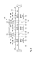
Fig. 1 is a schematic, cross-sectional frontal view of a first example of a sheet feeder according to the invention; -
Fig. 2 is a cross-sectional view along the line II-II inFig. 1 ; -
Fig. 3 is a schematic, cross-sectional frontal view of a second example of a sheet feeder, which does not form part of the present invention; and -
Fig. 4 is a cross-sectional side view of an implementation of a third example of a sheet feeder according to the present invention. - The invention is first described with reference to the example shown in
Figs. 1 and 2 . According to this example, a sheet feeder 1 has asupport 2 defining asupport plane 3 for supporting a stack of sheets 4 (seeFig. 2 ). - The sheet feeder 1 further has circulatable feeding members in the form of
feeding rollers 5 that each have acircumferential feeding surface 6 of which aportion 7 faces in afirst direction 8 transverse to thesupport plane 3 for frictionally engaging asheet 9 from thestack 4. Thefeeding rollers 5 are fixed to ashaft 16 that is rotationally suspended to aframe 15. For driving rotation of theshaft 16 and thefeeding rollers 5, apulley 17 about which adrive belt 18 is tensioned is fixed to theshaft 16. Circulation of thedrive belt 18 can for instance be driven by a motor via a pulley coupled directly or indirectly (for instance via a clutch) to an output shaft of the motor (not shown). - By rotating the
rollers 5 in a feeding sense ofrotation 10, theportions 7 of thecircumferential feeding surfaces 6 that face in thefirst direction 8 are movable in afeeding direction 28 transverse to thefirst direction 8 in the course of the circulation for exerting traction to thesheet 9 frictionally engaged by thefeeding rollers 6. - For separating succeeding
sheets 23 from asheet 9 to be fed, the sheet feeder 1 has a separatingunit 11 with three separatingmembers members separation surface second direction 22 opposite to thefirst direction 8 for frictionally engaging thesheet 9 or an entrained next sheet from thestack 4. The separatingunit 11 is fixedly mounted to theframe 15 of the sheet feeder 1. - In a
lateral direction 27 transverse to thefeeding direction 28 and to the first andsecond directions feeding surfaces 6 are each located between two of theseparation surfaces surfaces 20 is located between twofeeding surfaces 6. - As is best seen in
Fig. 1 , asheet 9 being fed and separated is bent to some extent into a wavy pattern inlateral direction 27. Because the sheet does not pass between a gap between a feeding surface and a separating surface, the separating mechanism is relatively insensitive to a precise adjustment of the positions of the feeding and separatingsurfaces - For supplying sheets from the
stack 4 to thefeeding surface 6 and the separating surfaces 19-21, asupply roller 24 drivable in the feeding sense ofrotation 10 is provided. A portion of the circumference of the supply roller projects upwardly of thesupport plane 3 for frictionally engaging alowermost sheet 9 of thestack 4. Downstream of thefeeding surface 6 and the separating surfaces 19-21,transport rollers rotation 10 are provided. Sensors and a control structure can be provided for controlling rotation of thetransport rollers - The
separating surfaces resilient zone adjacent feeding surface 6. Theresilient zones stiff zones surfaces adjacent feeding surface 6 than the respectiveresilient zone - Because the resilient zones are more resilient than the respective stiff zones of the separating surfaces more remote from the laterally adjacent feeding surface than the resilient zone, the sensitivity of the separating mechanism to differences in the thickness and the stiffness of sheets is reduced. Because the resilience is integrated in the separating member, the construction is simple and can be manufactured at low costs.
- In the present example, the
feeding surfaces 6 are located outside areas opposite theseparating surfaces resilient zones feeding surfaces 6 and theseparating surfaces - The separating
unit 11 is manufactured in the form of an integrally formed piece of (preferably rubber) material, so a plurality of separating members can be manufactured and installed in a simple and low-cost manner. - In the sheet feeder according to the present example, the
resilient zones lateral direction 27 from asupport portion member - For effectively accommodating to differences in thickness and stiffness of the sheets processed it is preferred that, as in the present example, the
resilient zones stiff zones second direction sheet 9 being fed and separated. However, also resilience in lateral direction can contribute significantly to accommodating to differences in thickness and stiffness of the sheets processed. - In the example of a
separator 101 shown inFig. 3 , which does not form part of the present invention, three feedingrollers 105 are provided. Each of these feedingrollers 105 has acircumferential feeding surface 106, which has resilientouter zones 135 and a stiffcentral zone 136. Theouter zones 135 are more resilient than thecentral zones 136 because the outer zones are formed by surface portions of laterally distal portions of flanges laterally projecting from acentral disk portion 138 of therespective feeding roller 105. Since the relatively thin walled flanges can be bent inwardly relatively easily, the laterally distal portions of these flanges are resilient in radially inward direction. According to the present example, thesedisk portions 138 have a thickness which decreases in radially outward direction from a hub via which theroller 105 is mounted to anaxle 116, so thedisk portions 138 are thickest where the loads to which the disk portions are subjected are largest. This keeps the flanges positioned accurately in lateral direction, which does in turn allow the feedingrollers 105 to be mounted with relatively small clearances in lateral direction relative to separatingsurfaces 119 of separatingmembers 111 and relative to openings inguide 102. A similar effect may also be achieved by providing the central portions in thin walled form with support flanges extending radially and projecting laterally. - The separating
members 111 are fixed to the frame 115 from which theaxle 116 is rotatably suspended so that, in lateral direction each separatingmember 111 is located between two directlyadjacent feeding rollers 105. In a direction generally perpendicular to the feeding and separating surfaces, the distance between the feeding surfaces and the separating surfaces, or to a lateral continuation thereof, is preferably smaller than the thickness of the thinnest sheet to be processed, e.g. thinner than 0.06 mm and more preferably the distance between the feeding surfaces and a lateral continuation of the separating surface is zero or it is provided that the feeding rollers project slightly beyond the separating surfaces 119, preferably over a distance smaller than 3 mm and, more preferably, over a distance smaller than 1.5 mm. The relative positions of the feeding and the separating surfaces in a direction generally perpendicular to the feeding and separating surfaces may also be adjustable to be able to separate sheet items of more widely varying thickness and stiffness (the items to be separated in the stack having generally identical thicknesses and stiffnesses), for instance ranging from items of thick plate material to items of flexible plastic material. The separatingmembers 111 each have flanges extending laterally fromsupport portions 133. Like thedisk portions 138 of the feedingrollers 105, the support portions of the separatingmembers 111 each have a thickness that decreases from a base side towards the flanges, so that also the flanges of the support members are maintained accurately positioned in lateral directions, even when subjected to lateral loads, while the flanges project laterally over a sufficiently large distance to allow the free end zones thereof to be deflected away from the feedingrollers 105 in response to loads exerted thereon by paper passing between the feedingrollers 105 and thesupport members 111. The separatingsurface portions 119 of the separating members, which face theaxle 116, have laterallyouter zones 129 that are more resilient than stiffcentral zones 131. - In the separator according to this example resilient
outer zones rollers 105 and the separatingmembers 111. - In the example of an implementation of a
separator 201 according to the invention shown inFig. 4 , thesheets 204 to be separated are supported on edge on aplatform 202. Anend support 239 has rollers 240-242 on opposite sides of the platform for guiding theend support 239 along theplatform 202 towards and away from feedingrollers 205 and a separatingmember 211, while keeping theend support 239 oriented relative to theplatform 202 such that a face of theend support 239 facing thesheets 204 is maintained at a generally fixed oblique angle relative to theplatform 202. - Separating
surfaces 219 of the separatingmember 211 and anoppositely facing segment 207 of thecircumferential surface 206 of the feedingroller 205 are generally in line with anupper surface 203 of theplatform 202, on which surface 203 the edges of thesheets 204 rest. The feedingroller 205 is coupled to a drive 218 (shown schematically only) for driving rotation of the feedingroller 205 in a sense ofrotation 210, such that thesegment 207 of thecircumferential surface 206 of the feedingroller 205 facing in a direction opposite to the separating surfaces 219 and theupper face 203 of theplatform 202 moves generally in afeeding direction 228 along the platform and away from the stack ofsheets 204. - An outer one 223 of the
sheets 204 is in contact with thecircumferential surface 206 of the feedingroller 205, since the stack is urged towards the feedingroller 205 by gravity, which effect is enhanced by the weight of theend support 239. Alternatively, or in addition, the end support may also be urged against the stack by other means, such as a spring, a motor or gravity acting on a weight coupled to the end support via a string or a lever. Since the outer one 223 of thesheets 204 is in contact with thecircumferential surface 206 of the feedingroller 205, the feedingroller 205 also provides for the supply of sheets towards the separating area where the separating surfaces 219 and the oppositely facing segment orsegments 207 of thecircumference 206 of the feedingroller 205 are located. Thus, no separate rollers and drive is necessary for supplying sheets to the separating area. A separator as shown inFig. 4 is particularly suitable for separating relatively stiff sheets, such as business reply cards and envelopes. - Within the framework of the invention as defined by the claims, many other embodiments and variants are conceivable. For instance, instead of a surface on a stationary separating member, the separating surface can be a circumferential surface of a circulatable member such as a roller or a belt. The circulatability of the separation surface may for instance be employed to allow the separation surface to be entrained if only a single sheet item passes between the separation and feeding surfaces. Circulating the separation surface may also be carried out only to bring a fresh portion or fresh portions of separation surface in the operating area near to the feeding surface or surfaces. For that purpose the circulatability in the operatinmg area near the feeding surface or surfaces does not have to be in a direction parallel to the feeding direction of sheet items being separated and fed, but may for instance be perpendicular to that direction.
- Furthermore, the suspension of the separating and/or feeding members may be essentially rigid or resilient, the latter option allowing the mutual positions of the feeding and separating surfaces to accommodate to the processing of sheet items of widely varying stiffness and/or thickness.
- If, as described, the relative positions of the feeding and separating surfaces are adjustable laterally and/or in directions generally perpendicular to the feeding and separating surfaces, for automatic adjustment the feeder may be equipped with one or more sensors for measuring flexural deformation of a sheet item between the feeding and separating surfaces and a controller connected to the sensor or sensors for receiving a signal representing the measured flexural deformation. If the controller is then arranged for adjusting the relative positions of the feeding and separating surfaces in response and in accordance with the signal representing the measured flexural deformation, the adjustment of the relative positions of the feeding and separating surfaces can be carried out automatically, without resorting to measuring the thickness and or stiffness of the sheet items to be separated. The sensors may for instance be hall sensors or optical sensors as described in
European patent application 2 085 743 .
Claims (5)
- A sheet item feeder comprising:at least three surfaces consisting of:- at least one circulatable feeding surface (6; 106; 206) of which at least a portion (7; 207) faces in a first direction (8) transverse to a support plane (3; 203) for frictionally engaging a sheet item (23; 223) from a stack (4; 204) and is movable in a feeding direction (28; 228) transverse to said first direction (8) in the course of the circulation for exerting traction to that sheet item (23; 223); and- at least one separation surface (19, 20; 119; 219) of which at least a portion faces in a second direction (22) opposite to the first direction for frictionally engaging the sheet item (23; 223) or an entrained next sheet item from the stack (4; 204);- wherein, in a lateral direction transverse to the feeding direction (28; 228) and to the first and second directions (8, 22), at least the at least one feeding surface (6; 106) is located between two of the separation surfaces (19; 119) or the at least one separating surface (20; 119) is located between two of the feeding surfaces (6; 106) for engaging the sheet item (23; 223) and the entrained next sheet item between the feeding surface (6; 106; 206) and the separating surface (19, 20; 119; 219) in laterally staggered positions;
characterized in that,- at least the separating surface (19, 20; 119) has a resilient zone (29, 30; 129, 135) laterally adjacent to the feeding surface or at least one of the feeding surfaces (6; 106), the resilient zone (29, 30; 129, 135) being more resilient than a stiff zone (31, 32; 131, 136) of the separating surface (19; 119) more remote from the laterally adjacent feeding surface or surfaces (6; 106) than the resilient zone (29, 30; 129, 135). - A feeder according to claim 1, wherein the at least one feeding surface (6; 106) is located laterally outside areas directly opposite the at least one separating surface (19, 20; 119) only.
- A feeder according to claim 1 or 2, wherein the resilient zone (29, 30; 129, 135) is part of a flange projecting in a lateral direction from a support portion (33; 138) of the separating member (11; 111).
- A feeder according to any one of the preceding claims, wherein the resilient zone (29, 30; 129, 135) is more resilient than the stiff zone (31, 32; 131, 136) in the first or second direction (8; 22).
- A feeder according to any one of the preceding claims, wherein relative positions of the feeding and separating surfaces are adjustable, the feeder further comprising at least one sensor arranged for measuring flexural deformation of a sheet item between the feeding and separating surfaces and a controller connected to the at least one sensor for receiving a signal representing the measured flexural deformation, the controller being arranged for adjusting the relative positions of the feeding and separating surfaces in response and in accordance with the signal representing the measured flexural deformation.
Priority Applications (2)
| Application Number | Priority Date | Filing Date | Title |
|---|---|---|---|
| EP10197473.1A EP2471729B1 (en) | 2010-12-31 | 2010-12-31 | Sheet item feeder |
| US13/341,356 US8517372B2 (en) | 2010-12-31 | 2011-12-30 | Sheet item feeder |
Applications Claiming Priority (1)
| Application Number | Priority Date | Filing Date | Title |
|---|---|---|---|
| EP10197473.1A EP2471729B1 (en) | 2010-12-31 | 2010-12-31 | Sheet item feeder |
Publications (2)
| Publication Number | Publication Date |
|---|---|
| EP2471729A1 EP2471729A1 (en) | 2012-07-04 |
| EP2471729B1 true EP2471729B1 (en) | 2015-06-03 |
Family
ID=44012562
Family Applications (1)
| Application Number | Title | Priority Date | Filing Date |
|---|---|---|---|
| EP10197473.1A Not-in-force EP2471729B1 (en) | 2010-12-31 | 2010-12-31 | Sheet item feeder |
Country Status (2)
| Country | Link |
|---|---|
| US (1) | US8517372B2 (en) |
| EP (1) | EP2471729B1 (en) |
Family Cites Families (17)
| Publication number | Priority date | Publication date | Assignee | Title |
|---|---|---|---|---|
| US1955066A (en) | 1933-01-18 | 1934-04-17 | Nat Postal Meter Company | Stripper and feeder for postal machines |
| US2635874A (en) | 1950-09-22 | 1953-04-21 | Pitney Bowes Inc | Letter feed and separator device |
| US4666141A (en) * | 1984-10-01 | 1987-05-19 | Labombarde Raymond A | Apparatus and method for reverse roll feed of shingled blanks |
| JPS62215436A (en) | 1986-03-17 | 1987-09-22 | Nippon Seimitsu Kogyo Kk | Sheet carrying apparatus |
| JP2655916B2 (en) * | 1989-07-25 | 1997-09-24 | 三田工業株式会社 | Paper feed mechanism |
| US5145161A (en) * | 1990-05-03 | 1992-09-08 | Bell & Howell Phillipsburg Co. | Sheet feeder |
| US5265868A (en) * | 1990-05-03 | 1993-11-30 | Bell & Howell Phillipsburg | Sheet feeder |
| US5203846A (en) * | 1991-11-12 | 1993-04-20 | A. B. Dick Company | Media feed roll apparatus and method for its use |
| DE10105521A1 (en) * | 2001-02-07 | 2002-08-08 | Giesecke & Devrient Gmbh | Device and method for separating sheet material |
| GB2380185B (en) | 2001-09-28 | 2005-01-12 | Pitney Bowes Ltd | Apparatus and method for folding a sheet |
| US7419154B2 (en) | 2004-05-03 | 2008-09-02 | Zih Corporation | Feeder device having adjustably flexible gate apparatus and associated method |
| US7624978B2 (en) | 2005-03-16 | 2009-12-01 | Kaiping James C | Sheet feeder with feed belts that move toward an away from each other |
| US7748696B2 (en) | 2005-03-16 | 2010-07-06 | Kaiping James C | Sheet feeder with feed belts and traction belt |
| US7722028B2 (en) | 2005-08-02 | 2010-05-25 | Bitner Robert J | Feeder separation technology |
| JP2007126247A (en) * | 2005-11-02 | 2007-05-24 | Toshiba Corp | Rubber roller, and paper sheet extraction device incorporating the same |
| US7726643B2 (en) | 2006-12-28 | 2010-06-01 | Pitney Bowes Inc. | Paper feeder having hard nip and flexible nip |
| EP2085743B1 (en) | 2008-01-31 | 2011-03-02 | Neopost Technologies | Thickness sensor for measuring the thickness of sheet-like objects |
-
2010
- 2010-12-31 EP EP10197473.1A patent/EP2471729B1/en not_active Not-in-force
-
2011
- 2011-12-30 US US13/341,356 patent/US8517372B2/en active Active
Also Published As
| Publication number | Publication date |
|---|---|
| EP2471729A1 (en) | 2012-07-04 |
| US20120175839A1 (en) | 2012-07-12 |
| US8517372B2 (en) | 2013-08-27 |
Similar Documents
| Publication | Publication Date | Title |
|---|---|---|
| EP2301869B1 (en) | Paper sheet pick up device | |
| JP2006193286A (en) | Sheet feeding device and jamming detection method for the device | |
| US7419155B2 (en) | Device for separating sheet-type products | |
| CA2740839C (en) | Envelope conveying and positioning apparatus and related methods | |
| CA2739585C (en) | Inserting apparatus for discrete objects into envelopes and related methods | |
| US8825204B2 (en) | Method and control circuit for adjusting a gap | |
| JP4033844B2 (en) | Paper sheet feeding device | |
| JPH0558512A (en) | Paper sheet feed-delivery device | |
| EP2045200B1 (en) | Ingestion assembly for augmenting sheet material separation in a singulating apparatus | |
| US4204667A (en) | Semi-circular stack sheet feeding apparatus | |
| CA1059541A (en) | Floating gate sheet separator | |
| EP2471729B1 (en) | Sheet item feeder | |
| JP4752583B2 (en) | Paper sheet separation and accumulation mechanism | |
| JP2680981B2 (en) | Paper transport device | |
| JP4862352B2 (en) | Recording medium discharge apparatus and image forming apparatus | |
| JPH06144617A (en) | Paper feeding device | |
| EP2428475B1 (en) | System for controlling a singulating belt in a mailpiece feeder | |
| GB2462262A (en) | Adjustable vacuum sheet feeder with adjustable sheet retaining device | |
| US7862040B2 (en) | Item feeder with overthickness detection | |
| JP6664922B2 (en) | Sheet separation device | |
| US7059595B2 (en) | Method and apparatus for controlling feeding of sheets | |
| JPH03162331A (en) | Paper feed device | |
| JPH0638029Y2 (en) | Overlap detection device in paper processing machine | |
| JPH0126669Y2 (en) | ||
| JPH05266316A (en) | Detection device for double sending of card and the like |
Legal Events
| Date | Code | Title | Description |
|---|---|---|---|
| AK | Designated contracting states |
Kind code of ref document: A1 Designated state(s): AL AT BE BG CH CY CZ DE DK EE ES FI FR GB GR HR HU IE IS IT LI LT LU LV MC MK MT NL NO PL PT RO RS SE SI SK SM TR |
|
| AX | Request for extension of the european patent |
Extension state: BA ME |
|
| PUAI | Public reference made under article 153(3) epc to a published international application that has entered the european phase |
Free format text: ORIGINAL CODE: 0009012 |
|
| 17P | Request for examination filed |
Effective date: 20120924 |
|
| 17Q | First examination report despatched |
Effective date: 20140212 |
|
| GRAP | Despatch of communication of intention to grant a patent |
Free format text: ORIGINAL CODE: EPIDOSNIGR1 |
|
| INTG | Intention to grant announced |
Effective date: 20141119 |
|
| GRAS | Grant fee paid |
Free format text: ORIGINAL CODE: EPIDOSNIGR3 |
|
| GRAP | Despatch of communication of intention to grant a patent |
Free format text: ORIGINAL CODE: EPIDOSNIGR1 |
|
| INTG | Intention to grant announced |
Effective date: 20150320 |
|
| GRAA | (expected) grant |
Free format text: ORIGINAL CODE: 0009210 |
|
| AK | Designated contracting states |
Kind code of ref document: B1 Designated state(s): AL AT BE BG CH CY CZ DE DK EE ES FI FR GB GR HR HU IE IS IT LI LT LU LV MC MK MT NL NO PL PT RO RS SE SI SK SM TR |
|
| REG | Reference to a national code |
Ref country code: GB Ref legal event code: FG4D |
|
| REG | Reference to a national code |
Ref country code: CH Ref legal event code: EP |
|
| REG | Reference to a national code |
Ref country code: AT Ref legal event code: REF Ref document number: 729791 Country of ref document: AT Kind code of ref document: T Effective date: 20150715 Ref country code: IE Ref legal event code: FG4D |
|
| REG | Reference to a national code |
Ref country code: DE Ref legal event code: R096 Ref document number: 602010025020 Country of ref document: DE |
|
| REG | Reference to a national code |
Ref country code: AT Ref legal event code: MK05 Ref document number: 729791 Country of ref document: AT Kind code of ref document: T Effective date: 20150603 |
|
| PG25 | Lapsed in a contracting state [announced via postgrant information from national office to epo] |
Ref country code: HR Free format text: LAPSE BECAUSE OF FAILURE TO SUBMIT A TRANSLATION OF THE DESCRIPTION OR TO PAY THE FEE WITHIN THE PRESCRIBED TIME-LIMIT Effective date: 20150603 Ref country code: ES Free format text: LAPSE BECAUSE OF FAILURE TO SUBMIT A TRANSLATION OF THE DESCRIPTION OR TO PAY THE FEE WITHIN THE PRESCRIBED TIME-LIMIT Effective date: 20150603 Ref country code: NO Free format text: LAPSE BECAUSE OF FAILURE TO SUBMIT A TRANSLATION OF THE DESCRIPTION OR TO PAY THE FEE WITHIN THE PRESCRIBED TIME-LIMIT Effective date: 20150903 Ref country code: FI Free format text: LAPSE BECAUSE OF FAILURE TO SUBMIT A TRANSLATION OF THE DESCRIPTION OR TO PAY THE FEE WITHIN THE PRESCRIBED TIME-LIMIT Effective date: 20150603 Ref country code: LT Free format text: LAPSE BECAUSE OF FAILURE TO SUBMIT A TRANSLATION OF THE DESCRIPTION OR TO PAY THE FEE WITHIN THE PRESCRIBED TIME-LIMIT Effective date: 20150603 |
|
| REG | Reference to a national code |
Ref country code: NL Ref legal event code: MP Effective date: 20150603 |
|
| REG | Reference to a national code |
Ref country code: LT Ref legal event code: MG4D |
|
| PG25 | Lapsed in a contracting state [announced via postgrant information from national office to epo] |
Ref country code: GR Free format text: LAPSE BECAUSE OF FAILURE TO SUBMIT A TRANSLATION OF THE DESCRIPTION OR TO PAY THE FEE WITHIN THE PRESCRIBED TIME-LIMIT Effective date: 20150904 Ref country code: AT Free format text: LAPSE BECAUSE OF FAILURE TO SUBMIT A TRANSLATION OF THE DESCRIPTION OR TO PAY THE FEE WITHIN THE PRESCRIBED TIME-LIMIT Effective date: 20150603 Ref country code: LV Free format text: LAPSE BECAUSE OF FAILURE TO SUBMIT A TRANSLATION OF THE DESCRIPTION OR TO PAY THE FEE WITHIN THE PRESCRIBED TIME-LIMIT Effective date: 20150603 Ref country code: RS Free format text: LAPSE BECAUSE OF FAILURE TO SUBMIT A TRANSLATION OF THE DESCRIPTION OR TO PAY THE FEE WITHIN THE PRESCRIBED TIME-LIMIT Effective date: 20150603 Ref country code: BG Free format text: LAPSE BECAUSE OF FAILURE TO SUBMIT A TRANSLATION OF THE DESCRIPTION OR TO PAY THE FEE WITHIN THE PRESCRIBED TIME-LIMIT Effective date: 20150903 |
|
| REG | Reference to a national code |
Ref country code: FR Ref legal event code: PLFP Year of fee payment: 6 |
|
| PG25 | Lapsed in a contracting state [announced via postgrant information from national office to epo] |
Ref country code: EE Free format text: LAPSE BECAUSE OF FAILURE TO SUBMIT A TRANSLATION OF THE DESCRIPTION OR TO PAY THE FEE WITHIN THE PRESCRIBED TIME-LIMIT Effective date: 20150603 |
|
| PG25 | Lapsed in a contracting state [announced via postgrant information from national office to epo] |
Ref country code: PL Free format text: LAPSE BECAUSE OF FAILURE TO SUBMIT A TRANSLATION OF THE DESCRIPTION OR TO PAY THE FEE WITHIN THE PRESCRIBED TIME-LIMIT Effective date: 20150603 Ref country code: PT Free format text: LAPSE BECAUSE OF FAILURE TO SUBMIT A TRANSLATION OF THE DESCRIPTION OR TO PAY THE FEE WITHIN THE PRESCRIBED TIME-LIMIT Effective date: 20151006 Ref country code: RO Free format text: LAPSE BECAUSE OF NON-PAYMENT OF DUE FEES Effective date: 20150603 Ref country code: SK Free format text: LAPSE BECAUSE OF FAILURE TO SUBMIT A TRANSLATION OF THE DESCRIPTION OR TO PAY THE FEE WITHIN THE PRESCRIBED TIME-LIMIT Effective date: 20150603 Ref country code: IS Free format text: LAPSE BECAUSE OF FAILURE TO SUBMIT A TRANSLATION OF THE DESCRIPTION OR TO PAY THE FEE WITHIN THE PRESCRIBED TIME-LIMIT Effective date: 20151003 Ref country code: CZ Free format text: LAPSE BECAUSE OF FAILURE TO SUBMIT A TRANSLATION OF THE DESCRIPTION OR TO PAY THE FEE WITHIN THE PRESCRIBED TIME-LIMIT Effective date: 20150603 |
|
| REG | Reference to a national code |
Ref country code: DE Ref legal event code: R097 Ref document number: 602010025020 Country of ref document: DE |
|
| PLBE | No opposition filed within time limit |
Free format text: ORIGINAL CODE: 0009261 |
|
| STAA | Information on the status of an ep patent application or granted ep patent |
Free format text: STATUS: NO OPPOSITION FILED WITHIN TIME LIMIT |
|
| PG25 | Lapsed in a contracting state [announced via postgrant information from national office to epo] |
Ref country code: IT Free format text: LAPSE BECAUSE OF FAILURE TO SUBMIT A TRANSLATION OF THE DESCRIPTION OR TO PAY THE FEE WITHIN THE PRESCRIBED TIME-LIMIT Effective date: 20150603 Ref country code: DK Free format text: LAPSE BECAUSE OF FAILURE TO SUBMIT A TRANSLATION OF THE DESCRIPTION OR TO PAY THE FEE WITHIN THE PRESCRIBED TIME-LIMIT Effective date: 20150603 |
|
| 26N | No opposition filed |
Effective date: 20160304 |
|
| PG25 | Lapsed in a contracting state [announced via postgrant information from national office to epo] |
Ref country code: SI Free format text: LAPSE BECAUSE OF FAILURE TO SUBMIT A TRANSLATION OF THE DESCRIPTION OR TO PAY THE FEE WITHIN THE PRESCRIBED TIME-LIMIT Effective date: 20150603 Ref country code: BE Free format text: LAPSE BECAUSE OF NON-PAYMENT OF DUE FEES Effective date: 20151231 |
|
| PG25 | Lapsed in a contracting state [announced via postgrant information from national office to epo] |
Ref country code: LU Free format text: LAPSE BECAUSE OF FAILURE TO SUBMIT A TRANSLATION OF THE DESCRIPTION OR TO PAY THE FEE WITHIN THE PRESCRIBED TIME-LIMIT Effective date: 20151231 Ref country code: MC Free format text: LAPSE BECAUSE OF FAILURE TO SUBMIT A TRANSLATION OF THE DESCRIPTION OR TO PAY THE FEE WITHIN THE PRESCRIBED TIME-LIMIT Effective date: 20150603 |
|
| REG | Reference to a national code |
Ref country code: CH Ref legal event code: PL |
|
| REG | Reference to a national code |
Ref country code: IE Ref legal event code: MM4A |
|
| PG25 | Lapsed in a contracting state [announced via postgrant information from national office to epo] |
Ref country code: IE Free format text: LAPSE BECAUSE OF NON-PAYMENT OF DUE FEES Effective date: 20151231 Ref country code: CH Free format text: LAPSE BECAUSE OF NON-PAYMENT OF DUE FEES Effective date: 20151231 Ref country code: LI Free format text: LAPSE BECAUSE OF NON-PAYMENT OF DUE FEES Effective date: 20151231 |
|
| REG | Reference to a national code |
Ref country code: FR Ref legal event code: PLFP Year of fee payment: 7 |
|
| PG25 | Lapsed in a contracting state [announced via postgrant information from national office to epo] |
Ref country code: BE Free format text: LAPSE BECAUSE OF FAILURE TO SUBMIT A TRANSLATION OF THE DESCRIPTION OR TO PAY THE FEE WITHIN THE PRESCRIBED TIME-LIMIT Effective date: 20150603 |
|
| PG25 | Lapsed in a contracting state [announced via postgrant information from national office to epo] |
Ref country code: SM Free format text: LAPSE BECAUSE OF FAILURE TO SUBMIT A TRANSLATION OF THE DESCRIPTION OR TO PAY THE FEE WITHIN THE PRESCRIBED TIME-LIMIT Effective date: 20150603 Ref country code: HU Free format text: LAPSE BECAUSE OF FAILURE TO SUBMIT A TRANSLATION OF THE DESCRIPTION OR TO PAY THE FEE WITHIN THE PRESCRIBED TIME-LIMIT; INVALID AB INITIO Effective date: 20101231 |
|
| PG25 | Lapsed in a contracting state [announced via postgrant information from national office to epo] |
Ref country code: CY Free format text: LAPSE BECAUSE OF FAILURE TO SUBMIT A TRANSLATION OF THE DESCRIPTION OR TO PAY THE FEE WITHIN THE PRESCRIBED TIME-LIMIT Effective date: 20150603 Ref country code: SE Free format text: LAPSE BECAUSE OF FAILURE TO SUBMIT A TRANSLATION OF THE DESCRIPTION OR TO PAY THE FEE WITHIN THE PRESCRIBED TIME-LIMIT Effective date: 20150603 Ref country code: NL Free format text: LAPSE BECAUSE OF FAILURE TO SUBMIT A TRANSLATION OF THE DESCRIPTION OR TO PAY THE FEE WITHIN THE PRESCRIBED TIME-LIMIT Effective date: 20150603 |
|
| PG25 | Lapsed in a contracting state [announced via postgrant information from national office to epo] |
Ref country code: TR Free format text: LAPSE BECAUSE OF FAILURE TO SUBMIT A TRANSLATION OF THE DESCRIPTION OR TO PAY THE FEE WITHIN THE PRESCRIBED TIME-LIMIT Effective date: 20150603 Ref country code: MT Free format text: LAPSE BECAUSE OF FAILURE TO SUBMIT A TRANSLATION OF THE DESCRIPTION OR TO PAY THE FEE WITHIN THE PRESCRIBED TIME-LIMIT Effective date: 20150603 |
|
| REG | Reference to a national code |
Ref country code: FR Ref legal event code: PLFP Year of fee payment: 8 |
|
| PG25 | Lapsed in a contracting state [announced via postgrant information from national office to epo] |
Ref country code: MK Free format text: LAPSE BECAUSE OF FAILURE TO SUBMIT A TRANSLATION OF THE DESCRIPTION OR TO PAY THE FEE WITHIN THE PRESCRIBED TIME-LIMIT Effective date: 20150603 |
|
| PG25 | Lapsed in a contracting state [announced via postgrant information from national office to epo] |
Ref country code: AL Free format text: LAPSE BECAUSE OF FAILURE TO SUBMIT A TRANSLATION OF THE DESCRIPTION OR TO PAY THE FEE WITHIN THE PRESCRIBED TIME-LIMIT Effective date: 20150603 |
|
| REG | Reference to a national code |
Ref country code: DE Ref legal event code: R082 Ref document number: 602010025020 Country of ref document: DE Representative=s name: CBDL PATENTANWAELTE, DE Ref country code: DE Ref legal event code: R081 Ref document number: 602010025020 Country of ref document: DE Owner name: QUADIENT TECHNOLOGIES FRANCE, FR Free format text: FORMER OWNER: NEOPOST TECHNOLOGIES, BAGNEUX, FR |
|
| PGFP | Annual fee paid to national office [announced via postgrant information from national office to epo] |
Ref country code: DE Payment date: 20211210 Year of fee payment: 12 Ref country code: GB Payment date: 20211222 Year of fee payment: 12 Ref country code: FR Payment date: 20211224 Year of fee payment: 12 |
|
| REG | Reference to a national code |
Ref country code: DE Ref legal event code: R082 Ref document number: 602010025020 Country of ref document: DE Representative=s name: CBDL PATENTANWAELTE GBR, DE |
|
| REG | Reference to a national code |
Ref country code: DE Ref legal event code: R119 Ref document number: 602010025020 Country of ref document: DE |
|
| GBPC | Gb: european patent ceased through non-payment of renewal fee |
Effective date: 20221231 |
|
| PG25 | Lapsed in a contracting state [announced via postgrant information from national office to epo] |
Ref country code: GB Free format text: LAPSE BECAUSE OF NON-PAYMENT OF DUE FEES Effective date: 20221231 Ref country code: DE Free format text: LAPSE BECAUSE OF NON-PAYMENT OF DUE FEES Effective date: 20230701 |
|
| PG25 | Lapsed in a contracting state [announced via postgrant information from national office to epo] |
Ref country code: FR Free format text: LAPSE BECAUSE OF NON-PAYMENT OF DUE FEES Effective date: 20221231 |