EP0454023A2 - Circular knitting machine with casting-off sinker actuation device - Google Patents
Circular knitting machine with casting-off sinker actuation device Download PDFInfo
- Publication number
- EP0454023A2 EP0454023A2 EP91106433A EP91106433A EP0454023A2 EP 0454023 A2 EP0454023 A2 EP 0454023A2 EP 91106433 A EP91106433 A EP 91106433A EP 91106433 A EP91106433 A EP 91106433A EP 0454023 A2 EP0454023 A2 EP 0454023A2
- Authority
- EP
- European Patent Office
- Prior art keywords
- needle cylinder
- respect
- actuation element
- sinker ring
- countercam
- Prior art date
- Legal status (The legal status is an assumption and is not a legal conclusion. Google has not performed a legal analysis and makes no representation as to the accuracy of the status listed.)
- Withdrawn
Links
Images


Classifications
-
- D—TEXTILES; PAPER
- D04—BRAIDING; LACE-MAKING; KNITTING; TRIMMINGS; NON-WOVEN FABRICS
- D04B—KNITTING
- D04B15/00—Details of, or auxiliary devices incorporated in, weft knitting machines, restricted to machines of this kind
- D04B15/32—Cam systems or assemblies for operating knitting instruments
- D04B15/34—Cam systems or assemblies for operating knitting instruments for dials
-
- D—TEXTILES; PAPER
- D04—BRAIDING; LACE-MAKING; KNITTING; TRIMMINGS; NON-WOVEN FABRICS
- D04B—KNITTING
- D04B9/00—Circular knitting machines with independently-movable needles
- D04B9/42—Circular knitting machines with independently-movable needles specially adapted for producing goods of particular configuration
- D04B9/46—Circular knitting machines with independently-movable needles specially adapted for producing goods of particular configuration stockings, or portions thereof
Definitions
- the present invention relates to a circular knitting machine, particularly of the type for manufacturing socks and stockings, with a casting-off sinker actuation device.
- some types of knitting machines in particular circular single-cylinder machines for manufacturing socks and stockings, have casting-off sinkers which are arranged in radial grooves of a plate-like support which is rigidly associated with the needle cylinder proximate to its upper end.
- the casting-off sinkers are offset with respect to the needles, so that each sinker is arranged between two adjacent needles, and are actuated, during the rotation of the needle cylinder about its own axis, with a reciprocating motion along a direction which is radial with respect to the needle cylinder.
- the sinkers are moved away from the axis of the needle cylinder when the needles, after taking hold of the thread, begin their descent so as to facilitate the forming of new loops which rest on the upper portion of the sinkers, which is usually planar and is termed "casting-off plane", whereas the previously formed loops are cast off.
- the sinkers are moved toward the axis of the needle cylinder so as to engage the new loops with a beak which is arranged above the casting-off plane, so as to tense and retain the loops against the stem of the needles.
- the movement of the casting-off sinkers in a radial direction with respect to the needle cylinder is obtained by means of an inner annular cam and at least one outer countercam which are associated with a sinker ring which is arranged above the plate-like support.
- the annular cam and the countercam extend around the needle cylinder and define a path with portions which move toward the needle cylinder axis and portions which move away therefrom; this path is followed by a sinker heel, which protrudes upward from the plate-like support, when the needle cylinder is actuated with a rotary motion about its own axis.
- the countercam or countercams can yield outward in contrast with return springs.
- the springs keep the countercam in the position which is closest to the inner cam, achieving a closer approach of the sinkers to the needle cylinder axis, whereas with short loops and/or with scarcely elastic threads the resistance of the knitting causes the yielding of the springs and therefore a partial outward movement of the countercam, thus avoiding an excessive approach of the sinkers to the needle cylinder axis.
- the springs employed can in fact be excessively rigid or excessively yielding with respect to the results to be obtained.
- the centrifugal force which acts on the sinkers causes the yielding of the springs and therefore an outward spacing of the countercam or countercams, with the consequence of significantly reducing or completely eliminating the return of the sinkers toward the needle cylinder axis.
- the aim of the present invention is to solve the problems described above by providing a circular knitting machine, particularly of the type for manufacturing socks and stockings, with a casting-off sinker actuation device which allows to vary the tension exerted by the sinkers on the loops of knitting according to the thread being used and according to the knitting conditions.
- an object of the invention is to provide a machine with a sinker actuation device which ensures the adequate tensing of the knitting being formed even with high needle cylinder rotation rates.
- Another object of the invention is to provide a machine wherein the tensing performed by the sinkers can be varied without requiring interventions for disassembling or replacing machine parts.
- a further object of the invention is to provide a sinker actuation device which is simple to manufacture.
- a circular knitting machine particularly of the type for manufacturing socks and stockings
- a casting-off sinker actuation device which comprises a sinker ring arranged coaxially to the needle cylinder proximate to its upper end and supports at least one cam and at least one countercam, said countercam being arranged outside said cam with respect to the needle cylinder axis, said cam and said countercam defining at least one portion of a path which extends around the needle cylinder axis for a heel of the casting-off sinkers, which are supported by the needle cylinder which can rotate about its axis with respect to said sinker ring, characterized in that it comprises positioning means which are associated with said sinker ring and which can be controllably actuated in order to adjust the position of said countercam along a direction having a radial component with respect to the needle cylinder.
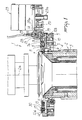
- the machine according to the invention comprises, like known machines, a needle cylinder 2 with an axis 2a which is arranged vertically and with a skirt in which a plurality of axial grooves 3, each accommodating a needle 4, is defined.
- a plate-like support 5 is arranged proximate to the upper end of the needle cylinder 2 and is rigidly associated coaxially to the needle cylinder 2.
- a plurality of radial grooves 6 is defined in the plate-like support 5, and each groove accommodates a casting-off sinker 7 which can be actuated with a reciprocating motion along the related radial groove 6.
- the radial grooves 6 are offset with respect to the axial grooves 3 of the needle cylinder so that each sinker 7 is arranged between two adjacent needles.
- Each sinker 7 has a heel 7a which protrudes upward from the related radial groove, and a sinker ring 8 is mounted above the plate-like support 5.
- an outer ring 9 is arranged around the plate-like support 5 and is associated therewith by interposing a bearing 10, so that the needle cylinder 2, together with the plate-like support 5, can rotate, by means of appropriate rotation means, about the axis 2a with respect to the outer ring 9.
- the sinker ring 8 is fixed to the outer ring 9 and is arranged coaxially to the needle cylinder 2.
- the lower face of the sinker ring 8 is provided with a cam 11, which is fixed to the sinker ring and extends around the needle cylinder, and with four countercams 12a, 12b, 12c, 12d, which face the side of the cam 11 which is directed outward with respect to the needle cylinder, so that a path 13, in which the heels 7a of the sinkers engage, is defined between the cam 11 and the countercams.
- the path 13 extends around the needle cylinder and is shaped substantially in a known manner with portions which move toward the needle cylinder axis 2a and portions which move away therefrom in order to obtain a reciprocating motion of the sinkers 7 along radial directions with respect to the needle cylinder when said needle cylinder is actuated with a rotary motion about its axis 2a with respect to the sinker ring.
- positioning means are provided and can be controllably actuated in order to adjust the countercams along a direction which has a radial component with respect to the needle cylinder.
- Said positioning means comprise an actuation element 14 which is shaped substantially like an annulus and is arranged coaxially to the needle cylinder on the upper face of the sinker ring 8.
- the actuation element 14 is arranged coaxially to the needle cylinder and is partially accommodated, so that it can rotate about the axis 2a, in an annulus-shaped seat 15 defined on the upper face of the sinker ring 8.
- Slots 16 are defined in the actuation element 14 and are circumferentially spaced from one another; a pin 17 is slidingly engaged in each of said slots, passes through an opening 18 of the sinker ring and is rigidly fixed to one of the countercams. More particularly, each of the countercams is fixed to two pins 17, each of which can slide within a slot 18 and is rigidly associated with the actuation element 14 by means of a screw 30.
- Each slot 16 has an eccentric extension with respect to the axis 2a, and each opening 18 is elongated along a direction which is substantially radial with respect to the needle cylinder, so that a partial rotation of the actuation element about the axis 2a with respect to the sinker ring causes a movement of the countercams toward or away from the axis 2a.
- the actuation element 14 has a toothed perimetric portion 19 which is coupled, by means of gearwheels 20, 21, 22, to the output shaft 23a of a step motor 23 which is connected to a programmable electronic control unit 25 which supervises the operation of the machine.
- the gearwheel 20 meshes with the perimetric portion 19 and is rigidly associated, in its rotation about its axis 20a, with the gearwheel 21, which is coaxial thereto and in turn meshes with the gearwheel 22 which is keyed on the output shaft 23a of the step motor 23.
- a radial recess 27 is similarly defined in a portion of the actuation element 14 and, by means of a partial rotation of said actuation element 14 about the axis 2a with respect to the sinker ring 8, can be aligned with the recess 26 so as to allow the manual extraction of a sinker 7 arranged at said recesses in order to replace it if necessary.
- the slot 16 which is closest to the recess 27 and within which a pin, which is fixed to the countercam 12a extending on the recess 26, engages, has an end portion 16a which moves more markedly away, with respect to the remaining part, from the axis 2a and is followed by the related pin during the alignment of the recesses 26 and 27 so that the related countercam is moved out of the area occupied by the recesses 26 and 27 in order to facilitate the extraction of the underlying sinker; the opening 18 related to said pin also has an adequate length in a radial direction in order to allow the movement of the related countercam.
- Safety means are conveniently provided, which detect the position of the actuation element 14 along its arc of a partial rotation, and which are connected to the electronic control unit 25 in order to cause an interruption of the operation of the machine when the recesses 26 and 27 are aligned, in order to avoid damage to the sinkers.
- Said safety means are conveniently constituted by a proximity sensor 28 which is associated with the supporting structure of the step motor 23 and faces a side of the gearwheel 21.
- a depressed or raised portion 29, in the shape of a circular sector, is provided on said face of the gearwheel 21 and is arranged and sized so that it faces the proximity sensor 28 while the actuation element defines the arc of rotation which corresponds to the alignment of the recesses 26 and 27.
- the electronic control unit 25 acts on the step motor 23 in order to obtain a partial rotation of the actuation element 14 about the axis 2 until the pins 17 are moved at an end of the related slot 16, more specifically at the end opposite to the portion 16a of the slot provided with said portion 16a.
- the step motor 23 is reset, eliminating the remaining steps (figure 4).
- the electronic control unit 25 intervenes, following a preset program, on the step motor 23, which in turn causes the partial rotation of the actuation element 14 in order to vary the distance of the countercams 12a, 12b, 12c, 12d from the axis 2a (figures 5 and 6).
- a variation in the distance of the countercams from the axis 2a leads to a variation in the stroke of the casting-off sinkers in their approach toward the axis 2a.
- the action of the sinkers on the loops of knitting can be adjusted with extreme precision according to the thread used and to the tightness of the knitting being formed.
- the electronic control unit 25 When it is necessary to replace one or more casting-off sinkers, the electronic control unit 25, following a specific program, slowly rotates the needle cylinder 2 until the sinker to be replaced is moved at the recess 26, and subsequently rotates the actuation element by means of the step motor 23 until the recess 27 is aligned with the recess 26 (figure 7).
- control unit 25 automatically halts the machine as a consequence of the sensing performed by the proximity sensor 28 in order to avoid accidental releases of the sinkers from the groove in which they are accommodated.
- Another advantage of the casting-off sinker actuation device according to the invention is that it allows rapid maintenance interventions for replacing damaged casting-off sinkers.
- the materials employed, as well as the dimensions, may be any according to the requirements and to the state of the art.
Abstract
Description
- The present invention relates to a circular knitting machine, particularly of the type for manufacturing socks and stockings, with a casting-off sinker actuation device.
- As known, some types of knitting machines, in particular circular single-cylinder machines for manufacturing socks and stockings, have casting-off sinkers which are arranged in radial grooves of a plate-like support which is rigidly associated with the needle cylinder proximate to its upper end.
- The casting-off sinkers are offset with respect to the needles, so that each sinker is arranged between two adjacent needles, and are actuated, during the rotation of the needle cylinder about its own axis, with a reciprocating motion along a direction which is radial with respect to the needle cylinder.
- More particularly, the sinkers are moved away from the axis of the needle cylinder when the needles, after taking hold of the thread, begin their descent so as to facilitate the forming of new loops which rest on the upper portion of the sinkers, which is usually planar and is termed "casting-off plane", whereas the previously formed loops are cast off. After casting off the old loops, while the needles begin a new ascent, the sinkers are moved toward the axis of the needle cylinder so as to engage the new loops with a beak which is arranged above the casting-off plane, so as to tense and retain the loops against the stem of the needles.
- The movement of the casting-off sinkers in a radial direction with respect to the needle cylinder is obtained by means of an inner annular cam and at least one outer countercam which are associated with a sinker ring which is arranged above the plate-like support. The annular cam and the countercam extend around the needle cylinder and define a path with portions which move toward the needle cylinder axis and portions which move away therefrom; this path is followed by a sinker heel, which protrudes upward from the plate-like support, when the needle cylinder is actuated with a rotary motion about its own axis.
- In sock and stocking manufacture, the need to be able to vary the stroke of the sinkers according to the density of the knitting and to the elasticity of the thread is particularly felt.
- In loose knitting, i.e. knitting with long loops, and/or with highly elastic threads, it is in fact convenient for the sinkers to be able to approach more closely the needle cylinder axis, in order to adequately tense the loops being formed, with respect to tight knitting, i.e. knitting with short loops, and/or with scarcely elastic threads for which an excessive advancement of the sinkers toward the needle cylinder axis would cause damage and breakage of the loops.
- In order to satisfy this requirement, in some types of machines the countercam or countercams can yield outward in contrast with return springs. In this manner, with highly elastic threads and/or with long loops, the springs keep the countercam in the position which is closest to the inner cam, achieving a closer approach of the sinkers to the needle cylinder axis, whereas with short loops and/or with scarcely elastic threads the resistance of the knitting causes the yielding of the springs and therefore a partial outward movement of the countercam, thus avoiding an excessive approach of the sinkers to the needle cylinder axis.
- However, the use of springs in order to limit the tensing of the loops has some disadvantages.
- For some types of thread in some kinds of knitting, the springs employed can in fact be excessively rigid or excessively yielding with respect to the results to be obtained.
- Furthermore, in machines which can reach high needle cylinder rotation rates, the centrifugal force which acts on the sinkers causes the yielding of the springs and therefore an outward spacing of the countercam or countercams, with the consequence of significantly reducing or completely eliminating the return of the sinkers toward the needle cylinder axis.
- On the other hand, the use of more rigid springs can cause damage to the knitting being formed when the needle cylinder operates at low rotation rates.
- The aim of the present invention is to solve the problems described above by providing a circular knitting machine, particularly of the type for manufacturing socks and stockings, with a casting-off sinker actuation device which allows to vary the tension exerted by the sinkers on the loops of knitting according to the thread being used and according to the knitting conditions.
- Within the scope of this aim, an object of the invention is to provide a machine with a sinker actuation device which ensures the adequate tensing of the knitting being formed even with high needle cylinder rotation rates.
- Another object of the invention is to provide a machine wherein the tensing performed by the sinkers can be varied without requiring interventions for disassembling or replacing machine parts.
- A further object of the invention is to provide a sinker actuation device which is simple to manufacture.
- This aim, these objects and others which will become apparent hereinafter are achieved by a circular knitting machine, particularly of the type for manufacturing socks and stockings, with a casting-off sinker actuation device, which comprises a sinker ring arranged coaxially to the needle cylinder proximate to its upper end and supports at least one cam and at least one countercam, said countercam being arranged outside said cam with respect to the needle cylinder axis, said cam and said countercam defining at least one portion of a path which extends around the needle cylinder axis for a heel of the casting-off sinkers, which are supported by the needle cylinder which can rotate about its axis with respect to said sinker ring, characterized in that it comprises positioning means which are associated with said sinker ring and which can be controllably actuated in order to adjust the position of said countercam along a direction having a radial component with respect to the needle cylinder.
- Further characteristics and advantages of the invention will become apparent from the description of a preferred but not exclusive embodiment of the machine according to the invention, illustrated only by way of non-limitative example in the accompanying drawings, wherein:
- figure 1 is a schematic axial sectional side elevation view of the machine according to the invention, illustrating the upper end of the needle cylinder;
- figure 2 is a top plan view of a sinker ring of the machine according to the invention;
- figure 3 is a bottom plan view of the sinker ring; and
- figures 4 to 7 are schematic top plan views of the sinker ring, shown in phantom lines, illustrating its operation.
- With reference to the above figures, the machine according to the invention, generally indicated by the reference numeral 1, comprises, like known machines, a
needle cylinder 2 with anaxis 2a which is arranged vertically and with a skirt in which a plurality ofaxial grooves 3, each accommodating a needle 4, is defined. - A plate-like support 5 is arranged proximate to the upper end of the
needle cylinder 2 and is rigidly associated coaxially to theneedle cylinder 2. A plurality of radial grooves 6 is defined in the plate-like support 5, and each groove accommodates a casting-off sinker 7 which can be actuated with a reciprocating motion along the related radial groove 6. The radial grooves 6 are offset with respect to theaxial grooves 3 of the needle cylinder so that each sinker 7 is arranged between two adjacent needles. - Each sinker 7 has a heel 7a which protrudes upward from the related radial groove, and a
sinker ring 8 is mounted above the plate-like support 5. - More particularly, an
outer ring 9 is arranged around the plate-like support 5 and is associated therewith by interposing abearing 10, so that theneedle cylinder 2, together with the plate-like support 5, can rotate, by means of appropriate rotation means, about theaxis 2a with respect to theouter ring 9. - The
sinker ring 8 is fixed to theouter ring 9 and is arranged coaxially to theneedle cylinder 2. - The lower face of the
sinker ring 8 is provided with acam 11, which is fixed to the sinker ring and extends around the needle cylinder, and with fourcountercams cam 11 which is directed outward with respect to the needle cylinder, so that apath 13, in which the heels 7a of the sinkers engage, is defined between thecam 11 and the countercams. - The
path 13 extends around the needle cylinder and is shaped substantially in a known manner with portions which move toward theneedle cylinder axis 2a and portions which move away therefrom in order to obtain a reciprocating motion of the sinkers 7 along radial directions with respect to the needle cylinder when said needle cylinder is actuated with a rotary motion about itsaxis 2a with respect to the sinker ring. - According to the invention, positioning means are provided and can be controllably actuated in order to adjust the countercams along a direction which has a radial component with respect to the needle cylinder.
- Said positioning means comprise an
actuation element 14 which is shaped substantially like an annulus and is arranged coaxially to the needle cylinder on the upper face of thesinker ring 8. - The
actuation element 14 is arranged coaxially to the needle cylinder and is partially accommodated, so that it can rotate about theaxis 2a, in an annulus-shaped seat 15 defined on the upper face of thesinker ring 8. -
Slots 16 are defined in theactuation element 14 and are circumferentially spaced from one another; apin 17 is slidingly engaged in each of said slots, passes through an opening 18 of the sinker ring and is rigidly fixed to one of the countercams. More particularly, each of the countercams is fixed to twopins 17, each of which can slide within aslot 18 and is rigidly associated with theactuation element 14 by means of ascrew 30. - Each
slot 16 has an eccentric extension with respect to theaxis 2a, and eachopening 18 is elongated along a direction which is substantially radial with respect to the needle cylinder, so that a partial rotation of the actuation element about theaxis 2a with respect to the sinker ring causes a movement of the countercams toward or away from theaxis 2a. - The
actuation element 14 has a toothedperimetric portion 19 which is coupled, by means ofgearwheels output shaft 23a of astep motor 23 which is connected to a programmableelectronic control unit 25 which supervises the operation of the machine. - The
gearwheel 20 meshes with theperimetric portion 19 and is rigidly associated, in its rotation about its axis 20a, with thegearwheel 21, which is coaxial thereto and in turn meshes with thegearwheel 22 which is keyed on theoutput shaft 23a of thestep motor 23. - In a portion of the
sinker ring 8 there is aradial recess 26 which extends starting from the side of thering 8 which is directed toward the needle cylinder and also affects thecam 11. - A
radial recess 27 is similarly defined in a portion of theactuation element 14 and, by means of a partial rotation of saidactuation element 14 about theaxis 2a with respect to thesinker ring 8, can be aligned with therecess 26 so as to allow the manual extraction of a sinker 7 arranged at said recesses in order to replace it if necessary. - The
slot 16 which is closest to therecess 27 and within which a pin, which is fixed to thecountercam 12a extending on therecess 26, engages, has an end portion 16a which moves more markedly away, with respect to the remaining part, from theaxis 2a and is followed by the related pin during the alignment of therecesses recesses - Safety means are conveniently provided, which detect the position of the
actuation element 14 along its arc of a partial rotation, and which are connected to theelectronic control unit 25 in order to cause an interruption of the operation of the machine when therecesses - Said safety means are conveniently constituted by a
proximity sensor 28 which is associated with the supporting structure of thestep motor 23 and faces a side of thegearwheel 21. - A depressed or raised
portion 29, in the shape of a circular sector, is provided on said face of thegearwheel 21 and is arranged and sized so that it faces theproximity sensor 28 while the actuation element defines the arc of rotation which corresponds to the alignment of therecesses - The operation of the machine according to the invention, as regards the sinker actuation device, is as follows.
- Before knitting begins, the
electronic control unit 25 acts on thestep motor 23 in order to obtain a partial rotation of theactuation element 14 about theaxis 2 until thepins 17 are moved at an end of therelated slot 16, more specifically at the end opposite to the portion 16a of the slot provided with said portion 16a. When this position is reached, thestep motor 23 is reset, eliminating the remaining steps (figure 4). - At this point the machine can start knitting.
- During knitting, the
electronic control unit 25 intervenes, following a preset program, on thestep motor 23, which in turn causes the partial rotation of theactuation element 14 in order to vary the distance of thecountercams axis 2a (figures 5 and 6). - A variation in the distance of the countercams from the
axis 2a leads to a variation in the stroke of the casting-off sinkers in their approach toward theaxis 2a. In this manner, the action of the sinkers on the loops of knitting can be adjusted with extreme precision according to the thread used and to the tightness of the knitting being formed. - The adjustment performed in this manner, besides being extremely precise, cannot be altered even as a consequence of high rotation rates of the needle cylinder.
- When it is necessary to replace one or more casting-off sinkers, the
electronic control unit 25, following a specific program, slowly rotates theneedle cylinder 2 until the sinker to be replaced is moved at therecess 26, and subsequently rotates the actuation element by means of thestep motor 23 until therecess 27 is aligned with the recess 26 (figure 7). - If, for any reason, during the active operation of the machine the
actuation element 14 is rotated until the alignment of therecesses control unit 25 automatically halts the machine as a consequence of the sensing performed by theproximity sensor 28 in order to avoid accidental releases of the sinkers from the groove in which they are accommodated. - In practice it has been observed that the machine with the casting-off sinker actuation device according to the invention fully achieves the intended aim since, as it is possible to adjust the distance of the countercams from the needle cylinder axis, it is possible to achieve the precise tensing of the knitting being formed, said tensing being performed by the sinkers with no problems even with high operating speeds and with scarcely elastic threads.
- Another advantage of the casting-off sinker actuation device according to the invention is that it allows rapid maintenance interventions for replacing damaged casting-off sinkers.
- The machine thus conceived is susceptible to numerous modifications and variations, all of which are within the scope of the inventive concept; all the details may furthermore be replaced with technically equivalent elements.
- In practice, the materials employed, as well as the dimensions, may be any according to the requirements and to the state of the art.
- Where technical features mentioned in any claim are followed by reference signs, those reference signs have been included for the sole purpose of increasing the intelligibility of the claims and accordingly such reference signs do not have any limiting effect on the scope of each element identified by way of example by such reference signs.
Claims (9)
- Circular knitting machine, particularly for manufacturing socks and stockings, with casting-off sinker actuation device, comprising a sinker ring (8) arranged coaxially to a needle cylinder (2) proximate to upper end thereof, said sinker ring (8) supporting at least one cam (11) and at least one countercam (12), said countercam (12) being arranged outside said cam (11) with respect to the needle cylinder axis (2a), said cam (11) and said countercam (12) defining at least one portion of a path (13) which extends around the needle cylinder axis (2a) for a heel (7a) of casting-off sinkers (7), which are supported by the needle cylinder (2) which can rotate about its own axis (2a) with respect to said sinker ring (8), characterized in that it comprises positioning means (14) which are associated with said sinker ring (8) and which can be controllably actuated to adjust the position of said countercam (12) along a direction with a radial component with respect to the needle cylinder (2).
- Machine according to claim 1, characterized in that said positioning means comprise an actuation element (14) which is associated with said sinker ring (8) and can be controllably rotated about the needle cylinder axis (2a) with respect to said sinker ring (8), connecting means (17,30) being interposed between said actuation element (14) and said countercam (12) for the movement of said countercam (12) along said direction with a radial component upon a partial rotation of said actuation element (14) about the needle cylinder axis (2a).
- Machine according to claims 1 and 2, characterized in that said actuation element (14) is shaped like an annulus and is arranged coaxially to said needle cylinder (2) on the upper face of the sinker ring (8), at least one slot (16) with an eccentric extension with respect to the needle cylinder axis (2a) being defined in said actuation element (14), a pin (17) engaging in said slot (16), said pin (17) being rigidly associated with said countercam (12) and passing through an opening (18) which is defined in the upper face of the sinker ring (8), said opening (18) extending along a direction which has a radial component with respect to the needle cylinder for a movement of said pin (17) along said opening (18) upon the partial rotation of said actuation element (14) with respect to the sinker ring (8).
- Machine according to one or more of the preceding claims, characterized in that said actuation element (14) is partially rotatably accommodated in an annulus-shaped seat (15) defined on the upper face of said sinker ring (8) coaxially to the needle cylinder (2).
- Machine according to one or more of the preceding claims, characterized in that said positioning means comprise a step motor (23) which is operatively connected to a programmable electronic control unit (25) of the machine and has its output shaft (23a) connected by means of a gear transmission (20-22) to a perimetric toothed portion (19) of said actuation element (14).
- Machine according to one or more of the preceding claims, characterized in that a radial recess (26) is defined in the upper face of said sinker ring (8), affects said cam (11) and can be aligned, by means of the partial rotation of said actuation element (14) about the needle cylinder axis (2a), with respect to said sinker ring (8), with a radial recess (27) which is defined in said actuation element (14) for the removal, through said radial recesses (26,27), of the sinkers (7) arranged at said radial recesses (26,27).
- Machine according to one or more of the preceding claims, characterized in that said countercam (12) can be controllably moved radially out of the space occupied by said radial recesses (26,27) by means of the partial rotation of said actuation element (14) about the needle cylinder axis (2a) with respect to said sinker ring (8).
- Machine according to one or more of the preceding claims, characterized in that it comprises safety means (28,29) which detect the position of said actuation element (14) along its arc of a partial rotation with respect to the sinker ring (8), said safety means being operatively connected to said electronic control unit (25) for an interruption of the operation of the machine for the portion of said arc which corresponds to the alignment of said radial recesses (26,27).
- Machine according to one or more of the preceding claims, characterized in that said safety means comprise a proximity sensor (28) which is suitable for sensing a raised or depressed portion (29) which is defined on a face of a gearwheel (20) which meshes with said toothed portion (19) of the actuation element (14), said raised or depressed portion (29) facing said proximity sensor (28) during the alignment of said radial recesses (26,27).
Applications Claiming Priority (2)
| Application Number | Priority Date | Filing Date | Title |
|---|---|---|---|
| IT20152A IT1240008B (en) | 1990-04-27 | 1990-04-27 | CIRCULAR MACHINE FOR KNITWEAR, FOOTWEAR, OR SIMILAR, WITH CONTROL DEVICE OF THE BLASTING PLATINUMS |
| IT2015290 | 1990-04-27 |
Publications (2)
| Publication Number | Publication Date |
|---|---|
| EP0454023A2 true EP0454023A2 (en) | 1991-10-30 |
| EP0454023A3 EP0454023A3 (en) | 1992-02-19 |
Family
ID=11164234
Family Applications (1)
| Application Number | Title | Priority Date | Filing Date |
|---|---|---|---|
| EP19910106433 Withdrawn EP0454023A3 (en) | 1990-04-27 | 1991-04-22 | Circular knitting machine with casting-off sinker actuation device |
Country Status (5)
| Country | Link |
|---|---|
| US (1) | US5152157A (en) |
| EP (1) | EP0454023A3 (en) |
| JP (1) | JPH04222258A (en) |
| CS (1) | CS120791A2 (en) |
| IT (1) | IT1240008B (en) |
Cited By (5)
| Publication number | Priority date | Publication date | Assignee | Title |
|---|---|---|---|---|
| WO2003100147A1 (en) * | 2002-05-23 | 2003-12-04 | Santoni S.P.A. | Circular knitting machine for hosiery or the like, with device for actuating the knockover sinkers |
| EP1524348A1 (en) * | 2003-10-15 | 2005-04-20 | LONATI S.p.A. | Sinker selection device in a circular machine for knitting hosiery or the like |
| EP2402490A1 (en) | 2010-06-30 | 2012-01-04 | Kuo-Chao Chao | Adjustable countercam device for a circular knitting machine |
| CN105063877A (en) * | 2015-08-19 | 2015-11-18 | 浙江中宝针织科技有限公司 | Pile loop weaving mechanism |
| CN105483925A (en) * | 2016-01-22 | 2016-04-13 | 新昌县振兴纺织机械有限公司 | Novel needle cylinder, inner and outer sinker cam-cap and sinker cap structure of computer-controlled hosiery machine |
Families Citing this family (9)
| Publication number | Priority date | Publication date | Assignee | Title |
|---|---|---|---|---|
| KR100920927B1 (en) * | 2007-12-14 | 2009-10-12 | 강문환 | Sinker cover of pile textiles socks weaving machine |
| CN101935913B (en) * | 2010-08-20 | 2011-12-07 | 李鸣 | Sinker cover control device of fully computerized high-speed silk stocking machine |
| CN102021731A (en) * | 2010-12-29 | 2011-04-20 | 宁波裕人数控科技有限公司 | Settlement cover device of computerized high-speed stocking machine |
| CN102021732B (en) * | 2010-12-29 | 2012-05-23 | 宁波裕人数控科技有限公司 | Settlement cover device of computer sock knitting machine |
| CN103334217A (en) * | 2013-07-10 | 2013-10-02 | 宁波慈星股份有限公司 | Sinker transmission device of flat knitting machine |
| CN103668749B (en) * | 2013-12-26 | 2015-03-25 | 宁波裕人数控科技有限公司 | Processing method of sedimentation cover device |
| EA034361B1 (en) * | 2014-10-29 | 2020-01-30 | ЛОНАТИ С.п.А. | Circular machine for knitting, hosiery or the like, with sinker actuation device |
| CN107313170B (en) * | 2017-07-27 | 2023-03-28 | 浙江伟焕机械科技有限公司 | Adjustable sinker cover |
| CN110595855A (en) * | 2019-09-29 | 2019-12-20 | 郑州升达经贸管理学院 | Compaction test electric stripper and using method thereof |
Citations (4)
| Publication number | Priority date | Publication date | Assignee | Title |
|---|---|---|---|---|
| EP0095445A1 (en) * | 1982-05-21 | 1983-11-30 | Officine Savio S.p.A. | Improved cylinder with rotating sleeve to prevent twisting on circular knitting machines |
| DE3316382A1 (en) * | 1983-05-05 | 1984-11-15 | Terrot Strickmaschinen GmbH, 7000 Stuttgart | DEVICE FOR COMPENSATING DIFFERENT HEAT EXTENSIONS ON CIRCULAR KNITTING MACHINES |
| EP0187269A2 (en) * | 1984-12-10 | 1986-07-16 | LONATI S.p.A. | Circular knitting machine incorporating a device for setting to work knitting cams, in particular for hose knitting |
| US4712390A (en) * | 1984-12-10 | 1987-12-15 | Lonati Spa | Circular knitting machine incorporating a stitch density adjuster device |
Family Cites Families (10)
| Publication number | Priority date | Publication date | Assignee | Title |
|---|---|---|---|---|
| DE1157340B (en) * | 1957-04-09 | 1963-11-14 | Giorgio Billi | Circular knitting machine for the production of net frames |
| US3270527A (en) * | 1963-10-24 | 1966-09-06 | Stretch Corp U | Circular knitting apparatus and method adapted to continuous rotative knitting of partial courses |
| US3318113A (en) * | 1965-07-12 | 1967-05-09 | Hanes Corp | Method and apparatus for fashioning circular knit fabric |
| GB1291574A (en) * | 1969-04-26 | 1972-10-04 | Bentley Eng Co Ltd | Improvements in circular knitting machines |
| GB1362028A (en) * | 1970-07-20 | 1974-07-30 | Billi Spa | Method for the manufacture of a tubular knitted article |
| JPS569983B2 (en) * | 1971-08-12 | 1981-03-05 | ||
| US3844141A (en) * | 1972-11-09 | 1974-10-29 | H Haustein | Adjustable sinker cams on circular knitting machine |
| US4156356A (en) * | 1978-08-28 | 1979-05-29 | Oakdale Knitting Company | Hosiery knitting machine sinker control |
| DE2856602A1 (en) * | 1978-12-29 | 1980-07-03 | Terrot Strickmaschinen Gmbh | Knitting machine stitch-cam adjustment mechanism - providing individual or simultaneous action on all cams |
| IT1208006B (en) * | 1987-02-03 | 1989-06-01 | Savio Spa | DEVICE FOR ADJUSTING THE RADIAL POSITION OF THE PLATINAS IN A CIRCULAR KNITTING MACHINE. |
-
1990
- 1990-04-27 IT IT20152A patent/IT1240008B/en active IP Right Grant
-
1991
- 1991-04-15 US US07/685,348 patent/US5152157A/en not_active Expired - Fee Related
- 1991-04-22 EP EP19910106433 patent/EP0454023A3/en not_active Withdrawn
- 1991-04-23 JP JP3090944A patent/JPH04222258A/en active Pending
- 1991-04-26 CS CS911207A patent/CS120791A2/en unknown
Patent Citations (4)
| Publication number | Priority date | Publication date | Assignee | Title |
|---|---|---|---|---|
| EP0095445A1 (en) * | 1982-05-21 | 1983-11-30 | Officine Savio S.p.A. | Improved cylinder with rotating sleeve to prevent twisting on circular knitting machines |
| DE3316382A1 (en) * | 1983-05-05 | 1984-11-15 | Terrot Strickmaschinen GmbH, 7000 Stuttgart | DEVICE FOR COMPENSATING DIFFERENT HEAT EXTENSIONS ON CIRCULAR KNITTING MACHINES |
| EP0187269A2 (en) * | 1984-12-10 | 1986-07-16 | LONATI S.p.A. | Circular knitting machine incorporating a device for setting to work knitting cams, in particular for hose knitting |
| US4712390A (en) * | 1984-12-10 | 1987-12-15 | Lonati Spa | Circular knitting machine incorporating a stitch density adjuster device |
Cited By (9)
| Publication number | Priority date | Publication date | Assignee | Title |
|---|---|---|---|---|
| WO2003100147A1 (en) * | 2002-05-23 | 2003-12-04 | Santoni S.P.A. | Circular knitting machine for hosiery or the like, with device for actuating the knockover sinkers |
| US7055346B2 (en) | 2002-05-23 | 2006-06-06 | Santoni S.P.A. | Circular knitting machine for hosiery or the like, with device for actuating the knockover sinkers |
| CN1742125B (en) * | 2002-05-23 | 2010-06-02 | 山德霓股份公司 | Circular knitting machine for hosiery or the like, with device for actuating the knockover sinkers |
| KR100987681B1 (en) * | 2002-05-23 | 2010-10-13 | 산토니 에쎄.뻬.아. | Circular knitting machine for hosiery or the like, with device for actuating the knockover sinkers |
| EP1524348A1 (en) * | 2003-10-15 | 2005-04-20 | LONATI S.p.A. | Sinker selection device in a circular machine for knitting hosiery or the like |
| US7065989B2 (en) | 2003-10-15 | 2006-06-27 | Lonati S.P.A. | Sinker selection device in a circular knitting machine |
| EP2402490A1 (en) | 2010-06-30 | 2012-01-04 | Kuo-Chao Chao | Adjustable countercam device for a circular knitting machine |
| CN105063877A (en) * | 2015-08-19 | 2015-11-18 | 浙江中宝针织科技有限公司 | Pile loop weaving mechanism |
| CN105483925A (en) * | 2016-01-22 | 2016-04-13 | 新昌县振兴纺织机械有限公司 | Novel needle cylinder, inner and outer sinker cam-cap and sinker cap structure of computer-controlled hosiery machine |
Also Published As
| Publication number | Publication date |
|---|---|
| JPH04222258A (en) | 1992-08-12 |
| IT1240008B (en) | 1993-11-27 |
| CS120791A2 (en) | 1991-12-17 |
| IT9020152A0 (en) | 1990-04-27 |
| EP0454023A3 (en) | 1992-02-19 |
| IT9020152A1 (en) | 1991-10-27 |
| US5152157A (en) | 1992-10-06 |
Similar Documents
| Publication | Publication Date | Title |
|---|---|---|
| US5152157A (en) | Circular knitting machine with casting-off sinker actuation device | |
| EP3212831B1 (en) | Circular machine for knitting, hosiery or the like, with sinker actuation device | |
| US7055346B2 (en) | Circular knitting machine for hosiery or the like, with device for actuating the knockover sinkers | |
| US6295845B1 (en) | Thread dispensing device for dispensing thread at a feed of a circular knitting machine | |
| US2529181A (en) | Sinker cam mechanism for circular knitting machines and method of operating a circular knitting machine | |
| US3508420A (en) | Circular knitting machine for the manufacture of runproof stockings | |
| US2111492A (en) | Mechanism for and method of knitting wrap stripes | |
| ITMI20010241A1 (en) | NEEDLE DRIVE DEVICE MACHINES FOR KNITWEAR FOOTWEAR OR SIMILAR | |
| EP0466072A2 (en) | Circular knitting machine for socks, stockings or the like, in particular for producing knitting with towelling stitches | |
| US1189220A (en) | Stitch-length mechanism for knitting-machines. | |
| US2213454A (en) | Knitting machine | |
| US3076326A (en) | Circular knitting machines having a plurality of needle selection cams for the formation of tuck stitch patterns, underwelt patterns and the like | |
| US2534460A (en) | Sinker control means for circular knitting machines | |
| US3181940A (en) | Device for forming the shaped reinforced parts of stockings on circular machines forthe manufacture of stockings or socks | |
| US1292917A (en) | Yarn-feeding mechanism for knitting-machines. | |
| US3116620A (en) | Apparatus for uniform cam adjustment in multiple-system circular knitting machine | |
| US2209529A (en) | Selecting device for knitting machines | |
| EP0290897A2 (en) | Device for controlling the selectors in a four-feed circular knitting machine for socks and stockings | |
| US1488972A (en) | Stitch-length-controlling mechanism for knitting machines | |
| EP0547510A1 (en) | Single-cylinder circular knitting machine for manufacturing socks and stockings or the like | |
| US1150183A (en) | Circular-fashioning knitting-machine. | |
| US5167134A (en) | Mechanical take down device | |
| US2669104A (en) | Knitting machine | |
| US2250307A (en) | Wrap stripe knitting machine | |
| USRE18044E (en) | By may hosiery |
Legal Events
| Date | Code | Title | Description |
|---|---|---|---|
| PUAI | Public reference made under article 153(3) epc to a published international application that has entered the european phase |
Free format text: ORIGINAL CODE: 0009012 |
|
| AK | Designated contracting states |
Kind code of ref document: A2 Designated state(s): DE FR GB |
|
| PUAL | Search report despatched |
Free format text: ORIGINAL CODE: 0009013 |
|
| AK | Designated contracting states |
Kind code of ref document: A3 Designated state(s): DE FR GB |
|
| 17P | Request for examination filed |
Effective date: 19920704 |
|
| RAP1 | Party data changed (applicant data changed or rights of an application transferred) |
Owner name: LONATI S.P.A. |
|
| 17Q | First examination report despatched |
Effective date: 19950221 |
|
| STAA | Information on the status of an ep patent application or granted ep patent |
Free format text: STATUS: THE APPLICATION HAS BEEN WITHDRAWN |
|
| 18W | Application withdrawn |
Withdrawal date: 19960318 |