EP0466072A2 - Circular knitting machine for socks, stockings or the like, in particular for producing knitting with towelling stitches - Google Patents
Circular knitting machine for socks, stockings or the like, in particular for producing knitting with towelling stitches Download PDFInfo
- Publication number
- EP0466072A2 EP0466072A2 EP91111340A EP91111340A EP0466072A2 EP 0466072 A2 EP0466072 A2 EP 0466072A2 EP 91111340 A EP91111340 A EP 91111340A EP 91111340 A EP91111340 A EP 91111340A EP 0466072 A2 EP0466072 A2 EP 0466072A2
- Authority
- EP
- European Patent Office
- Prior art keywords
- needles
- feed
- knitting
- needle cylinder
- cam
- Prior art date
- Legal status (The legal status is an assumption and is not a legal conclusion. Google has not performed a legal analysis and makes no representation as to the accuracy of the status listed.)
- Withdrawn
Links
Images

Classifications
-
- D—TEXTILES; PAPER
- D04—BRAIDING; LACE-MAKING; KNITTING; TRIMMINGS; NON-WOVEN FABRICS
- D04B—KNITTING
- D04B9/00—Circular knitting machines with independently-movable needles
- D04B9/42—Circular knitting machines with independently-movable needles specially adapted for producing goods of particular configuration
- D04B9/46—Circular knitting machines with independently-movable needles specially adapted for producing goods of particular configuration stockings, or portions thereof
-
- D—TEXTILES; PAPER
- D04—BRAIDING; LACE-MAKING; KNITTING; TRIMMINGS; NON-WOVEN FABRICS
- D04B—KNITTING
- D04B15/00—Details of, or auxiliary devices incorporated in, weft knitting machines, restricted to machines of this kind
- D04B15/32—Cam systems or assemblies for operating knitting instruments
-
- D—TEXTILES; PAPER
- D04—BRAIDING; LACE-MAKING; KNITTING; TRIMMINGS; NON-WOVEN FABRICS
- D04B—KNITTING
- D04B9/00—Circular knitting machines with independently-movable needles
- D04B9/12—Circular knitting machines with independently-movable needles with provision for incorporating pile threads
Definitions
- the present invention relates to a circular knitting machine for socks, stockings or the like, in particular for producing knitting with towelling stitches.
- towelling stitches are formed by using casting-off sinkers which have two casting-off planes arranged at mutually different vertical levels and by feeding the needles with two threads at points arranged at mutually different vertical levels.
- the sinkers Upstream of the thread feed along the direction of rotation of the needle cylinder with respect to the needle actuation cams, the sinkers are moved, by means of actuation cams, toward the outside of the needle cylinder so as to release the loops formed by the needles and move the casting-off planes into the position for receiving the thread which is engaged by the needles.
- the subsequent lowering of the needles between the sinkers forms stitches, each of which is composed of two loops with mutually different lengths, i.e. so-called towelling stitches.
- the stitches formed by the needles may be defective, since the two threads which compose the towelling stitch do not rest correctly on the related casting-off plane but instead end on the same casting-off plane of the sinkers, causing the forming of two loops with identical lengths.
- Knitting defects of this type occur more frequently in circular machines for very finely knitted socks or stockings during the knitting of the tip or heel thereof.
- the needles excluded from knitting are raised with respect to the other needles and are kept in this position until the heel or tip is completed.
- the needle cylinder is actuated with an alternating rotary motion about the needle cylinder axis and at every forward or reverse stroke of the needle cylinder the first needle of the set of needles which has just knit at the feed being considered is raised and excluded from knitting in order to achieve the progressive casting off of stitches typical of the forming of the heel or tip.
- the needles excluded from knitting keep the last formed loop on their stem.
- Knitting defects in the forming of towelling stitches in this step can be mainly ascribed to the traction exerted on the fed threads by the loops carried by the needles excluded from knitting.
- the threads fed to the feed being considered are engaged with the last needle of the set of needles which does not knit at said feed and which is therefore raised with respect to the subsequent needle, which instead must engage the threads supplied by said feed.
- both of the fed threads are subjected to an upward traction which prevents the thread fed at a lower level from resting on the lower casting-off plane of the sinkers and instead makes it rest on its upper casting-off plane together with the other thread.
- This traction is also increased due to the cast-offs, since the last needle of the set which does not knit at the feed being considered has been excluded from the knitting, and has thus been raised, directly upstream of said feed.
- the upward traction effect the force of which increases as the rigidity of the threads increases and as the fineness of the machine becomes greater, easily affects the entire row of knitting being formed, producing a defective row which can lead to the rejection of the manufactured sock or stocking.
- the aim of the present invention is to solve the above described problem by providing a circular knitting machine for socks, stockings or the like which allows to produce knitting with towelling stitches having no defects even with scarcely elastic threads.
- an object of the invention is to provide a machine for manufacturing socks or stockings with very fine knitting, which is capable of performing towelling-stitch knitting having no defects even at the heel or toe position of the sock or stocking.
- Another object of the invention is to provide a machine which can be obtained from known machines with modifications that are easily carried out.
- a further object of the invention is to provide a machine which achieves high production rates while reducing knitting waste.
- a circular knitting machine for socks, stockings or the like in particular for producing knitting with towelling stitches, comprising a needle cylinder having a skirt and being activatable with a rotary motion about its own needle cylinder axis, a plurality of axial grooves defined on the outer surface of said skirt, each of said grooves slideably accommodating a needle, needle actuation cams facing said skirt of said needle cylinder and defining paths for heels of said needles which protrude radially from said grooves, a plurality of casting-off sinkers being provided, each casting-off sinker being arranged between two contiguous axial grooves of said needle cylinder, proximate to an upper end thereof, said sinkers being radially movable with respect to said needle cylinder to tension loops formed by said needles; said needle actuation cams comprising, upstream of at least one thread feed along the direction of rotation of the needle cylinder about said needle cylinder axis with respect to said needle
- the machine comprises, in a known manner, a needle cylinder 1 which can be actuated with rotary motion about its own axis.
- the cylinder 1 is arranged vertically and has a plurality of axial grooves 2 in each of which a needle 3 is slideably accommodated.
- the machine furthermore has, in a known manner, an annular body, not illustrated for the sake of simplicity, which is rigidly associated with the needle cylinder 1 around its upper end and has a plurality of radial grooves inside which the casting-off sinkers 4 are slidingly accommodated.
- Each of the radial grooves, and accordingly each of the casting-off sinkers 4, is arranged between two contiguous axial grooves 2 of the needle cylinder 1.
- the casting-off sinkers 4 are conveniently of the type with two casting-off planes 4b and 4c arranged at mutually different vertical levels to form towelling stitches and have a protuberance 4d for tensioning the formed knitting.
- Needle actuation cams are arranged around the needle cylinder 1 and define paths for the heels 3a of the needles 3 which protrude radially from the grooves 2 of the needle cylinder so as to control the needles along the grooves 2 when the needle cylinder is actuated with a rotary motion about its own axis with respect to said cams.
- a cam 5 with an annular extension is thus furthermore provided and is arranged around the needle cylinder 1, proximate to its upper end, so as to radially actuate the casting-off sinkers.
- the needle actuation cams comprise a set of knitting forming cams composed of a first lifting cam 6 arranged upstream of a feed 7 of the machine, along a direction of rotation of the needle cylinder indicated by the arrow 8 in figure 1.
- Said first cam 6 defines, upstream of the feed 7 along the direction 8, two ascending portions 6a and 6b which are engageable by the heel 3a of the needles which must knit at said feed 7 to move the needles into a position suitable for engaging the fed threads 9 and 10.
- the knitting-forming cam set comprises a central cam 11 which is arranged at the feed 7 and defines a first descending portion 11a which can engage the heel 3a of the needles which have engaged the threads at the feed 7.
- an additional cam 12 which defines a descending portion 12a which can engage the heel of the needles excluded from knitting at the feed 7 so as to achieve a controlled lowering of the loops 13 carried by the needles excluded from knitting during the feed of the threads to the needles which knit at said feed 7.
- Said additional cam 12 furthermore defines a further descending portion 12b which is substantially symmetrical with respect to the feed 7 of the portion 12a and is engageable with the heel 3a of the needles excluded from knitting when the needle cylinder is actuated with a rotary motion in the direction opposite to the one indicated by the arrow 8 in figure 1, i.e. in the direction indicated by the arrow 14 in figure 2.
- the central cam 11 also defines a further first descending portion 11b for the needles which knit at the feed 7 with the needle cylinder actuated with rotary motion in the direction 14.
- Said descending portion 11b is substantially symmetrical to the portion 11a with respect to the feed 7.
- the knitting-forming cam set is completed by a cam 15 which is substantially symmetrical to the cam 6 with respect to the feed 7.
- Said cam 15 in fact has two ascending portions 15a and 15b, for lifting the needles which must knit at the feed 7 when the needle cylinder rotates in the direction 14, and a descending portion 15c for the needles which have engaged the threads at the feed 7 when the needle cylinder rotates in the direction 8.
- a cam 60 which raises the needles upstream of the cam 15 may be provided.
- the sinker actuation cam 5 defines a path for the heel 4a of the sinkers 4. Said path has, in a known manner, a portion 16 which is proximate to the needle cylinder axis upstream and downstream of the feed 7 and a portion 17 which is spaced from the needle cylinder axis at the feed 7.
- the protuberances 4d of the sinkers 4 engage the loops formed around the stem of the needles when their heel follows the portion 16 to tense said loops in the direction of the needle cylinder axis, whereas the protuberance 4d is disengaged from the loops when their heel 4a follows the portion 17.
- the needle actuation cams furthermore comprise a lifting cam 18 which is engageable with the heel of the needles excluded from knitting at the feed 7.
- Said lifting cam 18 is arranged upstream of the cam 6 along the direction of rotation 8 of the needle cylinder and at the portion 16 defined by the sinker actuation cam 5.
- a plurality of thread guides, indicated by the reference numerals 20 to 26, is provided at the feed 7; the central one 23 of said thread guides preferably feeds the thread 9 which is intended to rest on the lower casting-off plane 4b.
- the letters A, B, C, D, E indicate contiguous needles, of which: the needles A and B are excluded from knitting at the feed 7, the needle C is excluded from knitting just before reaching the feed 7 and the needles D, E knit at the feed 7.
- Figures 1 and 2 instead show in broken lines, and indicate with the reference numerals 40 and 50, the paths of the heels of the needles which are respectively excluded from knitting and active at the feed 7 in the two directions of rotation of the needle cylinder; the reference numeral 51 equally indicates the path followed by the sinker heel along the cam 5.
- the loops carried by the last needles excluded from knitting at the feed 7 undergo this lowering, thus avoiding the upward traction effect which can be observed in known machines and is performed by said loops on the threads 9 and 10 fed to the first needles which must knit at the feed 7 and which, in the meantime, have been lifted into a position suitable for engaging the threads.
- the materials employed, as well as the dimensions, may be any according to the requirements and to the state of the art.
Abstract
Description
- The present invention relates to a circular knitting machine for socks, stockings or the like, in particular for producing knitting with towelling stitches.
- As known, in circular knitting machines towelling stitches are formed by using casting-off sinkers which have two casting-off planes arranged at mutually different vertical levels and by feeding the needles with two threads at points arranged at mutually different vertical levels.
- Upstream of the thread feed along the direction of rotation of the needle cylinder with respect to the needle actuation cams, the sinkers are moved, by means of actuation cams, toward the outside of the needle cylinder so as to release the loops formed by the needles and move the casting-off planes into the position for receiving the thread which is engaged by the needles. The subsequent lowering of the needles between the sinkers forms stitches, each of which is composed of two loops with mutually different lengths, i.e. so-called towelling stitches.
- In some situations, the stitches formed by the needles may be defective, since the two threads which compose the towelling stitch do not rest correctly on the related casting-off plane but instead end on the same casting-off plane of the sinkers, causing the forming of two loops with identical lengths.
- Knitting defects of this type occur more frequently in circular machines for very finely knitted socks or stockings during the knitting of the tip or heel thereof.
- As known, when the knitting of the heel or tip of the sock or stocking begins, one half of the needles of the machine is in fact excluded from knitting, whereas the other half of the needles continue to form knitting at one feed of the machine.
- The needles excluded from knitting are raised with respect to the other needles and are kept in this position until the heel or tip is completed.
- The needle cylinder is actuated with an alternating rotary motion about the needle cylinder axis and at every forward or reverse stroke of the needle cylinder the first needle of the set of needles which has just knit at the feed being considered is raised and excluded from knitting in order to achieve the progressive casting off of stitches typical of the forming of the heel or tip. The needles excluded from knitting keep the last formed loop on their stem.
- Knitting defects in the forming of towelling stitches in this step can be mainly ascribed to the traction exerted on the fed threads by the loops carried by the needles excluded from knitting. During the forming of the heel or of the tip, the threads fed to the feed being considered are engaged with the last needle of the set of needles which does not knit at said feed and which is therefore raised with respect to the subsequent needle, which instead must engage the threads supplied by said feed. For this reason, both of the fed threads are subjected to an upward traction which prevents the thread fed at a lower level from resting on the lower casting-off plane of the sinkers and instead makes it rest on its upper casting-off plane together with the other thread. This traction is also increased due to the cast-offs, since the last needle of the set which does not knit at the feed being considered has been excluded from the knitting, and has thus been raised, directly upstream of said feed.
- The upward traction effect, the force of which increases as the rigidity of the threads increases and as the fineness of the machine becomes greater, easily affects the entire row of knitting being formed, producing a defective row which can lead to the rejection of the manufactured sock or stocking.
- The aim of the present invention is to solve the above described problem by providing a circular knitting machine for socks, stockings or the like which allows to produce knitting with towelling stitches having no defects even with scarcely elastic threads.
- Within the scope of this aim, an object of the invention is to provide a machine for manufacturing socks or stockings with very fine knitting, which is capable of performing towelling-stitch knitting having no defects even at the heel or toe position of the sock or stocking.
- Another object of the invention is to provide a machine which can be obtained from known machines with modifications that are easily carried out.
- A further object of the invention is to provide a machine which achieves high production rates while reducing knitting waste.
- This aim, these objects and others which will become apparent hereinafter are achieved by a circular knitting machine for socks, stockings or the like, in particular for producing knitting with towelling stitches, comprising a needle cylinder having a skirt and being activatable with a rotary motion about its own needle cylinder axis, a plurality of axial grooves defined on the outer surface of said skirt, each of said grooves slideably accommodating a needle, needle actuation cams facing said skirt of said needle cylinder and defining paths for heels of said needles which protrude radially from said grooves, a plurality of casting-off sinkers being provided, each casting-off sinker being arranged between two contiguous axial grooves of said needle cylinder, proximate to an upper end thereof, said sinkers being radially movable with respect to said needle cylinder to tension loops formed by said needles; said needle actuation cams comprising, upstream of at least one thread feed along the direction of rotation of the needle cylinder about said needle cylinder axis with respect to said needle actuation cams, at least one lifting cam for lifting the needles into a position suitable for gripping at least one thread fed by said thread feed and, successively to said lifting cam, a central cam defining a first descending portion for needles which knit at said feed, characterized in that above said central cam there is an additional cam defining a descending portion engageable with heels of needles excluded from knitting at said thread feed for controlled lowering of loops carried by said needles excluded from knitting during the feed of said at least one thread to the needles which knit at said feed.
- Further characteristics and advantages of the invention will become apparent from the description of a preferred but not exclusive embodiment of the machine according to the invention, illustrated only by way of non-limitative example in the accompanying drawings, wherein:
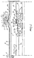
- figure 1 is a schematic view, taken from the side of the needle cylinder, of the needle actuation cams and of the casting-off sinkers, developed on a plane, of the machine according to the invention, indicating the paths of the heels of the needles in the rotary motion of the needle cylinder, with respect to said cams, in one direction;
- figure 2 is a view, taken similarly to figure 1, which indicates the paths of the needle heels in the rotary motion of the needle cylinder, with respect to said cams, in the opposite direction;
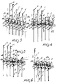
- figures 3 to 6 are schematic perspective views of the position of some needles and casting-off sinkers, developed on a plane, during their passage proximate to a feed of the machine.
- With reference to the above figures, the machine according to the invention comprises, in a known manner, a needle cylinder 1 which can be actuated with rotary motion about its own axis. The cylinder 1 is arranged vertically and has a plurality of axial grooves 2 in each of which a
needle 3 is slideably accommodated. - The machine furthermore has, in a known manner, an annular body, not illustrated for the sake of simplicity, which is rigidly associated with the needle cylinder 1 around its upper end and has a plurality of radial grooves inside which the casting-off
sinkers 4 are slidingly accommodated. - Each of the radial grooves, and accordingly each of the casting-off
sinkers 4, is arranged between two contiguous axial grooves 2 of the needle cylinder 1. - The casting-off
sinkers 4 are conveniently of the type with two casting-off planes 4b and 4c arranged at mutually different vertical levels to form towelling stitches and have aprotuberance 4d for tensioning the formed knitting. - Needle actuation cams are arranged around the needle cylinder 1 and define paths for the heels 3a of the
needles 3 which protrude radially from the grooves 2 of the needle cylinder so as to control the needles along the grooves 2 when the needle cylinder is actuated with a rotary motion about its own axis with respect to said cams. - A
cam 5 with an annular extension is thus furthermore provided and is arranged around the needle cylinder 1, proximate to its upper end, so as to radially actuate the casting-off sinkers. - More particularly, the needle actuation cams comprise a set of knitting forming cams composed of a first lifting cam 6 arranged upstream of a feed 7 of the machine, along a direction of rotation of the needle cylinder indicated by the
arrow 8 in figure 1. - Said first cam 6 defines, upstream of the feed 7 along the
direction 8, two ascending portions 6a and 6b which are engageable by the heel 3a of the needles which must knit at said feed 7 to move the needles into a position suitable for engaging the fed threads 9 and 10. - The knitting-forming cam set comprises a central cam 11 which is arranged at the feed 7 and defines a first descending portion 11a which can engage the heel 3a of the needles which have engaged the threads at the feed 7.
- The needles excluded from knitting at the feed 7, for example during the forming of the heel or of the tip of a sock or stocking, pass with their heel above the central cam 11.
- According to the invention, above the central cam 11 there is an
additional cam 12 which defines a descendingportion 12a which can engage the heel of the needles excluded from knitting at the feed 7 so as to achieve a controlled lowering of theloops 13 carried by the needles excluded from knitting during the feed of the threads to the needles which knit at said feed 7. - Said
additional cam 12 furthermore defines a further descending portion 12b which is substantially symmetrical with respect to the feed 7 of theportion 12a and is engageable with the heel 3a of the needles excluded from knitting when the needle cylinder is actuated with a rotary motion in the direction opposite to the one indicated by thearrow 8 in figure 1, i.e. in the direction indicated by thearrow 14 in figure 2. - Thus the central cam 11 also defines a further first descending portion 11b for the needles which knit at the feed 7 with the needle cylinder actuated with rotary motion in the
direction 14. Said descending portion 11b is substantially symmetrical to the portion 11a with respect to the feed 7. - The descent of the needles which have engaged the threads at the feed 7, with the needle cylinder actuated along the direction of
rotation 14, is completed by a descending portion 6c defined by the cam 6. - The knitting-forming cam set is completed by a
cam 15 which is substantially symmetrical to the cam 6 with respect to the feed 7. Saidcam 15 in fact has two ascendingportions 15a and 15b, for lifting the needles which must knit at the feed 7 when the needle cylinder rotates in thedirection 14, and a descending portion 15c for the needles which have engaged the threads at the feed 7 when the needle cylinder rotates in thedirection 8. In some cases, such as the illustrated one, acam 60 which raises the needles upstream of thecam 15 may be provided. - The
sinker actuation cam 5 defines a path for theheel 4a of thesinkers 4. Said path has, in a known manner, aportion 16 which is proximate to the needle cylinder axis upstream and downstream of the feed 7 and aportion 17 which is spaced from the needle cylinder axis at the feed 7. - In this manner, the
protuberances 4d of thesinkers 4 engage the loops formed around the stem of the needles when their heel follows theportion 16 to tense said loops in the direction of the needle cylinder axis, whereas theprotuberance 4d is disengaged from the loops when theirheel 4a follows theportion 17. - Advantageously, the needle actuation cams furthermore comprise a
lifting cam 18 which is engageable with the heel of the needles excluded from knitting at the feed 7. Said liftingcam 18 is arranged upstream of the cam 6 along the direction ofrotation 8 of the needle cylinder and at theportion 16 defined by thesinker actuation cam 5. - Upstream of the
cam 15 along the direction ofrotation 14 of the needle cylinder there is also alifting cam 19 which corresponds to thecam 18. Both in therotation direction 8 and in thereverse direction 14, thelifting cams - A plurality of thread guides, indicated by the
reference numerals 20 to 26, is provided at the feed 7; the central one 23 of said thread guides preferably feeds the thread 9 which is intended to rest on the lower casting-off plane 4b. - The operation of the machine according to the invention is now described with reference to the production of a row of knitting with towelling stitches during the knitting of the heel or tip of a sock or stocking.
- For the sake of greater clarity, in figures 3 to 6 the letters A, B, C, D, E indicate contiguous needles, of which: the needles A and B are excluded from knitting at the feed 7, the needle C is excluded from knitting just before reaching the feed 7 and the needles D, E knit at the feed 7.
- Figures 1 and 2 instead show in broken lines, and indicate with the
reference numerals reference numeral 51 equally indicates the path followed by the sinker heel along thecam 5. - With particular reference to figure 1, during the rotation of the needle cylinder in the
direction 8, the needles excluded from knitting, before reaching the feed 7, are lifted by thecam 18, whereas the loops carried by said needles are tensioned on their stem by thesinkers 4 in the direction of the needle cylinder axis. In this manner said loops do not follow the needles in their ascent. - Subsequently, by encountering the
additional cam 12, the needles excluded from knitting are lowered, whereas thesinkers 4 do not tense the loops on said needles. In this manner, the lowering of these needles achieves, by traction, the lowering of the loops on their stem. - In particular, the loops carried by the last needles excluded from knitting at the feed 7 undergo this lowering, thus avoiding the upward traction effect which can be observed in known machines and is performed by said loops on the threads 9 and 10 fed to the first needles which must knit at the feed 7 and which, in the meantime, have been lifted into a position suitable for engaging the threads.
- The lowering of the needles excluded from knitting at the feed 7 is shown in figures 3 and 4, wherein the needles A and B undergo said lowering, whereas the needle C is excluded from the knitting or raised to the same level as the needles A and B to perform a so-called "narrowing". It should be noted that the needle C, which is excluded from knitting, is not raised to the level occupied by the needles A and B upstream of the
additional cam 12 but only to the level occupied by the needles A and B after they have been lowered by thecam 12. - This reduced raise of the needle C, which is excluded from the knitting, reduces the upward traction effect performed by said needle on the threads 9 and 10.
- In this manner, the needles D and E, by encountering the central cam 11, are lowered, and thus engage the threads 9 and 10 which rest correctly on the casting-off planes 4b and 4c of the
sinkers 4. - When the needle cylinder rotates in the
opposite direction 14, the movements performed by the cams on the needles are similar to those described above. - In practice it has been observed that the machine according to the invention fully achieves the intended aim, since by virtue of the lowering of the needles excluded from knitting at the feed being considered, it reduces or even eliminates the effect of upward traction of the threads fed by said feed, thus allowing the correct forming of towelling stitches even with very fine knitting and with scarcely elastic threads.
- The machine thus conceived is susceptible to numerous modifications and variations, all of which are within the scope of the inventive concept; all the details may furthermore be replaced with technically equivalent elements.
- Although the machine according to the invention has been conceived in particular for the knitting of towelling stitches in sock or stocking manufacture, the concept underlying the invention can be used successfully for other types of knitting as well.
- In practice, the materials employed, as well as the dimensions, may be any according to the requirements and to the state of the art.
- Where technical features mentioned in any claim are followed by reference signs, those reference signs have been included for the sole purpose of increasing the intelligibility of the claims and accordingly such reference signs do not have any limiting effect on the scope of each element identified by way of example by such reference signs.
Claims (13)
- Circular knitting machine for socks, stockings or the like, in particular for producing knitting with towelling stitches, comprising a needle cylinder having a skirt and being activatable with a rotary motion about its own needle cylinder axis, a plurality of axial grooves defined on the outer surface of said skirt, each of said grooves slideably accommodating a needle, needle actuation cams facing said skirt of said needle cylinder and defining paths for heels of said needles which protrude radially from said grooves, a plurality of casting-off sinkers being provided, each casting-off sinker being arranged between two contiguous axial grooves of said needle cylinder, proximate to an upper end thereof, said sinkers being radially movable with respect to said needle cylinder to tension loops formed by said needles; said needle actuation cams comprising, upstream of at least one thread feed along the direction of rotation of the needle cylinder about said needle cylinder axis with respect to said needle actuation cams, at least one lifting cam for lifting the needles into a position suitable for gripping at least one thread fed by said thread feed and, successively to said lifting cam, a central cam defining a first descending portion for needles which knit at said feed, characterized in that above said central cam there is an additional cam defining a descending portion engageable with heels of needles excluded from knitting at said thread feed for controlled lowering of loops carried by said needles excluded from knitting during the feed of said at least one thread to the needles which knit at said feed.
- Machine according to claim 1, characterized in that upstream of said additional cam, along the direction of rotation of the needle cylinder relatively to said needle actuation cams, there is a lifting cam which is engageable with the heel of the needles excluded from knitting at said feed.
- Machine according to claims 1 and 2, characterized in that said lifting cam is arranged upstream of said lifting cam along the direction of rotation of the needle cylinder relatively to said needle actuation cams.
- Machine according to one or more of the preceding claims, characterized in that it comprises at least one casting-off sinker actuation cam defining a path for a sinker heel and extending around the needle cylinder axis, said sinker heel path having at least one portion proximate to the needle cylinder axis, along which said sinkers are in a position in which they engage loops carried by the needles to tension them in the direction of the needle cylinder axis, and a portion spaced from the needle cylinder axis, along which said sinkers are in a position for releasing loops carried by the needles, said portion spaced from the needle cylinder axis being arranged at said thread feed.
- Machine according to one or more of the preceding claims, characterized in that said lifting cam is arranged at said portion proximate to the needle cylinder axis in the path defined by the casting-off sinker actuation cams to lift needles which do not knit at said thread feed with said sinkers in a position for engagement with loops carried by said needles which do not knit.
- Machine according to one or more of the preceding claims, characterized in that each of said sinkers defines two casting-off planes, arranged at different levels, for two threads fed at said feed to form towelling stitches.
- Machine according to one or more of the preceding claims, characterized in that said feed comprises at least two thread guides, a first thread guide having a thread feed end arranged at a higher level with respect to the feed end of a second thread guide.
- Machine according to one or more of the preceding claims, characterized in that said additional cam has a profile defining a descending portion, engageable with heels of needles excluded from knitting at said thread feed, in both of the directions of rotation of the needle cylinder.
- Machine according to one or more of the preceding claims, characterized in that it comprises a further lifting cam arranged downstream of said feed, along the direction of rotation of the needle cylinder relatively to said actuation cams, said lifting cam being engageable with heels of needles excluded from knitting at said thread feed to lift said heels after the lowering performed by said additional cam.
- Machine according to one or more of the preceding claims, characterized in that said lifting cam and said further lifting cam have a profile defining ascending portions for heels of needles excluded from knitting at said thread feed in both of the directions of rotation of the needle cylinder.
- Process for forming towelling stitches with a circular knitting machine for socks, stockings or the like, comprising the step of knitting a row of knitting with part of the needles excluded from knitting at one feed, and raised with respect to the needles which knit at said feed, characterized in that proximate to said feed the needles excluded from knitting are subjected to a controlled lowering.
- Process according to claim 11, characterized in that during said controlled lowering of said needles excluded from knitting at said feed the casting-off sinkers are in a position for releasing loops carried by the needles.
- Process according to claim 11, characterized in that upstream of said feed along the direction of rotation of the needle cylinder with respect to the needle actuation cams said needles excluded from knitting at said feed are subjected to a controlled lifting with said casting-off sinkers engaged with the loops carried by the needles.
Applications Claiming Priority (2)
| Application Number | Priority Date | Filing Date | Title |
|---|---|---|---|
| IT2092890 | 1990-07-13 | ||
| IT02092890A IT1246361B (en) | 1990-07-13 | 1990-07-13 | CIRCULAR MACHINE FOR KNITWEAR, FOOTWEAR OR SIMILAR, IN PARTICULAR FOR THE PERFORMANCE OF WORKING WITH SPONGE STITCHES. |
Publications (2)
| Publication Number | Publication Date |
|---|---|
| EP0466072A2 true EP0466072A2 (en) | 1992-01-15 |
| EP0466072A3 EP0466072A3 (en) | 1992-02-19 |
Family
ID=11174212
Family Applications (1)
| Application Number | Title | Priority Date | Filing Date |
|---|---|---|---|
| EP19910111340 Withdrawn EP0466072A3 (en) | 1990-07-13 | 1991-07-08 | Circular knitting machine for socks, stockings or the like, in particular for producing knitting with towelling stitches |
Country Status (5)
| Country | Link |
|---|---|
| US (1) | US5170649A (en) |
| EP (1) | EP0466072A3 (en) |
| JP (1) | JPH04272258A (en) |
| CS (1) | CS217091A3 (en) |
| IT (1) | IT1246361B (en) |
Cited By (1)
| Publication number | Priority date | Publication date | Assignee | Title |
|---|---|---|---|---|
| IT201800007018A1 (en) * | 2018-07-06 | 2020-01-06 | METHOD OF MAKING A KNITTING STITCH IN A KNITTING MACHINE WITH ONE OR MORE FALLS |
Families Citing this family (6)
| Publication number | Priority date | Publication date | Assignee | Title |
|---|---|---|---|---|
| WO2005054557A1 (en) * | 2003-12-01 | 2005-06-16 | Hui Seong Lee | Circular knitting machine for both-sided velour textile |
| KR100551475B1 (en) * | 2004-08-31 | 2006-02-14 | 삼성전자주식회사 | Memory module with aperiodic clock option and memory chip and hub chip for using the same |
| ITMN20110014A1 (en) * | 2011-04-20 | 2012-10-21 | Luigi Redini | SOCKS FOR STIMULATION OF FOOT AREAS. |
| JP5987180B2 (en) * | 2012-02-15 | 2016-09-07 | 岡本株式会社 | Knitting machine capable of changing pile length and manufacturing method of knitted fabric with changed pile length |
| PL3191634T3 (en) * | 2014-09-11 | 2022-07-18 | Calzificio Pinelli S.R.L. | Method for manufacturing tubular articles provided with a grip region by way of circular hosiery knitting machines, and tubular article obtained with the method |
| WO2016066573A1 (en) * | 2014-10-29 | 2016-05-06 | Lonati S.P.A. | Circular machine for knitting, hosiery or the like, with sinker actuation device |
Citations (5)
| Publication number | Priority date | Publication date | Assignee | Title |
|---|---|---|---|---|
| GB1229047A (en) * | 1967-04-25 | 1971-04-21 | ||
| GB2062019A (en) * | 1979-09-28 | 1981-05-20 | Elitex Zavody Textilniho | Cam system for double-cylinder knitting-machine |
| GB2144154A (en) * | 1983-07-28 | 1985-02-27 | Elitex Zavody Textilniho | Circular knitting machine |
| DE3725151A1 (en) * | 1986-07-29 | 1988-02-04 | Elitex Zavody Textilniho | SINGLE-CYLINDER CIRCULAR KNITTING MACHINE FOR THE PRODUCTION OF HOSPITALS |
| EP0225502B1 (en) * | 1985-12-02 | 1990-09-05 | LONATI S.p.A. | Twin-cylinder circular knitting machine with a perfected device for actuating the transfer sinker |
Family Cites Families (4)
| Publication number | Priority date | Publication date | Assignee | Title |
|---|---|---|---|---|
| US2134480A (en) * | 1935-01-25 | 1938-10-25 | Standard Trump Bros Machine Co | Knitting method and machine |
| DE3024705C2 (en) * | 1980-06-30 | 1986-04-30 | Schmidt, Ursula Dorothea, 6082 Mörfelden-Walldorf | Process for the production of patterned plush goods, as well as circular knitting machine for this |
| GB2131053B (en) * | 1982-09-08 | 1986-01-29 | Okamoto Co Ltd | Circular knitting machines |
| SU1280056A1 (en) * | 1983-02-28 | 1986-12-30 | Московский Ордена Трудового Красного Знамени Текстильный Институт Им.А.Н.Косыгина | Method of knitting single weft-knitted plush fabric |
-
1990
- 1990-07-13 IT IT02092890A patent/IT1246361B/en active IP Right Grant
-
1991
- 1991-06-28 US US07/723,115 patent/US5170649A/en not_active Expired - Fee Related
- 1991-07-08 EP EP19910111340 patent/EP0466072A3/en not_active Withdrawn
- 1991-07-11 JP JP3170849A patent/JPH04272258A/en active Pending
- 1991-07-12 CS CS912170A patent/CS217091A3/en unknown
Patent Citations (5)
| Publication number | Priority date | Publication date | Assignee | Title |
|---|---|---|---|---|
| GB1229047A (en) * | 1967-04-25 | 1971-04-21 | ||
| GB2062019A (en) * | 1979-09-28 | 1981-05-20 | Elitex Zavody Textilniho | Cam system for double-cylinder knitting-machine |
| GB2144154A (en) * | 1983-07-28 | 1985-02-27 | Elitex Zavody Textilniho | Circular knitting machine |
| EP0225502B1 (en) * | 1985-12-02 | 1990-09-05 | LONATI S.p.A. | Twin-cylinder circular knitting machine with a perfected device for actuating the transfer sinker |
| DE3725151A1 (en) * | 1986-07-29 | 1988-02-04 | Elitex Zavody Textilniho | SINGLE-CYLINDER CIRCULAR KNITTING MACHINE FOR THE PRODUCTION OF HOSPITALS |
Cited By (3)
| Publication number | Priority date | Publication date | Assignee | Title |
|---|---|---|---|---|
| IT201800007018A1 (en) * | 2018-07-06 | 2020-01-06 | METHOD OF MAKING A KNITTING STITCH IN A KNITTING MACHINE WITH ONE OR MORE FALLS | |
| WO2020007764A1 (en) * | 2018-07-06 | 2020-01-09 | Jvc Holding Srl | Method for making a knitting stitch in a knitting machine with one or more feeders |
| US11542642B2 (en) | 2018-07-06 | 2023-01-03 | Jvc Holding Srl | Method for making a knitting stitch in a knitting machine with one or more feeders |
Also Published As
| Publication number | Publication date |
|---|---|
| JPH04272258A (en) | 1992-09-29 |
| IT9020928A0 (en) | 1990-07-13 |
| IT1246361B (en) | 1994-11-17 |
| EP0466072A3 (en) | 1992-02-19 |
| IT9020928A1 (en) | 1992-01-13 |
| CS217091A3 (en) | 1992-01-15 |
| US5170649A (en) | 1992-12-15 |
Similar Documents
| Publication | Publication Date | Title |
|---|---|---|
| US3430463A (en) | Method and apparatus for making run-resistant knitted fabric | |
| ITBS20080176A1 (en) | CIRCULAR MACHINE FOR KNITWEAR AND FOOTWEAR | |
| EP0756029A1 (en) | Method for manufacturing socks or the like having a closed toe with a single-cylinder circular knitting machine | |
| JP3455562B2 (en) | Multi-yarn feed circular knitting machine | |
| US5170649A (en) | Circular knitting machine for socks, stockings or the like, in particular for producing knitting with towelling stitches | |
| US3254509A (en) | Circular knitting machines for the production of hosiery with double, outwardly turned-over welts | |
| US3301012A (en) | Circular knitting machines for the production of hosiery with double, outwardly turned-over welts | |
| US5335518A (en) | Circular knitting machine for manufacturing socks, stockings and the like, with device for producing patterns with toweling stitches | |
| US6609395B2 (en) | Double-cylinder circular stocking knitting machine with structurally highly simplified cam box | |
| US5072603A (en) | Knitting machine with needle control device for the knitting of pattern stitches | |
| US3877256A (en) | Knitting method and apparatus utilizing cylinder and dial needles | |
| US2207463A (en) | Selective control of sinkers, needles, and jacks | |
| JPH04228658A (en) | Circular knitting machine | |
| US3964275A (en) | Terry loop forming instrument for circular knitting machine | |
| US1961636A (en) | Method of knitting multithread fabric | |
| US3435636A (en) | Stitch cam and method of knitting semidrawn yarn | |
| US3879962A (en) | Fabric hold-down blade for circular hosiery knitting machines | |
| USRE24616E (en) | And methxd xf kmixb | |
| US2191378A (en) | Circular rib knitting machine and method of operating same | |
| US3478544A (en) | Method of knitting sheer seamless support stockings | |
| CN112352074B (en) | Method for producing loop-forming loops in a knitting machine with one or more feeders | |
| US2230213A (en) | Wrap stripe knitting machine | |
| US3106830A (en) | Run resistant fabric | |
| US3260072A (en) | Knitting machine | |
| US3000199A (en) | Knitting machine and method |
Legal Events
| Date | Code | Title | Description |
|---|---|---|---|
| PUAI | Public reference made under article 153(3) epc to a published international application that has entered the european phase |
Free format text: ORIGINAL CODE: 0009012 |
|
| PUAL | Search report despatched |
Free format text: ORIGINAL CODE: 0009013 |
|
| AK | Designated contracting states |
Kind code of ref document: A2 Designated state(s): DE FR GB |
|
| AK | Designated contracting states |
Kind code of ref document: A3 Designated state(s): DE FR GB |
|
| 17P | Request for examination filed |
Effective date: 19920704 |
|
| RAP1 | Party data changed (applicant data changed or rights of an application transferred) |
Owner name: LONATI S.P.A. |
|
| 17Q | First examination report despatched |
Effective date: 19950217 |
|
| STAA | Information on the status of an ep patent application or granted ep patent |
Free format text: STATUS: THE APPLICATION HAS BEEN WITHDRAWN |
|
| 18W | Application withdrawn |
Withdrawal date: 19950619 |