EP0453617A1 - Ship for carrying liquefied gas - Google Patents
Ship for carrying liquefied gas Download PDFInfo
- Publication number
- EP0453617A1 EP0453617A1 EP90108131A EP90108131A EP0453617A1 EP 0453617 A1 EP0453617 A1 EP 0453617A1 EP 90108131 A EP90108131 A EP 90108131A EP 90108131 A EP90108131 A EP 90108131A EP 0453617 A1 EP0453617 A1 EP 0453617A1
- Authority
- EP
- European Patent Office
- Prior art keywords
- hull
- liquefied gas
- cargo tanks
- upper deck
- gas carrier
- Prior art date
- Legal status (The legal status is an assumption and is not a legal conclusion. Google has not performed a legal analysis and makes no representation as to the accuracy of the status listed.)
- Withdrawn
Links
Images


Classifications
-
- B—PERFORMING OPERATIONS; TRANSPORTING
- B63—SHIPS OR OTHER WATERBORNE VESSELS; RELATED EQUIPMENT
- B63B—SHIPS OR OTHER WATERBORNE VESSELS; EQUIPMENT FOR SHIPPING
- B63B25/00—Load-accommodating arrangements, e.g. stowing, trimming; Vessels characterised thereby
- B63B25/02—Load-accommodating arrangements, e.g. stowing, trimming; Vessels characterised thereby for bulk goods
- B63B25/08—Load-accommodating arrangements, e.g. stowing, trimming; Vessels characterised thereby for bulk goods fluid
- B63B25/12—Load-accommodating arrangements, e.g. stowing, trimming; Vessels characterised thereby for bulk goods fluid closed
Definitions
- the present invention relates to a liquefied gas carrier, and more particularly to a liquefied gas carrier having an improved hull structure.
- spherical cargo tanks 2 are fixed on a foundation deck 3 of a carrier by means of cylindrical skirts 4, and hemi-spherical tank covers 7 for shielding the portions of the above-mentioned spherical cargo tanks protruding above an upper deck 5 from the open air are disposed as projecting above the aforementioned upper deck 5.
- Numeral 12 denotes a pipe tower in which oil pipes,etc. are installed.
- reference numeral 6 designates a side double hull
- numeral 8 designates a side plating
- numeral 10 designates an upper construction.
- a liquefied gas carrier which comprises a plurality of cargo tanks arrayed in the length-wise direction of a hull, cylindrical skirts for holding the cargo tanks within a hold, and an upper deck covering the upper side of these cargo tanks and being continuous in the lengthwise direction of the hull, each of the cargo tanks being formed in a flat spherical shape with its diameter in the vertical direction shortened with respect to its diameter in the equatorial plane.
- the upper deck is formed of a sheet member that is continuous in the lengthwise direction of the hull, the upper deck can act as a longitudinal strength member of the hull.
- the height of the upper structure of ships can be reduced.
- cargo tanks 11 disposed on a foundation deck 3 of a liquefied gas carrier 1 are formed in a flat spherical shape with its diameter in the vertical direction shortened with respect to its diameter in the equatorial plane, and four such cargo tanks 11 are fixedly arrayed in the lengthwise direction of the hull on the foundation deck 3 of the liquefied gas carrier 1 by means of cylindrical skirts 4.
- a flat upper deck 5 that is continuous in the lengthwise direction of the hull and covers the upper side of these cargo tanks.
- Numeral 9 denotes a flying passage.
- the both side edge portions 5a of the upper deck 5 are formed in a downwardly tilted shape so as to follow the profiles of the flat spherical cargo tanks 11 as shown in Fig. 3. Accordingly, in the case of the second preferred embodiment, a wind resistance against lateral wind can be reduced as compared to the first preferred embodiment shown in Fig. 2.
- numeral 12 denotes a pipe tower in which oil pipes, etc. are installed.
- the upper deck covering the upper side of the cargo tanks is formed so as to be continuous in the lengthwise direction of the hull and in a flat shape owing to the above-described construction, the effect of the upper deck as a longitudinal strength member of the hull can be enhanced, and for instance, in a liquefied gas carrier consisting of four tanks having a loading capacity of 125,000 m3, a hull weight can be reduced by about 1000 tons as compared to the liquefied gas carriers in the prior art.
- FIGs. 2 and 3 are illustrations of cargo tanks having the same capacity on the same scale, and in the case of liquefied gas carriers consisting of four tanks having a loading capacity of 125,000 m3, in contrast to the fact that the spherical cargo tank in the prior art had a diameter of about 40 m, the height of the upper deck according to the present invention can be lowered by about 6 m as compared to the height of the tank cover in the prior art.
- the cargo tank is supported only by the skirts 4 as the prior MOSS type spherical tank. Accordingly, there is space between the bottom of the tank 11 and the foundation deck 3 or the inner bottom plate of the two-fold bottom.
- the tank is not supported by heat insulating material.
- the strength of the bottom of the spherical tank supported by the skirts is obtained by its curvature against the inner pressure and the pressure of the liquid. This is also true in the case of a non-spherical tank of this invention.
- the required thickness t of the spherical cell subjected to the inner pressure is:
- the tank is comprised of the cylindrical equatorial portion, the top portion with panel structure and the bottom composed of an elliptical body whose longer axis length is equal to the radius of the equatorial portion or the bottom composed of semi-elliptical body which is the combination of circular arcs.
- the liquefied gas carrier according to the present invention provides the following effects and advantages:
Landscapes
- Chemical & Material Sciences (AREA)
- Engineering & Computer Science (AREA)
- Combustion & Propulsion (AREA)
- Mechanical Engineering (AREA)
- Ocean & Marine Engineering (AREA)
- Filling Or Discharging Of Gas Storage Vessels (AREA)
Abstract
Description
- The present invention relates to a liquefied gas carrier, and more particularly to a liquefied gas carrier having an improved hull structure.
- In a MOSS type
liquefied gas carrier 1 in the prior art, as shown in Fig. 4 (a longitudinal cross-section view of a hull) and in Fig. 5 (a transverse cross-section view of a hull),spherical cargo tanks 2 are fixed on afoundation deck 3 of a carrier by means ofcylindrical skirts 4, and hemi-spherical tank covers 7 for shielding the portions of the above-mentioned spherical cargo tanks protruding above anupper deck 5 from the open air are disposed as projecting above the aforementionedupper deck 5. Numeral 12 denotes a pipe tower in which oil pipes,etc. are installed. - Moreover, in the MOSS type liquefied
gas carrier 1 in the prior art, since pipings for cargo liquid must be disposed at the top of thecargo tanks 2, aflying passage 9 is disposed at the tops of the aforementioned tank covers 7, and pipings are arranged thereon. - It is to be noted that reference numeral 6 designates a side double hull,
numeral 8 designates a side plating, andnumeral 10 designates an upper construction. - However, in the MOSS type liquefied gas carrier in the prior art having the aforementioned construction, due to the fact that
spherical cargo tanks 2 and tank covers 7 covering the tanks projected above anupper deck 5, it involved the following problems: - (1) Since circular cut openings are formed in the upper deck due to protrusion of the cargo tanks, continuity of the upper deck is interrupted, resulting in that the portion of the upper deck serving as an effective member for maintaining a longitudinal strength of the hull is limited to the side portions of the upper deck, and therefore, in order to insure a longitudinal strength of the hull, it is necessary to greatly increase a thickness of the members in the proximity of the upper deck. (It is to be noted that the tank covers do not contribute to the longitudinal strength of the hull.)
- (2) Due to the fact that the configuration of the structure above the upper deck is complicated as compared to common ships, a wind resistance against lateral wind is so large that upon approach to a shore or upon loading and unloading of cargo liquid, tilting of a hull is liable to occur as fanned by strong wind.
- (3) As a flying passage is disposed at a position considerably higher than the upper deck (for instance, at a height of about 15 - 20 m in the case of a liquefied gas carrier of 125,000 m³ loading class) and pipings and electric wirings are arranged on the flying passage, rigging work would become aerial works, and moreover, after entering navigation service also, maintenance works for pipings and valves would become aerial works and a working efficiency is poor.
- (4) Due to interception of view by the tank covers 7, front perspective upon manoeuvre is poor as compared to common ships, and in order to compensate for that defect, the upper structure must be made unnecessarily high, and this is uneconomical.
- It is therefore one object of the present invention to provide a liquefied gas carrier having the effect of the upper deck as a longitudinal strength (reinforcing) member of a hull enlarged and having the height of the upper structure lowered.
- According to one feature of the present invention, there is provided a liquefied gas carrier, which comprises a plurality of cargo tanks arrayed in the length-wise direction of a hull, cylindrical skirts for holding the cargo tanks within a hold, and an upper deck covering the upper side of these cargo tanks and being continuous in the lengthwise direction of the hull, each of the cargo tanks being formed in a flat spherical shape with its diameter in the vertical direction shortened with respect to its diameter in the equatorial plane.
- In the liquefied gas carrier according to the present invention as featured above, since the upper deck is formed of a sheet member that is continuous in the lengthwise direction of the hull, the upper deck can act as a longitudinal strength member of the hull.
- Also, according to the present invention, the height of the upper structure of ships can be reduced.
- The above-mentioned and other objects, features and advantages of the present invention will become more apparent by reference to the following description of preferred embodiments of the invention taken in conjunction with the accompanying drawings.
- In the accompanying drawings:
- Fig. 1 is a longitudinal cross-section view of a hull of a liquefied gas carrier according to a first preferred embodiment of the present invention;
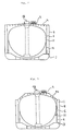
- Fig. 2 is a transverse cross-section view of the same hull;
- Fig. 3 is a transverse cross-section view of a hull of a liquefied gas carrier according to a second preferred embodiment of the present invention;
- Fig. 4 is a longitudinal cross-section view of a hull of a liquefied gas carrier in the prior art; and
- Fig. 5 is a transverse cross section view of the same hull.
- In the following, the present invention will be described in greater detail in connection to the first preferred embodiment of the invention illustrated in Figs. 1 and 2 and the second preferred embodiment thereof illustrated in Fig. 3.
- In these preferred embodiment,
cargo tanks 11 disposed on afoundation deck 3 of aliquefied gas carrier 1 are formed in a flat spherical shape with its diameter in the vertical direction shortened with respect to its diameter in the equatorial plane, and foursuch cargo tanks 11 are fixedly arrayed in the lengthwise direction of the hull on thefoundation deck 3 of the liquefiedgas carrier 1 by means ofcylindrical skirts 4. - In addition, there is provided a flat
upper deck 5 that is continuous in the lengthwise direction of the hull and covers the upper side of these cargo tanks.Numeral 9 denotes a flying passage. - While the
upper deck 5 is almost flat in the lateral direction in the first preferred embodiment illustrated in Figs. 1 and 2, in the second preferred embodiment the bothside edge portions 5a of theupper deck 5 are formed in a downwardly tilted shape so as to follow the profiles of the flatspherical cargo tanks 11 as shown in Fig. 3. Accordingly, in the case of the second preferred embodiment, a wind resistance against lateral wind can be reduced as compared to the first preferred embodiment shown in Fig. 2. In Figs.2 and 3,numeral 12 denotes a pipe tower in which oil pipes, etc. are installed. - Since the upper deck covering the upper side of the cargo tanks is formed so as to be continuous in the lengthwise direction of the hull and in a flat shape owing to the above-described construction, the effect of the upper deck as a longitudinal strength member of the hull can be enhanced, and for instance, in a liquefied gas carrier consisting of four tanks having a loading capacity of 125,000 m³, a hull weight can be reduced by about 1000 tons as compared to the liquefied gas carriers in the prior art.
- Moreover, the height of upper structure of ships can be lowered. For instance, Figs. 2 and 3 are illustrations of cargo tanks having the same capacity on the same scale, and in the case of liquefied gas carriers consisting of four tanks having a loading capacity of 125,000 m³, in contrast to the fact that the spherical cargo tank in the prior art had a diameter of about 40 m, the height of the upper deck according to the present invention can be lowered by about 6 m as compared to the height of the tank cover in the prior art.
- In this invention, the cargo tank is supported only by the
skirts 4 as the prior MOSS type spherical tank. Accordingly, there is space between the bottom of thetank 11 and thefoundation deck 3 or the inner bottom plate of the two-fold bottom. The tank is not supported by heat insulating material. - There is no problem on the strenght of the bottom of the tank, etc.
The reason is as follows: - The strength of the bottom of the spherical tank supported by the skirts is obtained by its curvature against the inner pressure and the pressure of the liquid. This is also true in the case of a non-spherical tank of this invention. For example, the required thickness t of the spherical cell subjected to the inner pressure is:

- In case of the non-spherical tank, R becomes 1.5 - 2.0 times compared to that of the spherical tank. However, this can be solved by increasing partly the thickness of the tank, and this increased thickness can be practically realized. Accordingly, there is no problem on the strength in this invention.
- The following shape of the non-spherical tank may be explained as an example of this invention:
The tank is comprised of the cylindrical equatorial portion, the top portion with panel structure and the bottom composed of an elliptical body whose longer axis length is equal to the radius of the equatorial portion or the bottom composed of semi-elliptical body which is the combination of circular arcs. - As described in detail above, the liquefied gas carrier according to the present invention provides the following effects and advantages:
- (1) Owing to the fact that cargo tanks of flat spherical shape are used and the upper deck is formed in a flat shape that is continuous in the longitudinal direction of the hull, the height of the upper deck can be made remarkably low as compared to the top of the tank covers of the liquefied gas carrier in the prior art (for instance, in the case of a four-tank carrier having a loading capacity of 125,000 m³, it can be lowered by about 6 m) without increasing a weight of the hull.
- (2) The height of the upper structure can be made low (in the case of the above-mentioned example, it can be lowered by about 6 m corresponding to two floors), and so a wind resistance can be reduced.
- (3) A flying passage and tank covers can be eliminated, and in addition, aerial work for rigging work of pipings as well as maintenance of pipings and valves can be dispensed.
- While a principle of the present invention has been described above in connection to preferred embodiments of the invention, it is intended that all matter contained in the above description and illustrated in the accompanying drawings shall be interpreted to be illustrative and not in a limiting sense.
Claims (3)
- A liquefied gas carrier, characterized in that said carrier comprises a plurality of cargo tanks arrayed in the lengthwise direction of a hull and cylindrical skirts for holding said cargo tanks within a hold, each said cargo tank is formed in a flat spherical shape with its diameter in the vertical direction shortened with respect to its diameter in the equatorial plane, and also there is provided an upper deck covering the upper side of these cargo tanks and being continuous in the lengthwise direction of the hull.
- A liquefied gas carrier as claimed in Claim 1, wherein said upper deck which is continuous in the lengthwise direction is flat.
- A liquefied gas carrier as claimed in Claim 1 or 2, wherein the both side edge portions of said upper deck which is continuous in the lengthwise direction are formed to be inclined downwards so as to conform to the shape of the flat cargo tanks.
Priority Applications (3)
| Application Number | Priority Date | Filing Date | Title |
|---|---|---|---|
| DE1990108131 DE453617T1 (en) | 1990-04-27 | 1990-04-27 | SHIP FOR TRANSPORTING LIQUID GAS. |
| ES90108131T ES2027939T1 (en) | 1990-04-27 | 1990-04-27 | BOAT FOR THE TRANSPORTATION OF LIQUEFIED GAS. |
| EP90108131A EP0453617A1 (en) | 1990-04-27 | 1990-04-27 | Ship for carrying liquefied gas |
Applications Claiming Priority (1)
| Application Number | Priority Date | Filing Date | Title |
|---|---|---|---|
| EP90108131A EP0453617A1 (en) | 1990-04-27 | 1990-04-27 | Ship for carrying liquefied gas |
Publications (1)
| Publication Number | Publication Date |
|---|---|
| EP0453617A1 true EP0453617A1 (en) | 1991-10-30 |
Family
ID=8203932
Family Applications (1)
| Application Number | Title | Priority Date | Filing Date |
|---|---|---|---|
| EP90108131A Withdrawn EP0453617A1 (en) | 1990-04-27 | 1990-04-27 | Ship for carrying liquefied gas |
Country Status (3)
| Country | Link |
|---|---|
| EP (1) | EP0453617A1 (en) |
| DE (1) | DE453617T1 (en) |
| ES (1) | ES2027939T1 (en) |
Cited By (11)
| Publication number | Priority date | Publication date | Assignee | Title |
|---|---|---|---|---|
| WO1998056651A1 (en) * | 1997-05-30 | 1998-12-17 | Kvaerner Maritime As | Device for offshore lng production |
| GB2365384A (en) * | 2000-07-26 | 2002-02-20 | Timothy John Gunner | Oil tanker with double hulled cargo tanks |
| BE1014085A3 (en) * | 2000-04-19 | 2003-04-01 | Ridder Arthur De | Tank, especially for installation in ship, has ends of roof and floor connected to each other directly or via curved side walls |
| WO2003082665A1 (en) * | 2002-03-28 | 2003-10-09 | Kvaerner Masa-Yards Oy | A method and an arrangement for reducing the weight and optimizing the longitudinal strength of a water-craft |
| WO2005073069A1 (en) * | 2004-01-28 | 2005-08-11 | Moss Maritime As | A lng-carrier with spherical tanks and double bottom |
| CN102958797A (en) * | 2010-09-08 | 2013-03-06 | 三菱重工业株式会社 | Liquefied gas carrying ship |
| CN102991892A (en) * | 2012-12-20 | 2013-03-27 | 武汉武船海洋工程船舶设计有限公司 | Hazardous article storage device |
| RU2522201C1 (en) * | 2013-02-20 | 2014-07-10 | Федеральное государственное унитарное предприятие "Крыловский государственный научный центр" (ФГУП "Крыловский государственный научный центр") | Natural gas tanker to be used, mainly, in arctic waters |
| CN104859802A (en) * | 2014-02-26 | 2015-08-26 | 三菱重工业株式会社 | Carrying Vessel |
| WO2016071557A1 (en) * | 2014-11-06 | 2016-05-12 | Vaasaball Lng Products Oy | Stable tank for liquefied gas or liquid |
| CN107000814A (en) * | 2014-12-25 | 2017-08-01 | 三井造船株式会社 | Possesses the floating structure of liquefied gas storage equipment |
Citations (4)
| Publication number | Priority date | Publication date | Assignee | Title |
|---|---|---|---|---|
| US3011321A (en) * | 1957-12-02 | 1961-12-05 | Texaco Inc | Apparatus for the maintenance of liquefied petroleum products |
| US3859805A (en) * | 1974-02-08 | 1975-01-14 | Chicago Bridge & Iron Co | Flat bottom ship tank for transport of liquefied gas |
| USRE29463E (en) * | 1969-10-10 | 1977-11-01 | Kvaerner Brug A/S | Tanker for liquified and/or compressed gas |
| US4095546A (en) * | 1977-07-14 | 1978-06-20 | Kane John R | Shipboard LNG tanks |
-
1990
- 1990-04-27 EP EP90108131A patent/EP0453617A1/en not_active Withdrawn
- 1990-04-27 DE DE1990108131 patent/DE453617T1/en active Pending
- 1990-04-27 ES ES90108131T patent/ES2027939T1/en active Pending
Patent Citations (4)
| Publication number | Priority date | Publication date | Assignee | Title |
|---|---|---|---|---|
| US3011321A (en) * | 1957-12-02 | 1961-12-05 | Texaco Inc | Apparatus for the maintenance of liquefied petroleum products |
| USRE29463E (en) * | 1969-10-10 | 1977-11-01 | Kvaerner Brug A/S | Tanker for liquified and/or compressed gas |
| US3859805A (en) * | 1974-02-08 | 1975-01-14 | Chicago Bridge & Iron Co | Flat bottom ship tank for transport of liquefied gas |
| US4095546A (en) * | 1977-07-14 | 1978-06-20 | Kane John R | Shipboard LNG tanks |
Non-Patent Citations (2)
| Title |
|---|
| PATENT ABSTRACTS OF JAPAN, no. 12, page 3575 M 77; & JP-A-52 51 688 (HITACHI ZOSEN K.K.) 25-04-1977 * |
| SHIPPING WORLD & SHIPBUILDER, no. 159, September 1966, page 334; ""Teviot" liquid ethylene carrier completed at Burntisland" * |
Cited By (17)
| Publication number | Priority date | Publication date | Assignee | Title |
|---|---|---|---|---|
| WO1998056651A1 (en) * | 1997-05-30 | 1998-12-17 | Kvaerner Maritime As | Device for offshore lng production |
| BE1014085A3 (en) * | 2000-04-19 | 2003-04-01 | Ridder Arthur De | Tank, especially for installation in ship, has ends of roof and floor connected to each other directly or via curved side walls |
| GB2365384A (en) * | 2000-07-26 | 2002-02-20 | Timothy John Gunner | Oil tanker with double hulled cargo tanks |
| GB2365384B (en) * | 2000-07-26 | 2002-06-26 | Timothy John Gunner | Oil tankers |
| KR100977647B1 (en) * | 2002-03-28 | 2010-08-24 | 에스티엑스 핀란드 오와이 | Method for reducing the weight and optimizing the longitudinal strength of a water-craft and water-craft thereof |
| JP2005521589A (en) * | 2002-03-28 | 2005-07-21 | クバエルネル マサ − ヤーズ オサケ ユキチュア | Method and apparatus for reducing ship weight and optimizing longitudinal strength |
| US7174841B2 (en) | 2002-03-28 | 2007-02-13 | Aker Yards Oy | Method and an arrangement for reducing the weight and optimizing the longitudinal strength of a water-craft |
| WO2003082665A1 (en) * | 2002-03-28 | 2003-10-09 | Kvaerner Masa-Yards Oy | A method and an arrangement for reducing the weight and optimizing the longitudinal strength of a water-craft |
| WO2005073069A1 (en) * | 2004-01-28 | 2005-08-11 | Moss Maritime As | A lng-carrier with spherical tanks and double bottom |
| CN102958797A (en) * | 2010-09-08 | 2013-03-06 | 三菱重工业株式会社 | Liquefied gas carrying ship |
| CN102958797B (en) * | 2010-09-08 | 2015-11-25 | 三菱重工业株式会社 | Liquefied gas carrier |
| CN102991892A (en) * | 2012-12-20 | 2013-03-27 | 武汉武船海洋工程船舶设计有限公司 | Hazardous article storage device |
| RU2522201C1 (en) * | 2013-02-20 | 2014-07-10 | Федеральное государственное унитарное предприятие "Крыловский государственный научный центр" (ФГУП "Крыловский государственный научный центр") | Natural gas tanker to be used, mainly, in arctic waters |
| CN104859802A (en) * | 2014-02-26 | 2015-08-26 | 三菱重工业株式会社 | Carrying Vessel |
| JP2015160443A (en) * | 2014-02-26 | 2015-09-07 | 三菱重工業株式会社 | Carrier ship |
| WO2016071557A1 (en) * | 2014-11-06 | 2016-05-12 | Vaasaball Lng Products Oy | Stable tank for liquefied gas or liquid |
| CN107000814A (en) * | 2014-12-25 | 2017-08-01 | 三井造船株式会社 | Possesses the floating structure of liquefied gas storage equipment |
Also Published As
| Publication number | Publication date |
|---|---|
| DE453617T1 (en) | 1992-04-09 |
| ES2027939T1 (en) | 1992-07-01 |
Similar Documents
| Publication | Publication Date | Title |
|---|---|---|
| US12078298B2 (en) | Sealed and thermally insulating tank provided with a loading/unloading tower | |
| EP0453617A1 (en) | Ship for carrying liquefied gas | |
| US5779092A (en) | Baffle system for tank | |
| CN102958797B (en) | Liquefied gas carrier | |
| US5697312A (en) | Gas tanker | |
| US6997132B2 (en) | Semi-submersible offshore vessel and methods for positioning operation modules on said vessel | |
| US4095546A (en) | Shipboard LNG tanks | |
| KR20210018314A (en) | Sealed and insulated tank | |
| JP6609828B2 (en) | Deck placing tank structure, ship, tank installation method and inspection method | |
| US4036394A (en) | Floating roof for liquid storage tanks | |
| KR20220098236A (en) | Cargo Tank Units and Vessels | |
| GB2032506A (en) | Tank | |
| US9919772B2 (en) | Hull support structure of liquefied gas tank and liquefied gas carrier | |
| US4630561A (en) | Ship having standardized access ways | |
| WO2022230752A1 (en) | Cargo ship | |
| JPH0549519B2 (en) | ||
| US3087454A (en) | Tank vessel | |
| JPH06298173A (en) | Self-standing square tank and low temperature liquefied gas carrier | |
| US5862770A (en) | Sea-based transportation and load handling system | |
| US4979452A (en) | Ship having a dome on its upper deck | |
| JP2851474B2 (en) | Liquefied gas tank of liquefied gas carrier | |
| KR20190110067A (en) | Pressure Tank and Ship having the same | |
| CN221775984U (en) | Independent cabin saddle of storing up of hourglass type deck | |
| KR20230142104A (en) | Container ship | |
| KR20240063408A (en) | Dedicated bench structure for container ship |
Legal Events
| Date | Code | Title | Description |
|---|---|---|---|
| PUAI | Public reference made under article 153(3) epc to a published international application that has entered the european phase |
Free format text: ORIGINAL CODE: 0009012 |
|
| 17P | Request for examination filed |
Effective date: 19900523 |
|
| AK | Designated contracting states |
Kind code of ref document: A1 Designated state(s): DE ES FR GB IT |
|
| ITCL | It: translation for ep claims filed |
Representative=s name: FUMERO BREVETTI S.N.C. |
|
| EL | Fr: translation of claims filed | ||
| DET | De: translation of patent claims | ||
| REG | Reference to a national code |
Ref country code: ES Ref legal event code: BA2A Ref document number: 2027939 Country of ref document: ES Kind code of ref document: T1 |
|
| 17Q | First examination report despatched |
Effective date: 19930423 |
|
| STAA | Information on the status of an ep patent application or granted ep patent |
Free format text: STATUS: THE APPLICATION IS DEEMED TO BE WITHDRAWN |
|
| 18D | Application deemed to be withdrawn |
Effective date: 19950530 |