EP0453572A1 - Verfahren zum korrigieren der lageschwankung einer maschine - Google Patents
Verfahren zum korrigieren der lageschwankung einer maschine Download PDFInfo
- Publication number
- EP0453572A1 EP0453572A1 EP19900916064 EP90916064A EP0453572A1 EP 0453572 A1 EP0453572 A1 EP 0453572A1 EP 19900916064 EP19900916064 EP 19900916064 EP 90916064 A EP90916064 A EP 90916064A EP 0453572 A1 EP0453572 A1 EP 0453572A1
- Authority
- EP
- European Patent Office
- Prior art keywords
- ratio
- pulses
- axes
- pulse
- values
- Prior art date
- Legal status (The legal status is an assumption and is not a legal conclusion. Google has not performed a legal analysis and makes no representation as to the accuracy of the status listed.)
- Withdrawn
Links
Images


Classifications
-
- G—PHYSICS
- G05—CONTROLLING; REGULATING
- G05B—CONTROL OR REGULATING SYSTEMS IN GENERAL; FUNCTIONAL ELEMENTS OF SUCH SYSTEMS; MONITORING OR TESTING ARRANGEMENTS FOR SUCH SYSTEMS OR ELEMENTS
- G05B19/00—Program-control systems
- G05B19/02—Program-control systems electric
- G05B19/18—Numerical control [NC], i.e. automatically operating machines, in particular machine tools, e.g. in a manufacturing environment, so as to execute positioning, movement or co-ordinated operations by means of program data in numerical form
- G05B19/19—Numerical control [NC], i.e. automatically operating machines, in particular machine tools, e.g. in a manufacturing environment, so as to execute positioning, movement or co-ordinated operations by means of program data in numerical form characterised by positioning or contouring control systems, e.g. to control position from one programmed point to another or to control movement along a programmed continuous path
- G05B19/21—Numerical control [NC], i.e. automatically operating machines, in particular machine tools, e.g. in a manufacturing environment, so as to execute positioning, movement or co-ordinated operations by means of program data in numerical form characterised by positioning or contouring control systems, e.g. to control position from one programmed point to another or to control movement along a programmed continuous path using an incremental digital measuring device
- G05B19/25—Numerical control [NC], i.e. automatically operating machines, in particular machine tools, e.g. in a manufacturing environment, so as to execute positioning, movement or co-ordinated operations by means of program data in numerical form characterised by positioning or contouring control systems, e.g. to control position from one programmed point to another or to control movement along a programmed continuous path using an incremental digital measuring device for continuous-path control
- G05B19/251—Numerical control [NC], i.e. automatically operating machines, in particular machine tools, e.g. in a manufacturing environment, so as to execute positioning, movement or co-ordinated operations by means of program data in numerical form characterised by positioning or contouring control systems, e.g. to control position from one programmed point to another or to control movement along a programmed continuous path using an incremental digital measuring device for continuous-path control the positional error is used to control continuously the servomotor according to its magnitude
-
- G—PHYSICS
- G05—CONTROLLING; REGULATING
- G05B—CONTROL OR REGULATING SYSTEMS IN GENERAL; FUNCTIONAL ELEMENTS OF SUCH SYSTEMS; MONITORING OR TESTING ARRANGEMENTS FOR SUCH SYSTEMS OR ELEMENTS
- G05B2219/00—Program-control systems
- G05B2219/30—Nc systems
- G05B2219/34—Director, elements to supervisory
- G05B2219/34156—Slope control, delta x, y proportional to x, y
-
- G—PHYSICS
- G05—CONTROLLING; REGULATING
- G05B—CONTROL OR REGULATING SYSTEMS IN GENERAL; FUNCTIONAL ELEMENTS OF SUCH SYSTEMS; MONITORING OR TESTING ARRANGEMENTS FOR SUCH SYSTEMS OR ELEMENTS
- G05B2219/00—Program-control systems
- G05B2219/30—Nc systems
- G05B2219/49—Nc machine tool, till multiple
- G05B2219/49164—Corner, making corner
Definitions
- the present invention relates to a method of correcting a machine position change in which a change of position of a machine tool is corrected by a numerical control device, and more particularly, to a position correction method in which a change of position of a machine tool with control axes having different rigidities is corrected.
- a workpiece is machined to a desired contour by moving a tool along a commanded path at a commanded speed in accordance with a machining program.
- CNC numerical control device
- the speed and position of a servomotor in the servo mechanism are detected by a speed detector and a position detector, and the detected data is fed back to a control circuit for control.
- the servo mechanism can be classified into three types according to the method used for the position detection; i.e., a semi-closed loop type, a closed loop type, and a hybrid servo type.
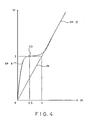
- Figure 4 shows a cutting with two axes according to prior art.
- the X-axis has a relatively weak mechanical rigidity and the Y-axis has a relatively strong mechanical rigidity, and with these control axes, when the X-axis is moved by 0.100 mm, the Y-axis is moved by 0.200 mm.
- the present invention has been made in view of the aforesaid drawbacks, and an object thereof is to provide a method of correcting a machine position change in which an abrupt machining error caused by a difference of the mechanical rigidities of machine parts at which control axes are provided can be suppressed.
- the present invention provides a method of correcting a change of position of a machine tool having at least two control axes, characterized in that a correction pulse is added to distribution pulses for individual axes, such that the ratio of values of error registers associated with the respective axes is equal to the ratio of the distribution pulses for the respective axes.
- the values of the error registers of the respective axes represent values by which the movement has not been achieved by the distribution pulses. Therefore, when the mechanical rigidities of all axes are the same, the ratio of the distribution pulses for the respective axes is usually equal to the ratio of the values of the error registers. Nevertheless, if an error occurs due to a difference in the mechanical rigidities, the ratio of the values of the error registers does not coincide with the ratio of the distribution pulses for the respective axes.
- a correction pulse is added to the distribution pulses for the respective axes so that the ratio of the values of the error registers associated with the respective axes is equal to the ratio of the distribution pulses for the respective axes, and the axes are controlled in accordance with the resulting output pulses. Accordingly, an abrupt machining error which may otherwise occur at the beginning or just before the end of machining or when machining a corner of a workpiece, can be suppressed.
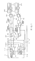
- Figure 1 is a block diagram showing a method of correcting a machine position change according to the present invention.
- a numerical control unit 1 is provided with a pulse distribution means 11 and a position correction means 12.
- the pulse distribution means 11 controls servomotors 5X and 5Y. Specifically, the means 11 receives a command based on a machining program from a processor (not shown), carries out an interpolative operation after subjecting the command to an acceleration/deceleration control, and outputs command pulses Xp1 and Yp1 to operators 12X and 12Y to control the servomotors 5X and 5Y associated with the X-and Y-axes, respectively.
- the pulse distribution means 11 calculates the ratio R1 of the command pulse Xp1 to the pulse Yp1 and outputs a signal R1, representing the result, to the position correction means 12.
- the position correction means 12 is supplied with error amount a Xe and Ye from error registers 3X and 3Y, and the signal R1 from the pulse distribution means 11. Thereafter, the position correction means 12 calculates the ratio R2 between the error amounts Xe and Ye, compares the result with the ratio R1 of the command pulse Xp1 to the pulse Yp1, output from the pulse distribution means 11, and supplies a correction pulse Xcp or Ycp to the operator 12X or 12Y, to make the two ratios equal.
- the operators 12X and 12Y output command pulses Xp2 and Yp2, which are obtained by adding the command pulses Xp1 and Yp1 to the correction pulses Xcp and Ycp from the position correction means 12, to operators 2X and 2Y.
- the operators 2X and 2Y output values obtained by subtracting position feedback pulses Xfp and Yfp of the servomotors 5X and 5Y from the command pulses Xp2 and Yp2, i.e., pulses Xp3 and Yp3 corresponding to the error amounts, to the error registers 3X and 3Y.
- the error registers 3X and 3Y store the numbers of the pulses Xp3 and Yp3 corresponding to the error amounts and output voltages corresponding thereto to amplifiers 4X and 4Y.
- the amplifiers 4X and 4Y amplify output voltages from the error registers 3X and 3Y and drive the servomotors 5X and 5Y.
- the servomotors 5X and 5Y each including a pulse coder, feed the outputs of the respective pulse coders back to the operators 2X and 2Y as the position feedback pulses Xfp and Yfp.
- the servomotors 5X and 5Y are coupled to ball screws 7X and 7Y integral with tables, and therefore, an X-axis table 6X and a Y-axis table 6Y are moved in accordance with the operation of the servomotors 5X and 5Y.
- the tables 6X and 6Y are shown as separate elements, but in practice they constitute one table. Also in the figure, a spindle control circuit, spindle amplifier and spindle motor for controlling a spindle and the like, are omitted.
- Figure 2 is a flowchart showing the position correction method according to the present embodiment
- Fig. 3 is a diagram showing a state of a cutting interpolation with two axes according to the present embodiment, which corresponds to Fig. 4.
- numerical values following the letter S show the step numbers.
- a machining error such as that shown in Fig. 4 is suppressed as shown in Fig. 3, in which the error is minimized and the curve B1 is converted to the straight line B2, and thus a more precise linear cutting can be effected. That is, in the present embodiment, the process is repeated in such a manner that the values of the error registers 3X and 3Y are monitored and the correction pulse Xcp or Ycp is added to the output pulse when the ratio R2 of the values of the error registers becomes different from the ratio R1 (1:2), whereby the ratio R2 is made equal to the ratio R1 (1:2). Accordingly, an abrupt machining error such as the one shown in Fig. 4 is inhibited and a cutting as shown in Fig. 3 can be carried out.
- an abrupt machining error caused by a difference in the mechanical rigidities of the control axes can be alleviated.
Landscapes
- Engineering & Computer Science (AREA)
- Human Computer Interaction (AREA)
- Manufacturing & Machinery (AREA)
- Physics & Mathematics (AREA)
- General Physics & Mathematics (AREA)
- Automation & Control Theory (AREA)
- Numerical Control (AREA)
Applications Claiming Priority (2)
| Application Number | Priority Date | Filing Date | Title |
|---|---|---|---|
| JP29856789A JPH03157703A (ja) | 1989-11-16 | 1989-11-16 | 機械位置変動の位置補正方式 |
| JP298567/89 | 1989-11-16 |
Publications (1)
| Publication Number | Publication Date |
|---|---|
| EP0453572A1 true EP0453572A1 (de) | 1991-10-30 |
Family
ID=17861419
Family Applications (1)
| Application Number | Title | Priority Date | Filing Date |
|---|---|---|---|
| EP19900916064 Withdrawn EP0453572A1 (de) | 1989-11-16 | 1990-11-02 | Verfahren zum korrigieren der lageschwankung einer maschine |
Country Status (3)
| Country | Link |
|---|---|
| EP (1) | EP0453572A1 (de) |
| JP (1) | JPH03157703A (de) |
| WO (1) | WO1991007704A1 (de) |
Family Cites Families (3)
| Publication number | Priority date | Publication date | Assignee | Title |
|---|---|---|---|---|
| JPS6123213A (ja) * | 1984-07-10 | 1986-01-31 | Kobe Steel Ltd | ロボツトの制御装置 |
| JPS6428705A (en) * | 1987-07-24 | 1989-01-31 | Yaskawa Denki Seisakusho Kk | Command generating system |
| JPH01185705A (ja) * | 1988-01-20 | 1989-07-25 | Yaskawa Electric Mfg Co Ltd | サーボシステム |
-
1989
- 1989-11-16 JP JP29856789A patent/JPH03157703A/ja active Pending
-
1990
- 1990-11-02 WO PCT/JP1990/001430 patent/WO1991007704A1/ja not_active Ceased
- 1990-11-02 EP EP19900916064 patent/EP0453572A1/de not_active Withdrawn
Non-Patent Citations (1)
| Title |
|---|
| See references of WO9107704A1 * |
Also Published As
| Publication number | Publication date |
|---|---|
| WO1991007704A1 (fr) | 1991-05-30 |
| JPH03157703A (ja) | 1991-07-05 |
Similar Documents
| Publication | Publication Date | Title |
|---|---|---|
| US5210478A (en) | Method of correcting machine position change | |
| US6097168A (en) | Position control apparatus and method of the same, numerical control program preparation apparatus and method of the same, and methods of controlling numerical control machine tool | |
| US4617635A (en) | Numerical control machining system | |
| US5177421A (en) | Method of correcting machine position change | |
| KR100820438B1 (ko) | 수치 제어 장치 | |
| CA1334864C (en) | Method and system for controlling a machine tool such as a turning machine | |
| EP0487738B1 (de) | System zur berichtung der werkzeugverbiegungsgrösse | |
| EP0453572A1 (de) | Verfahren zum korrigieren der lageschwankung einer maschine | |
| JP4398070B2 (ja) | 工作機械の数値制御装置および溝加工方法 | |
| EP0394469A1 (de) | Numerische steuerung | |
| US6681146B2 (en) | Method and apparatus for controlling driver mechanism in NC machine tool | |
| JPH06190683A (ja) | 工具の移動経路生成方法 | |
| JPH06246589A (ja) | 機内測定による非円形ワークの誤差補正方法 | |
| JP4036502B2 (ja) | Ncプログラム作成方法、作成装置及びnc工作機械の制御方法 | |
| EP0404947A1 (de) | Numerische steuerung | |
| JPH02156308A (ja) | 数値制御装置 | |
| JPH04117506A (ja) | 加速度制御による位置補正方式 | |
| JP2926524B2 (ja) | 試切削機能を有する数値制御装置 | |
| JPH0452708A (ja) | 誤動作チェック方式 | |
| JPH04176516A (ja) | ワイヤ放電加工におけるセカンドカット加工方法及びセカンドカット加工制御装置 | |
| JPH04331041A (ja) | 工作機械における刃先位置補正装置 | |
| JPH08150540A (ja) | 工作機械の干渉防止装置 | |
| KR0168071B1 (ko) | 공구직경에 따른 이동경로 보정방법 | |
| KR0168072B1 (ko) | 공구직경에 따른 이동경로 보정방법 | |
| KR0168069B1 (ko) | 공구직경에 따른 이동경로 보정방법 |
Legal Events
| Date | Code | Title | Description |
|---|---|---|---|
| PUAI | Public reference made under article 153(3) epc to a published international application that has entered the european phase |
Free format text: ORIGINAL CODE: 0009012 |
|
| 17P | Request for examination filed |
Effective date: 19910802 |
|
| AK | Designated contracting states |
Kind code of ref document: A1 Designated state(s): CH DE FR GB IT LI |
|
| 18W | Application withdrawn |
Withdrawal date: 19921201 |
|
| STAA | Information on the status of an ep patent application or granted ep patent |
Free format text: STATUS: THE APPLICATION HAS BEEN WITHDRAWN |
|
| R18W | Application withdrawn (corrected) |
Effective date: 19921201 |