EP0453428B1 - Verfahren zur Herstellung von Sinterkarbidkörpern für Werkzeuge und Verschleissteile - Google Patents
Verfahren zur Herstellung von Sinterkarbidkörpern für Werkzeuge und Verschleissteile Download PDFInfo
- Publication number
- EP0453428B1 EP0453428B1 EP91850100A EP91850100A EP0453428B1 EP 0453428 B1 EP0453428 B1 EP 0453428B1 EP 91850100 A EP91850100 A EP 91850100A EP 91850100 A EP91850100 A EP 91850100A EP 0453428 B1 EP0453428 B1 EP 0453428B1
- Authority
- EP
- European Patent Office
- Prior art keywords
- cemented carbide
- bodies
- sintering
- tools
- wear parts
- Prior art date
- Legal status (The legal status is an assumption and is not a legal conclusion. Google has not performed a legal analysis and makes no representation as to the accuracy of the status listed.)
- Expired - Lifetime
Links
- 238000004519 manufacturing process Methods 0.000 title claims abstract description 10
- 238000000034 method Methods 0.000 claims abstract description 13
- 239000011435 rock Substances 0.000 claims abstract description 8
- 238000005553 drilling Methods 0.000 claims abstract description 7
- 238000005245 sintering Methods 0.000 claims description 19
- 238000003826 uniaxial pressing Methods 0.000 claims description 4
- 239000000203 mixture Substances 0.000 abstract description 4
- 238000003825 pressing Methods 0.000 description 11
- 239000002184 metal Substances 0.000 description 7
- 229910052751 metal Inorganic materials 0.000 description 7
- 229910017052 cobalt Inorganic materials 0.000 description 6
- 239000010941 cobalt Substances 0.000 description 6
- GUTLYIVDDKVIGB-UHFFFAOYSA-N cobalt atom Chemical compound [Co] GUTLYIVDDKVIGB-UHFFFAOYSA-N 0.000 description 6
- 238000005056 compaction Methods 0.000 description 5
- 239000000463 material Substances 0.000 description 5
- 238000005219 brazing Methods 0.000 description 4
- 238000005520 cutting process Methods 0.000 description 4
- 238000003754 machining Methods 0.000 description 4
- 230000007704 transition Effects 0.000 description 4
- 238000005336 cracking Methods 0.000 description 3
- 241000446313 Lamella Species 0.000 description 2
- 239000002826 coolant Substances 0.000 description 2
- 229910000831 Steel Inorganic materials 0.000 description 1
- 239000011230 binding agent Substances 0.000 description 1
- 239000000919 ceramic Substances 0.000 description 1
- 238000007796 conventional method Methods 0.000 description 1
- 230000007797 corrosion Effects 0.000 description 1
- 238000005260 corrosion Methods 0.000 description 1
- 230000003247 decreasing effect Effects 0.000 description 1
- 230000007547 defect Effects 0.000 description 1
- 239000012467 final product Substances 0.000 description 1
- 229910052500 inorganic mineral Inorganic materials 0.000 description 1
- 238000007689 inspection Methods 0.000 description 1
- 238000003801 milling Methods 0.000 description 1
- 239000011707 mineral Substances 0.000 description 1
- 239000000843 powder Substances 0.000 description 1
- 238000002360 preparation method Methods 0.000 description 1
- 239000007787 solid Substances 0.000 description 1
- 238000010561 standard procedure Methods 0.000 description 1
- 239000010959 steel Substances 0.000 description 1
Images


Classifications
-
- E—FIXED CONSTRUCTIONS
- E21—EARTH OR ROCK DRILLING; MINING
- E21B—EARTH OR ROCK DRILLING; OBTAINING OIL, GAS, WATER, SOLUBLE OR MELTABLE MATERIALS OR A SLURRY OF MINERALS FROM WELLS
- E21B10/00—Drill bits
- E21B10/46—Drill bits characterised by wear resisting parts, e.g. diamond inserts
- E21B10/56—Button-type inserts
-
- B—PERFORMING OPERATIONS; TRANSPORTING
- B22—CASTING; POWDER METALLURGY
- B22F—WORKING METALLIC POWDER; MANUFACTURE OF ARTICLES FROM METALLIC POWDER; MAKING METALLIC POWDER; APPARATUS OR DEVICES SPECIALLY ADAPTED FOR METALLIC POWDER
- B22F7/00—Manufacture of composite layers, workpieces, or articles, comprising metallic powder, by sintering the powder, with or without compacting wherein at least one part is obtained by sintering or compression
- B22F7/06—Manufacture of composite layers, workpieces, or articles, comprising metallic powder, by sintering the powder, with or without compacting wherein at least one part is obtained by sintering or compression of composite workpieces or articles from parts, e.g. to form tipped tools
- B22F7/062—Manufacture of composite layers, workpieces, or articles, comprising metallic powder, by sintering the powder, with or without compacting wherein at least one part is obtained by sintering or compression of composite workpieces or articles from parts, e.g. to form tipped tools involving the connection or repairing of preformed parts
-
- E—FIXED CONSTRUCTIONS
- E21—EARTH OR ROCK DRILLING; MINING
- E21B—EARTH OR ROCK DRILLING; OBTAINING OIL, GAS, WATER, SOLUBLE OR MELTABLE MATERIALS OR A SLURRY OF MINERALS FROM WELLS
- E21B10/00—Drill bits
- E21B10/46—Drill bits characterised by wear resisting parts, e.g. diamond inserts
- E21B10/58—Chisel-type inserts
-
- Y—GENERAL TAGGING OF NEW TECHNOLOGICAL DEVELOPMENTS; GENERAL TAGGING OF CROSS-SECTIONAL TECHNOLOGIES SPANNING OVER SEVERAL SECTIONS OF THE IPC; TECHNICAL SUBJECTS COVERED BY FORMER USPC CROSS-REFERENCE ART COLLECTIONS [XRACs] AND DIGESTS
- Y10—TECHNICAL SUBJECTS COVERED BY FORMER USPC
- Y10S—TECHNICAL SUBJECTS COVERED BY FORMER USPC CROSS-REFERENCE ART COLLECTIONS [XRACs] AND DIGESTS
- Y10S76/00—Metal tools and implements, making
- Y10S76/11—Tungsten and tungsten carbide
-
- Y—GENERAL TAGGING OF NEW TECHNOLOGICAL DEVELOPMENTS; GENERAL TAGGING OF CROSS-SECTIONAL TECHNOLOGIES SPANNING OVER SEVERAL SECTIONS OF THE IPC; TECHNICAL SUBJECTS COVERED BY FORMER USPC CROSS-REFERENCE ART COLLECTIONS [XRACs] AND DIGESTS
- Y10—TECHNICAL SUBJECTS COVERED BY FORMER USPC
- Y10T—TECHNICAL SUBJECTS COVERED BY FORMER US CLASSIFICATION
- Y10T407/00—Cutters, for shaping
- Y10T407/27—Cutters, for shaping comprising tool of specific chemical composition
Definitions
- the present invention relates to a method of making a cemented carbide body for rock and metal drilling tools and wear parts.
- the method is particularly useful for preparation of a cemented carbide body which for some reason, e.g. the outer shape, cannot directly be pressed to final form by uniaxial pressing.
- Cemented carbide bodies are usually made by powder metallurgical methods: pressing and sintering.
- the desired form of the sintered body has to be obtained as far as possible before sintering because machining of the sintered body is expensive and in most cases even not profitable. Machining to desired shape is therefore done, if nessesary, in as pressed and/or presintered condition after which the body is finally sintered. Even this is an expensive operation.
- the body is generally given such a form that it can be directly pressed by uniaxial pressing. That means, however, great limitations. For example, can be mentioned the necessity of positive clearances in the pressing direction, a critical height to width ratio, no abrupt transitions from small to large diameter etc.
- cemented carbide body is usually a compromise between what is possible to produce by uniaxial pressing and the really desired one.
- bodies with complicated geometry can be made by use of a collapsible tool in which the die after the pressing is divided in order to expose the compact.
- Such tools are expensive, however, and sensitive to the high compacting pressures being used in the production of cemented carbide.
- the above-mentioned method is suitable to use in the production of bodies in large series e.g. cutting inserts and buttons for rock drilling tools which can carry the costs of producing the necessary pressing tools.
- bodies in large series such as wear parts one usually starts from a simpler body which then is machined to desired shape. Said machining is expensive with often great material loss because large volumes usually have to be removed.
- the final form is a compromise between desired form and what is possible and reasonable, technically as well as economically.
- cemented carbide bodies in a relatively simple way by pressing partial bodies with simple geometry possible to compact directly after which said partial bodies are sintered together to a body with desired, often complex geometry.
- SE pat. appl. 8803769-2 which relates to a double-positive cutting insert for chipforming machining.
- the method can also be used for making other bodies of cemented carbide e.g. rods or blanks for drills and end mills, rock drilling tools and wear parts.
- the body can also be made of other hard materials e.g. ceramics or carbonitride-based materials so called cermets.
- the method according to the invention makes it possible in certain cases to produce cemented carbide bodies simpler and cheaper and with better performance.
- cemented carbide bodies according to the invention are shown in Figs. 1-6. It is obvious for a person skilled in the art how the method according to the invention shall be applied also to other embodiments of hard metal bodies.
- the method can also be used for making cemented carbide consisting of two or more grades being different with respect to composition and/or grain size e.g. a tough core with a wear resistant cover and vice versa.
- a tough core with a wear resistant cover In the production of such hard metal it is important that the shrinkage is similar in both bodies so that cracking does not occur.
- This kind of hard metal is particularly suitable to use when brazing parts because a cobalt-rich, tough cemented carbide is easier to braze than a cobalt-poor. This depends upon the difference in thermal expansion coefficient. Steel has high thermal expansion and cemented carbide has low. Cemented carbide with high cobalt content has a higher expansion than cemented carbide with low content of cobalt. Cemented carbide with low content of cobalt is difficult to braze because of increased risks for cracking of the parts due to high brazing stresses and brittle material. In this way an optimal grade for the application can be used without taking any particular consideration to the brazeability.
- a so called gas pressure sintering of the body is used. It means that the body is first sintered under normal pressure. When closed porosity has been obtained the pressure is increased and final sintering is performed under increased pressure. In this way an increased strength in the body is obtained and the joint will easier sinter to full density.
- the ring a was provided with totally four protrusions and the ring b with four corresponding grooves. At the sintering the ring a was placed upon the ring b so that the projections and the grooves were fit together and locked the relative position of the rings. The sintering was performed in vacuum at 1450 °C and 2 h sintering time.
- the material was a corrosion resistant cemented carbide grade having a binder phase of type Ni-Cr-Mo and a hardness of 1520 HV3. Said grade is regarded as difficult to press.
- rings were manufactured according to conventional method i.e. with direct-pressing of the whole part. At the same time 1000 rings according to the invention were sintered. The rings were examined with respect to cracks with the following results: Conventionally made rings: 738 free of cracks 262 with cracks Rings according to the inv.: 1000 free of cracks
- Buttons for raise boring according to Fig. 2 were manufactured, B, (500 pieces) according to the invention, A, (500 pieces) by conventional direct-pressing technique.
- the cemented carbide had the composition 8 % Co, 92 % WC and a hardness of 1250 HV3.
- the buttons according to the invention consisted of two separately pressed parts, a and b, according to the figure. At the sintering the chisel part was placed on the cylindrical part. The fixing was done by two protrusions in the chisel part and corresponding grooves in the cylindrical part. An ocular examination gave the following results: With cracks Without cracks Conv. made buttons 86 414 Acc. to the invent. 0 500
- buttons regarded as free of cracks might have had cracks. For that reason twelve buttons per variant were examined metallographically. All buttons according to the invention were free of cracks, however. The joint between the two parts sintered together could not be observed in 1500 X magnification except in connection to the protrusions/grooves. Eight of the conventionally manufactured buttons showed cracks 0.3-0.6 mm deep. Four of these had been detected at the ocular inspection.
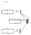
- a cemented carbide body for mineral cutting and road planing according to Fig. 3 with 11 % Co and a grain size of 4 ⁇ m (1130 HV3) was directly pressed and sintered according to standard procedure, A.
- the degree of compaction will be very high at the wall of the die and press-cracks of up to 1 mm could be observed in the collar after the sintering. If the pressing is performed with lower compaction pressure the risks for cracks are decreased but the degree of compaction in the centre of the body will then be so low that an unacceptably high porosity level is obtained.
- a cylindrical body was made according to the invention like an ordinary rock tool button according to a in Fig. 3 and an outer ring, b.
- the button was placed within the ring and the whole was sintered.
- the compaction pressure so that the ring shrunk somewhat more than the button during the sintering a body without a visible joint was obtained, B.
- Bodies according to the preceding example were manufactured by pressing and sintering together a short button, a, and a bottom disk, b, Fig 4.
- the button had a protrusion in the bottom and the disk had a corresponding groove by which the bodies were fixed relatively to each other during the sintering.
- the reason for the improved result of the body according to the invention is the combination of hard and wear-resistant tip on a tougher bottom-part which can better handle the brazing stresses.
- Chisel inserts for rock drilling tool bits are usually brazed in a milled groove in the bit-end of a drill rod.
- the inserts consist conventionally of grades with 8-11 % Co and 2.5-5 ⁇ m grain size.
- Chisel inserts were manufactured according to the invention from three together-sintered lamella at which the intermediate lamella has a low content of cobalt while the two surrounding ones have a higher cobalt content.
- Blanks for solid cemented carbide drills (diam. 6mm, length 700 mm) with internal coolant channels were manufactured by sintering together three pieces 1,2,3 according to Fig. 6. The individual pieces were tool pressed in an automatic mechanical press. The outer parts contained grooves to form the helicant coolant channels in the final product and means for securing the relative positions of the pieces during sintering.
Landscapes
- Engineering & Computer Science (AREA)
- Geology (AREA)
- Life Sciences & Earth Sciences (AREA)
- Mining & Mineral Resources (AREA)
- Mechanical Engineering (AREA)
- General Life Sciences & Earth Sciences (AREA)
- Fluid Mechanics (AREA)
- Environmental & Geological Engineering (AREA)
- Physics & Mathematics (AREA)
- Geochemistry & Mineralogy (AREA)
- Manufacturing & Machinery (AREA)
- Composite Materials (AREA)
- Chemical & Material Sciences (AREA)
- Materials Engineering (AREA)
- Powder Metallurgy (AREA)
- Earth Drilling (AREA)
- Carbon And Carbon Compounds (AREA)
- Cutting Tools, Boring Holders, And Turrets (AREA)
- Ceramic Products (AREA)
Claims (2)
- Verfahren zur Herstellung eines Sinterkarbidkörpers mit komplizierter Geometrie für Gesteinsbohrwerkzeuge und Verschleißteile, bei dem Teilkörper mit einfacher Geometrie verdichtet, aufeinandergelegt, wobei Verbindungsstellen im wesentlichen horizontal liegen, und dann zusammengesintert werden, dadurch gekennzeichnet, daß das Sintern bei normalem Druck begonnen wird, welcher gesteigert wird, wenn geschlossene Porosität erhalten wurde.
- Verfahren nach Anspruch 1, dadurch gekennzeichnet, daß der Körper eine solche Form hat, daß er nicht direkt durch uniaxiales Pressen zu einer Endform gepreßt werden kann.
Priority Applications (1)
| Application Number | Priority Date | Filing Date | Title |
|---|---|---|---|
| EP96109560A EP0733424A3 (de) | 1990-04-20 | 1991-04-18 | Verfahren zur Herstellung von Sinterkarbidkörpern für Werkzeuge und Verschleissteile |
Applications Claiming Priority (2)
| Application Number | Priority Date | Filing Date | Title |
|---|---|---|---|
| SE9001409A SE9001409D0 (sv) | 1990-04-20 | 1990-04-20 | Metod foer framstaellning av haardmetallkropp foer bergborrverktyg och slitdelar |
| SE9001409 | 1990-04-20 |
Related Child Applications (1)
| Application Number | Title | Priority Date | Filing Date |
|---|---|---|---|
| EP96109560.1 Division-Into | 1991-04-18 |
Publications (2)
| Publication Number | Publication Date |
|---|---|
| EP0453428A1 EP0453428A1 (de) | 1991-10-23 |
| EP0453428B1 true EP0453428B1 (de) | 1997-01-02 |
Family
ID=20379225
Family Applications (2)
| Application Number | Title | Priority Date | Filing Date |
|---|---|---|---|
| EP96109560A Withdrawn EP0733424A3 (de) | 1990-04-20 | 1991-04-18 | Verfahren zur Herstellung von Sinterkarbidkörpern für Werkzeuge und Verschleissteile |
| EP91850100A Expired - Lifetime EP0453428B1 (de) | 1990-04-20 | 1991-04-18 | Verfahren zur Herstellung von Sinterkarbidkörpern für Werkzeuge und Verschleissteile |
Family Applications Before (1)
| Application Number | Title | Priority Date | Filing Date |
|---|---|---|---|
| EP96109560A Withdrawn EP0733424A3 (de) | 1990-04-20 | 1991-04-18 | Verfahren zur Herstellung von Sinterkarbidkörpern für Werkzeuge und Verschleissteile |
Country Status (6)
| Country | Link |
|---|---|
| US (1) | US5333520A (de) |
| EP (2) | EP0733424A3 (de) |
| JP (1) | JPH04228505A (de) |
| AT (1) | ATE146999T1 (de) |
| DE (1) | DE69123872T2 (de) |
| SE (1) | SE9001409D0 (de) |
Cited By (5)
| Publication number | Priority date | Publication date | Assignee | Title |
|---|---|---|---|---|
| DE10305205A1 (de) * | 2003-02-07 | 2004-08-26 | Betek Bergbau- Und Hartmetalltechnik Karl-Heinz Simon Gmbh & Co. Kg | Schaftmeißel |
| US8201610B2 (en) | 2009-06-05 | 2012-06-19 | Baker Hughes Incorporated | Methods for manufacturing downhole tools and downhole tool parts |
| US8388723B2 (en) | 2005-09-09 | 2013-03-05 | Baker Hughes Incorporated | Abrasive wear-resistant materials, methods for applying such materials to earth-boring tools, and methods of securing a cutting element to an earth-boring tool using such materials |
| US9200485B2 (en) | 2005-09-09 | 2015-12-01 | Baker Hughes Incorporated | Methods for applying abrasive wear-resistant materials to a surface of a drill bit |
| US9506297B2 (en) | 2005-09-09 | 2016-11-29 | Baker Hughes Incorporated | Abrasive wear-resistant materials and earth-boring tools comprising such materials |
Families Citing this family (74)
| Publication number | Priority date | Publication date | Assignee | Title |
|---|---|---|---|---|
| SE9103065D0 (sv) * | 1991-10-21 | 1991-10-21 | Sandvik Ab | Metod foer framstaellning av keramisk kropp |
| SE505526C2 (sv) * | 1994-11-08 | 1997-09-15 | Sandvik Ab | Avsticksskär |
| US5762843A (en) * | 1994-12-23 | 1998-06-09 | Kennametal Inc. | Method of making composite cermet articles |
| US5541006A (en) * | 1994-12-23 | 1996-07-30 | Kennametal Inc. | Method of making composite cermet articles and the articles |
| US5679445A (en) * | 1994-12-23 | 1997-10-21 | Kennametal Inc. | Composite cermet articles and method of making |
| US5594931A (en) * | 1995-05-09 | 1997-01-14 | Newcomer Products, Inc. | Layered composite carbide product and method of manufacture |
| US5623723A (en) * | 1995-08-11 | 1997-04-22 | Greenfield; Mark S. | Hard composite and method of making the same |
| US6183687B1 (en) | 1995-08-11 | 2001-02-06 | Kennametal Inc. | Hard composite and method of making the same |
| SE518810C2 (sv) * | 1996-07-19 | 2002-11-26 | Sandvik Ab | Hårdmetallkropp med förbättrade högtemperatur- och termomekaniska egenskaper |
| AT1770U1 (de) * | 1996-12-04 | 1997-11-25 | Miba Sintermetall Ag | Verfahren zum herstellen eines sinterformkörpers, insbesondere eines zahnriemen- oder kettenrades |
| US6197431B1 (en) * | 1997-06-20 | 2001-03-06 | Siemens Westinghouse Power Corporation | Composite material machining tools |
| US6315945B1 (en) | 1997-07-16 | 2001-11-13 | The Dow Chemical Company | Method to form dense complex shaped articles |
| GB9720059D0 (en) * | 1997-09-19 | 1997-11-19 | Isis Innovation | Method of bonding |
| DE19912721C1 (de) * | 1999-03-20 | 2000-08-10 | Simon Karl Gmbh & Co Kg | Verfahren zum Herstellen einer Fräslamelle und nach dem Verfahren hergestellte Fräslamelle |
| US6076754A (en) * | 1999-04-16 | 2000-06-20 | Littlef Ord Day, Incorporated | Mixer apparatus with improved chopper assembly |
| US6511265B1 (en) * | 1999-12-14 | 2003-01-28 | Ati Properties, Inc. | Composite rotary tool and tool fabrication method |
| DE19962232B4 (de) * | 1999-12-22 | 2006-05-04 | Vacuumschmelze Gmbh | Verfahren zur Herstellung stabförmiger Dauermagnete |
| US6571889B2 (en) | 2000-05-01 | 2003-06-03 | Smith International, Inc. | Rotary cone bit with functionally-engineered composite inserts |
| AT4665U1 (de) * | 2000-07-14 | 2001-10-25 | Plansee Tizit Ag | Verfahren zum pressen einer schneidplatte |
| US6908688B1 (en) | 2000-08-04 | 2005-06-21 | Kennametal Inc. | Graded composite hardmetals |
| US20040157066A1 (en) * | 2003-02-07 | 2004-08-12 | Arzoumanidis G. Alexis | Method of applying a hardcoating typically provided on downhole tools, and a system and apparatus having such a hardcoating |
| US7384443B2 (en) | 2003-12-12 | 2008-06-10 | Tdy Industries, Inc. | Hybrid cemented carbide composites |
| US9428822B2 (en) | 2004-04-28 | 2016-08-30 | Baker Hughes Incorporated | Earth-boring tools and components thereof including material having hard phase in a metallic binder, and metallic binder compositions for use in forming such tools and components |
| US20050211475A1 (en) | 2004-04-28 | 2005-09-29 | Mirchandani Prakash K | Earth-boring bits |
| JP2006046540A (ja) * | 2004-08-05 | 2006-02-16 | Matsushita Electric Ind Co Ltd | 動圧流体軸受装置 |
| US7513320B2 (en) | 2004-12-16 | 2009-04-07 | Tdy Industries, Inc. | Cemented carbide inserts for earth-boring bits |
| US8637127B2 (en) | 2005-06-27 | 2014-01-28 | Kennametal Inc. | Composite article with coolant channels and tool fabrication method |
| US7687156B2 (en) | 2005-08-18 | 2010-03-30 | Tdy Industries, Inc. | Composite cutting inserts and methods of making the same |
| US7776256B2 (en) | 2005-11-10 | 2010-08-17 | Baker Huges Incorporated | Earth-boring rotary drill bits and methods of manufacturing earth-boring rotary drill bits having particle-matrix composite bit bodies |
| US8002052B2 (en) | 2005-09-09 | 2011-08-23 | Baker Hughes Incorporated | Particle-matrix composite drill bits with hardfacing |
| US7913779B2 (en) | 2005-11-10 | 2011-03-29 | Baker Hughes Incorporated | Earth-boring rotary drill bits including bit bodies having boron carbide particles in aluminum or aluminum-based alloy matrix materials, and methods for forming such bits |
| US7784567B2 (en) | 2005-11-10 | 2010-08-31 | Baker Hughes Incorporated | Earth-boring rotary drill bits including bit bodies comprising reinforced titanium or titanium-based alloy matrix materials, and methods for forming such bits |
| US7802495B2 (en) | 2005-11-10 | 2010-09-28 | Baker Hughes Incorporated | Methods of forming earth-boring rotary drill bits |
| US8770324B2 (en) | 2008-06-10 | 2014-07-08 | Baker Hughes Incorporated | Earth-boring tools including sinterbonded components and partially formed tools configured to be sinterbonded |
| US7807099B2 (en) | 2005-11-10 | 2010-10-05 | Baker Hughes Incorporated | Method for forming earth-boring tools comprising silicon carbide composite materials |
| RU2432445C2 (ru) | 2006-04-27 | 2011-10-27 | Ти Ди Уай Индастриз, Инк. | Модульное буровое долото с неподвижными режущими элементами, корпус данного модульного бурового долота и способы их изготовления |
| CA2662966C (en) | 2006-08-30 | 2012-11-13 | Baker Hughes Incorporated | Methods for applying wear-resistant material to exterior surfaces of earth-boring tools and resulting structures |
| EP2078101A2 (de) | 2006-10-25 | 2009-07-15 | TDY Industries, Inc. | Artikel mit erhöhter widerstandsfähigkeit gegenüber thermischem cracken |
| US8272295B2 (en) | 2006-12-07 | 2012-09-25 | Baker Hughes Incorporated | Displacement members and intermediate structures for use in forming at least a portion of bit bodies of earth-boring rotary drill bits |
| US7775287B2 (en) | 2006-12-12 | 2010-08-17 | Baker Hughes Incorporated | Methods of attaching a shank to a body of an earth-boring drilling tool, and tools formed by such methods |
| US7841259B2 (en) | 2006-12-27 | 2010-11-30 | Baker Hughes Incorporated | Methods of forming bit bodies |
| US8454274B2 (en) | 2007-01-18 | 2013-06-04 | Kennametal Inc. | Cutting inserts |
| US9101985B2 (en) | 2007-01-18 | 2015-08-11 | Kennametal Inc. | Cutting insert assembly and components thereof |
| US7963729B2 (en) | 2007-01-18 | 2011-06-21 | Kennametal Inc. | Milling cutter and milling insert with coolant delivery |
| US8439608B2 (en) * | 2007-01-18 | 2013-05-14 | Kennametal Inc. | Shim for a cutting insert and cutting insert-shim assembly with internal coolant delivery |
| US7883299B2 (en) * | 2007-01-18 | 2011-02-08 | Kennametal Inc. | Metal cutting system for effective coolant delivery |
| US8328471B2 (en) | 2007-01-18 | 2012-12-11 | Kennametal Inc. | Cutting insert with internal coolant delivery and cutting assembly using the same |
| US8727673B2 (en) | 2007-01-18 | 2014-05-20 | Kennametal Inc. | Cutting insert with internal coolant delivery and surface feature for enhanced coolant flow |
| US20080175679A1 (en) * | 2007-01-18 | 2008-07-24 | Paul Dehnhardt Prichard | Milling cutter and milling insert with core and coolant delivery |
| US7625157B2 (en) | 2007-01-18 | 2009-12-01 | Kennametal Inc. | Milling cutter and milling insert with coolant delivery |
| US8512882B2 (en) | 2007-02-19 | 2013-08-20 | TDY Industries, LLC | Carbide cutting insert |
| US7846551B2 (en) | 2007-03-16 | 2010-12-07 | Tdy Industries, Inc. | Composite articles |
| EP2653580B1 (de) | 2008-06-02 | 2014-08-20 | Kennametal Inc. | Zementierte carbidmetallische Legierungsverbindungen |
| US8790439B2 (en) | 2008-06-02 | 2014-07-29 | Kennametal Inc. | Composite sintered powder metal articles |
| US7703556B2 (en) | 2008-06-04 | 2010-04-27 | Baker Hughes Incorporated | Methods of attaching a shank to a body of an earth-boring tool including a load-bearing joint and tools formed by such methods |
| US8261632B2 (en) | 2008-07-09 | 2012-09-11 | Baker Hughes Incorporated | Methods of forming earth-boring drill bits |
| US8025112B2 (en) | 2008-08-22 | 2011-09-27 | Tdy Industries, Inc. | Earth-boring bits and other parts including cemented carbide |
| US8322465B2 (en) | 2008-08-22 | 2012-12-04 | TDY Industries, LLC | Earth-boring bit parts including hybrid cemented carbides and methods of making the same |
| US7955032B2 (en) | 2009-01-06 | 2011-06-07 | Kennametal Inc. | Cutting insert with coolant delivery and method of making the cutting insert |
| US8272816B2 (en) | 2009-05-12 | 2012-09-25 | TDY Industries, LLC | Composite cemented carbide rotary cutting tools and rotary cutting tool blanks |
| US8308096B2 (en) | 2009-07-14 | 2012-11-13 | TDY Industries, LLC | Reinforced roll and method of making same |
| US8440314B2 (en) | 2009-08-25 | 2013-05-14 | TDY Industries, LLC | Coated cutting tools having a platinum group metal concentration gradient and related processes |
| US9643236B2 (en) | 2009-11-11 | 2017-05-09 | Landis Solutions Llc | Thread rolling die and method of making same |
| RU2012155101A (ru) | 2010-05-20 | 2014-06-27 | Бейкер Хьюз Инкорпорейтед | Способы формирования по меньшей мере части бурильного инструмента |
| EP2571647A4 (de) | 2010-05-20 | 2017-04-12 | Baker Hughes Incorporated | Verfahren zur formung mindestens eines teils eines erdbohrwerkzeugs und in diesen verfahren geformte artikel |
| WO2011146760A2 (en) | 2010-05-20 | 2011-11-24 | Baker Hughes Incorporated | Methods of forming at least a portion of earth-boring tools, and articles formed by such methods |
| US8734062B2 (en) | 2010-09-02 | 2014-05-27 | Kennametal Inc. | Cutting insert assembly and components thereof |
| US8827599B2 (en) | 2010-09-02 | 2014-09-09 | Kennametal Inc. | Cutting insert assembly and components thereof |
| US8800848B2 (en) | 2011-08-31 | 2014-08-12 | Kennametal Inc. | Methods of forming wear resistant layers on metallic surfaces |
| US9016406B2 (en) | 2011-09-22 | 2015-04-28 | Kennametal Inc. | Cutting inserts for earth-boring bits |
| EP2644299B2 (de) | 2012-03-29 | 2022-01-26 | Seco Tools Ab | Hartmetallkörper und Verfahren zur Herstellung des Hartmetallkörpers |
| US9498824B2 (en) | 2013-03-15 | 2016-11-22 | Sanfvik Intellectual Property Ab | Method of joining sintered parts of different sizes and shapes |
| FR3066936B1 (fr) * | 2017-06-01 | 2019-11-01 | Safran | Procede de soudage par cofrittage ameliore |
| EP3533545A1 (de) * | 2018-03-01 | 2019-09-04 | AB Sandvik Coromant | Modularer schneidwerkzeugkörper und verfahren zur herstellung desselben |
Family Cites Families (27)
| Publication number | Priority date | Publication date | Assignee | Title |
|---|---|---|---|---|
| CH233609A (de) * | 1942-03-26 | 1944-08-15 | Vogt Hans | Verfahren zur Herstellung von Sinterkörpern. |
| US3279049A (en) * | 1963-12-05 | 1966-10-18 | Chromalloy Corp | Method for bonding a sintered refractory carbide body to a metalliferous surface |
| US3429700A (en) * | 1966-09-20 | 1969-02-25 | Teleflex Inc | Method of producing composite metal articles by uniting two identical shapes |
| FR1522955A (fr) * | 1967-05-16 | 1968-04-26 | Federal Mogul Corp | Procédé de jonction mécanique de pièces en poudres métalliques frittées |
| US3665585A (en) * | 1970-12-04 | 1972-05-30 | Federal Mogul Corp | Composite heavy-duty mechanism element and method of making the same |
| FR2223472A1 (en) * | 1973-03-29 | 1974-10-25 | Creusot Loire | Compound hard sintered material mfr. - e.g. carbide and metal, to form compound workpieces |
| GB1497990A (en) * | 1975-11-10 | 1978-01-12 | Tokyo Shibaura Electric Co | Composite ceramic articles and a method of manufacturing the same |
| JPS5328505A (en) * | 1976-08-31 | 1978-03-16 | Fuji Dies Kk | Superhard alloy product and process for production thereof |
| US4280841A (en) * | 1977-09-27 | 1981-07-28 | Nippon Tungsten Co., Ltd. | Method for manufacturing a mechanical seal ring |
| US4478611A (en) * | 1979-12-14 | 1984-10-23 | Hughes Tool Company | Method of making tungsten carbide grit |
| JPS603922B2 (ja) * | 1980-09-03 | 1985-01-31 | 日本油脂株式会社 | 切削工具 |
| IL62342A (en) * | 1981-03-10 | 1983-12-30 | Iscar Ltd | Method of bonding cemented carbide bodies and composite hard metal products manufactured thereby |
| DE3203857C2 (de) * | 1982-02-03 | 1984-08-02 | Mannesmann AG, 4000 Düsseldorf | Ölfeldrohr-Verbindung und Verfahren zum Verbinden von Ölfeld-Rohren |
| US4496372A (en) * | 1982-03-31 | 1985-01-29 | Almond Eric A | Abrasive bodies |
| US4629373A (en) * | 1983-06-22 | 1986-12-16 | Megadiamond Industries, Inc. | Polycrystalline diamond body with enhanced surface irregularities |
| JPS61197476A (ja) * | 1985-02-26 | 1986-09-01 | 株式会社東芝 | 複合体およびその製造方法 |
| US4661180A (en) * | 1985-03-25 | 1987-04-28 | Gte Valeron Corporation | Method of making diamond tool |
| US4594219A (en) * | 1985-08-02 | 1986-06-10 | Metals, Ltd. | Powder metal consolidation of multiple preforms |
| US4713286A (en) * | 1985-10-31 | 1987-12-15 | Precorp, Inc. | Printed circuit board drill and method of manufacture |
| US4662896A (en) * | 1986-02-19 | 1987-05-05 | Strata Bit Corporation | Method of making an abrasive cutting element |
| KR880701149A (ko) * | 1986-05-16 | 1988-07-25 | 원본미기재 | 멀티-체인 스프로킷의 제조방법 |
| US4722824A (en) * | 1986-06-04 | 1988-02-02 | Fine Particle Technology Corp. | Method of joining green bodies prior to sintering |
| US4705124A (en) * | 1986-08-22 | 1987-11-10 | Minnesota Mining And Manufacturing Company | Cutting element with wear resistant crown |
| JPS63252681A (ja) * | 1987-04-08 | 1988-10-19 | Namiki Precision Jewel Co Ltd | 時計バンド用加工素材 |
| SE467649B (sv) * | 1988-10-21 | 1992-08-24 | Sandvik Ab | Sintrat dubbelpositivt skaer bestaaende av tvaa identiska pulverkroppar, samt metod foer tillverkning av skaeret |
| US4911254A (en) * | 1989-05-03 | 1990-03-27 | Hughes Tool Company | Polycrystalline diamond cutting element with mating recess |
| JPH04293705A (ja) * | 1991-03-20 | 1992-10-19 | Akebono Brake Res & Dev Center Ltd | アルミ基複合材ディスクロータの製造方法 |
-
1990
- 1990-04-20 SE SE9001409A patent/SE9001409D0/xx unknown
-
1991
- 1991-04-18 DE DE69123872T patent/DE69123872T2/de not_active Expired - Fee Related
- 1991-04-18 AT AT91850100T patent/ATE146999T1/de not_active IP Right Cessation
- 1991-04-18 EP EP96109560A patent/EP0733424A3/de not_active Withdrawn
- 1991-04-18 EP EP91850100A patent/EP0453428B1/de not_active Expired - Lifetime
- 1991-04-20 JP JP3180610A patent/JPH04228505A/ja active Pending
-
1993
- 1993-05-18 US US08/062,715 patent/US5333520A/en not_active Expired - Fee Related
Cited By (8)
| Publication number | Priority date | Publication date | Assignee | Title |
|---|---|---|---|---|
| DE10305205A1 (de) * | 2003-02-07 | 2004-08-26 | Betek Bergbau- Und Hartmetalltechnik Karl-Heinz Simon Gmbh & Co. Kg | Schaftmeißel |
| DE10305205B4 (de) * | 2003-02-07 | 2006-10-19 | Betek Bergbau- Und Hartmetalltechnik Karl-Heinz Simon Gmbh & Co. Kg | Meißelspitze für einen Schaftmeißel |
| US8388723B2 (en) | 2005-09-09 | 2013-03-05 | Baker Hughes Incorporated | Abrasive wear-resistant materials, methods for applying such materials to earth-boring tools, and methods of securing a cutting element to an earth-boring tool using such materials |
| US9200485B2 (en) | 2005-09-09 | 2015-12-01 | Baker Hughes Incorporated | Methods for applying abrasive wear-resistant materials to a surface of a drill bit |
| US9506297B2 (en) | 2005-09-09 | 2016-11-29 | Baker Hughes Incorporated | Abrasive wear-resistant materials and earth-boring tools comprising such materials |
| US8201610B2 (en) | 2009-06-05 | 2012-06-19 | Baker Hughes Incorporated | Methods for manufacturing downhole tools and downhole tool parts |
| US8317893B2 (en) | 2009-06-05 | 2012-11-27 | Baker Hughes Incorporated | Downhole tool parts and compositions thereof |
| US8464814B2 (en) | 2009-06-05 | 2013-06-18 | Baker Hughes Incorporated | Systems for manufacturing downhole tools and downhole tool parts |
Also Published As
| Publication number | Publication date |
|---|---|
| DE69123872D1 (de) | 1997-02-13 |
| EP0733424A3 (de) | 1997-01-15 |
| SE9001409D0 (sv) | 1990-04-20 |
| JPH04228505A (ja) | 1992-08-18 |
| US5333520A (en) | 1994-08-02 |
| DE69123872T2 (de) | 1997-04-30 |
| EP0733424A2 (de) | 1996-09-25 |
| EP0453428A1 (de) | 1991-10-23 |
| ATE146999T1 (de) | 1997-01-15 |
Similar Documents
| Publication | Publication Date | Title |
|---|---|---|
| EP0453428B1 (de) | Verfahren zur Herstellung von Sinterkarbidkörpern für Werkzeuge und Verschleissteile | |
| US7074247B2 (en) | Method of making a composite abrasive compact | |
| US4604106A (en) | Composite polycrystalline diamond compact | |
| EP0453426B1 (de) | Diamantwerkzeuge zum Schlag- und Drehbohren von Gestein | |
| EP0799103B1 (de) | Cermet-verbundwerkstoffe und verfahren zu ihrer herstellung | |
| US5496638A (en) | Diamond tools for rock drilling, metal cutting and wear part applications | |
| US4686080A (en) | Composite compact having a base of a hard-centered alloy in which the base is joined to a substrate through a joint layer and process for producing the same | |
| US5679445A (en) | Composite cermet articles and method of making | |
| US4642003A (en) | Rotary cutting tool of cemented carbide | |
| EP0458434B1 (de) | Umlaufendes Schneidwerkzeug mit diamantartigen Schneidkanten | |
| US6685880B2 (en) | Multiple grade cemented carbide inserts for metal working and method of making the same | |
| GB1576521A (en) | Rotary drill bit | |
| AU2002212567A1 (en) | A method of making a composite abrasive compact | |
| US20160023327A1 (en) | Methods of forming earth-boring tools including sinterbonded components | |
| JP2594785B2 (ja) | ダイヤモンド結晶―焼結炭化物複合多結晶体 | |
| ZA200304641B (en) | Method of making a cutting tool. | |
| US5173090A (en) | Rock bit compact and method of manufacture | |
| Ellis et al. | Cermets | |
| JP2000355725A (ja) | 先端切刃面の面摩耗が一様な超硬合金製ドリル | |
| Williams | TCM Continues Rapid Expansion in Drill Tools | |
| ZA200302444B (en) | A method of making a composite abrasive compact. |
Legal Events
| Date | Code | Title | Description |
|---|---|---|---|
| PUAI | Public reference made under article 153(3) epc to a published international application that has entered the european phase |
Free format text: ORIGINAL CODE: 0009012 |
|
| AK | Designated contracting states |
Kind code of ref document: A1 Designated state(s): AT CH DE DK ES FR GB IT LI LU SE |
|
| 17P | Request for examination filed |
Effective date: 19920330 |
|
| 17Q | First examination report despatched |
Effective date: 19940221 |
|
| GRAG | Despatch of communication of intention to grant |
Free format text: ORIGINAL CODE: EPIDOS AGRA |
|
| GRAH | Despatch of communication of intention to grant a patent |
Free format text: ORIGINAL CODE: EPIDOS IGRA |
|
| GRAH | Despatch of communication of intention to grant a patent |
Free format text: ORIGINAL CODE: EPIDOS IGRA |
|
| GRAA | (expected) grant |
Free format text: ORIGINAL CODE: 0009210 |
|
| AK | Designated contracting states |
Kind code of ref document: B1 Designated state(s): AT CH DE DK ES FR GB IT LI LU SE |
|
| PG25 | Lapsed in a contracting state [announced via postgrant information from national office to epo] |
Ref country code: ES Free format text: THE PATENT HAS BEEN ANNULLED BY A DECISION OF A NATIONAL AUTHORITY Effective date: 19970102 Ref country code: DK Effective date: 19970102 |
|
| REF | Corresponds to: |
Ref document number: 146999 Country of ref document: AT Date of ref document: 19970115 Kind code of ref document: T |
|
| XX | Miscellaneous (additional remarks) |
Free format text: TEILANMELDUNG 96109560.1 EINGEREICHT AM 14/06/96. |
|
| ITF | It: translation for a ep patent filed | ||
| REG | Reference to a national code |
Ref country code: CH Ref legal event code: EP |
|
| REG | Reference to a national code |
Ref country code: CH Ref legal event code: NV Representative=s name: BOVARD AG PATENTANWAELTE |
|
| REF | Corresponds to: |
Ref document number: 69123872 Country of ref document: DE Date of ref document: 19970213 |
|
| ET | Fr: translation filed | ||
| PG25 | Lapsed in a contracting state [announced via postgrant information from national office to epo] |
Ref country code: LU Free format text: LAPSE BECAUSE OF NON-PAYMENT OF DUE FEES Effective date: 19970430 |
|
| PLBE | No opposition filed within time limit |
Free format text: ORIGINAL CODE: 0009261 |
|
| STAA | Information on the status of an ep patent application or granted ep patent |
Free format text: STATUS: NO OPPOSITION FILED WITHIN TIME LIMIT |
|
| 26N | No opposition filed | ||
| PGFP | Annual fee paid to national office [announced via postgrant information from national office to epo] |
Ref country code: GB Payment date: 19980409 Year of fee payment: 8 Ref country code: FR Payment date: 19980409 Year of fee payment: 8 |
|
| PGFP | Annual fee paid to national office [announced via postgrant information from national office to epo] |
Ref country code: AT Payment date: 19980415 Year of fee payment: 8 |
|
| PGFP | Annual fee paid to national office [announced via postgrant information from national office to epo] |
Ref country code: DE Payment date: 19980424 Year of fee payment: 8 |
|
| PGFP | Annual fee paid to national office [announced via postgrant information from national office to epo] |
Ref country code: CH Payment date: 19980507 Year of fee payment: 8 |
|
| PGFP | Annual fee paid to national office [announced via postgrant information from national office to epo] |
Ref country code: SE Payment date: 19990406 Year of fee payment: 9 |
|
| PG25 | Lapsed in a contracting state [announced via postgrant information from national office to epo] |
Ref country code: GB Free format text: LAPSE BECAUSE OF NON-PAYMENT OF DUE FEES Effective date: 19990418 Ref country code: AT Free format text: LAPSE BECAUSE OF NON-PAYMENT OF DUE FEES Effective date: 19990418 |
|
| PG25 | Lapsed in a contracting state [announced via postgrant information from national office to epo] |
Ref country code: LI Free format text: LAPSE BECAUSE OF NON-PAYMENT OF DUE FEES Effective date: 19990430 Ref country code: CH Free format text: LAPSE BECAUSE OF NON-PAYMENT OF DUE FEES Effective date: 19990430 |
|
| GBPC | Gb: european patent ceased through non-payment of renewal fee |
Effective date: 19990418 |
|
| REG | Reference to a national code |
Ref country code: CH Ref legal event code: PL |
|
| PG25 | Lapsed in a contracting state [announced via postgrant information from national office to epo] |
Ref country code: FR Free format text: LAPSE BECAUSE OF NON-PAYMENT OF DUE FEES Effective date: 19991231 |
|
| REG | Reference to a national code |
Ref country code: FR Ref legal event code: ST |
|
| PG25 | Lapsed in a contracting state [announced via postgrant information from national office to epo] |
Ref country code: DE Free format text: LAPSE BECAUSE OF NON-PAYMENT OF DUE FEES Effective date: 20000201 |
|
| PG25 | Lapsed in a contracting state [announced via postgrant information from national office to epo] |
Ref country code: SE Free format text: LAPSE BECAUSE OF NON-PAYMENT OF DUE FEES Effective date: 20000419 |
|
| EUG | Se: european patent has lapsed |
Ref document number: 91850100.8 |
|
| PG25 | Lapsed in a contracting state [announced via postgrant information from national office to epo] |
Ref country code: IT Free format text: LAPSE BECAUSE OF NON-PAYMENT OF DUE FEES Effective date: 20050418 |