EP0453423B1 - Rollwinkelermittlung - Google Patents
Rollwinkelermittlung Download PDFInfo
- Publication number
- EP0453423B1 EP0453423B1 EP91850055A EP91850055A EP0453423B1 EP 0453423 B1 EP0453423 B1 EP 0453423B1 EP 91850055 A EP91850055 A EP 91850055A EP 91850055 A EP91850055 A EP 91850055A EP 0453423 B1 EP0453423 B1 EP 0453423B1
- Authority
- EP
- European Patent Office
- Prior art keywords
- radiation
- radiation component
- projectile
- component
- receiver
- Prior art date
- Legal status (The legal status is an assumption and is not a legal conclusion. Google has not performed a legal analysis and makes no representation as to the accuracy of the status listed.)
- Expired - Lifetime
Links
- 230000005855 radiation Effects 0.000 claims description 33
- 230000005670 electromagnetic radiation Effects 0.000 claims description 4
- 230000005540 biological transmission Effects 0.000 description 6
- 238000010276 construction Methods 0.000 description 5
- 238000010586 diagram Methods 0.000 description 3
- 238000001514 detection method Methods 0.000 description 2
- 238000011156 evaluation Methods 0.000 description 2
- 238000010304 firing Methods 0.000 description 1
Images
Classifications
-
- F—MECHANICAL ENGINEERING; LIGHTING; HEATING; WEAPONS; BLASTING
- F41—WEAPONS
- F41G—WEAPON SIGHTS; AIMING
- F41G7/00—Direction control systems for self-propelled missiles
- F41G7/20—Direction control systems for self-propelled missiles based on continuous observation of target position
- F41G7/30—Command link guidance systems
- F41G7/301—Details
- F41G7/305—Details for spin-stabilized missiles
Definitions
- the present invention relates to an arrangement for determining the roll position of a rotating projectile, shell, missile or the like with the aid of polarised electromagnetic radiation.
- the arrangement comprises a transmitter arranged to emit a position-determining polarised radiation in the direction towards the projectile and a receiver arranged in the projectile in order to receive the transmitted radiation.
- the emitted polarised radiation consists of two components, on the one hand a first radiation component of a longer wavelength and on the other hand a second radiation component of a shorter wavelength, this second radiation component transmitting phase position information.
- the invention is applicable to all types of projectiles, missiles or the like which are fired from a barrel or launch tube and which rotate in their trajectory.
- the invention can be used in particular in so-called terminal-stage-guided ammunition, i. e. projectiles which are fired in a conventional manner in a ballistic trajectory to the immediate vicinity of the target, where they receive a command for necessary correction. Due to the fact that the projectile rotates in its trajectory, its roll position must be determined when the command is executed. In the absence of members for determining the roll position, an error otherwise occurs in the course of correction.
- the abovementioned arrangement presupposes that a transmitter is placed in connection with the launching position of the projectile and that the projectile is provided with a rearward-directed receiving antenna in order to receive the transmitted radiation.
- the arrangement furthermore presupposes that two mutually phase-locked radiation components with different frequencies are transmitted. This means that both the transmitter and the receiver are of a relatively complicated construction.
- the aim of the present invention is to provide an alternative to the arrangement described above for roll angle determination, in which, instead of a continuous transmission of the phase position a transmission of phase information takes place only at certain points in time when the signal passes through zero with a positive-going or alternatively negative-going derivative.
- the second radiation component is transmitted in the form of a pulse train in which the pulses indicate the first radiation component's zero cross-oven with a positive-going derivative, or alternatively with a negative-going derivative.
- the two radiation components are then detected in the shell and are applied to a microprocessor system for evaluation.
- the advantage of transmitting the information on the phase position only when the first radiation component passes zero with a certain derivative sign is that such a system is more interference-proof.
- the risk of detection is less, since it is more difficult to calculate, from the short pulses, the frequency which is being used for the transmission and in this way to disrupt the transmission.
- the processor of the receiver has received the information only once, it can then keep track of the roll position of the shell by counting dips in the envelope of the received signal.
- the information on the phase position can be transmitted exactly at the time when correction of the trajectory is to be carried out.
- the information can preferably be repeated on a number of occasions during the passage of the shell in the trajectory.
- a further advantage of the invention is that only one antenna need be used in the long-wave receiver for the detection. This of course represents a simplification, and both an antenna and an amplifier can be omitted in the long-wave receiver.
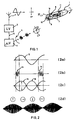
- Figure 1 is a view of the projectile and the equipment required for determining the roll angle position of the projectile
- Figure 2 shows the curve shape of the radiation components
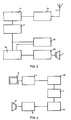
- Figure 3 shows the construction of the transmitter in a block diagram
- Figure 4 shows the construction of the receiver.
- FIG. 1 shows an outline diagram of how a roll angle reference can be unambiguously determined.
- a transmitter is positioned on the gun or in its immediate vicinity, which transmitter comprises two sets of transmission equipment, one for the long-wave band and one for the microwave band, these transmitting polarised electromagnetic radiation towards the shell 1.
- the long-wave transmitter 2 transmits via an antenna 3 a vertically polarised (VP), sinusoidal radiowave in the long-wave band (LF) and a microwave transmitter 4 transmits via the antenna 5 a directed circularly polarised wave (CP) towards the shell 1 on the microwave band ( V).
- the transmitter 2 sends synchronising codes to the transmitter 4 via connection 6.
- the long-wave band comprises the frequency range of 30-300 kHz and the mediumwave band (MF) comprises the frequency range of 300-3000 kHz.
- the frequency of the sinusoidal long-wave component thus lies in the LF range or lowest decile of the MF range, while the frequency of the microwave component exceeds 1 GHz.
- a receiver 7 which detects the magnetic field H LV of the long-wave signal, with the aid of a loop antenna 8, and a receiver 9 which detects the microwave signal from an antenna 10 situated in the rear of the shell.
- the two detected signals are applied to a microprocessor system 11 for evaluation.
- the transmitted long-wave signal 12 has a harmonic sinusoidal form, see Figure 2a.
- a synchronising pulse is sent from the long-wave transmitter 2 via the connection 6 to the microwave transmitter 4, which thus initiates transmission of the microwave radiation in the form of a pulse train 13, see Figure 2b.
- the antenna 8 in the shell for receiving the long-wave radiation is aligned with the aid of a reference point 14 in the shell.
- a signal 15 is obtained, and when the shell has turned 180°, a signal 16 is obtained, see Figure 2c.
- the received signal is shown relative to the orientation of the shell. Since the time between the nodes on the rotation envelope corresponds to half a turn of the shell, the microprocessor, knowing the speed of rotation, can calculate in a known manner the actual roll angle position of the shell.
- FIG. 3 a block diagram shows how the transmitter is constructed.
- the transmitter comprises a generator 17 which generates one of the two signals which are required for determining the position, namely the long-wave signal.
- the other position-determining signal is emitted by the microwave transmitter 18.
- the signals are amplified in amplifier 19 for the long-wave signal and amplifier 20 for the microwave signal, and the two signals are transmitted by antennae 3 and 4, respectively.
- FIG. 4 shows the construction of the receiver.
- the receiver comprises two antennae, a long-wave antenna 8 and a microwave antenna 10.
- the long-wave signal is incoming at a receiver 7 which amplifies the signal to levels which pass through an A/D converter 23.
- a microprocessor 11 reads the A/D converter and preserves these values in a register.
- the microwave signal is converted by the microwave receiver 9 to digital signals which are collected in a buffer 24.
- the main task of the microprocessor is to evaluate the long-wave signal and calculate the actual rotation position starting from earlier data. When information is incoming on the microwave channel, interrupt is requested. If the information contains a derivative indication, the information is updated upwards/downwards, and if it contains a command, the latter is decoded and executed.
- the time between each node in the long-wave signal corresponds to half a turn of the shell.
- the speed of rotation must be calculated. This can be calculated with knowledge of the time between the nodes of the rotation envelope.
- the momentary angle of rotation is calculated such that the time from the latest node gives a value which lies between 0° and 180°.
- the upward/downward information then gives an offset of 0° (up) or 180° (down). This combination then gives an unambiguous value for the instantaneous angular position.
Landscapes
- Engineering & Computer Science (AREA)
- Chemical & Material Sciences (AREA)
- Combustion & Propulsion (AREA)
- General Engineering & Computer Science (AREA)
- Radar Systems Or Details Thereof (AREA)
- Aiming, Guidance, Guns With A Light Source, Armor, Camouflage, And Targets (AREA)
- Management, Administration, Business Operations System, And Electronic Commerce (AREA)
- Position Fixing By Use Of Radio Waves (AREA)
- Length Measuring Devices With Unspecified Measuring Means (AREA)
Claims (4)
- Anordnung zum Bestimmen der Rollwinkellage eines rotierenden Projektils, Geschosses, Flugkörpers od. dgl. mit Hilfe polarisierter elektromagnetischer Strahlung, mit einem Sender zum Aussenden einer positionsbestimmenden polarisierten Strahlung in Richtung zum Projektil und einem im Projektil angeordneten Empfänger zum Empfangen der gesendeten Strahlung, wobei die ausgesandte polarisierte Strahlung aus zwei Komponenten besteht, einerseits einer ersten Strahlungskomponente (12) mit längerer Wellenlänge und andererseits einer zweiten Strahlungskomponente (13) mit kürzerer Wellenlänge, wobei die zweite Strahlungskomponente einen Impulszug (13) umfaßt, in welchem die Impulse anzeigen, daß die erste Strahlungskomponente sich in einer bestimmten Phasenlage befindet,
dadurch gekennzeichnet, daß die Impulse in der Mikrowellenkomponente (13) diejenigen Nullstellen der sinusförmigen Langwellenkomponente, die eine positive Ableitung, oder alternativ diejenigen, die eine negative Ableitung aufweisen, angeben. - Anordnung nach Anspruch 1,
dadurch gekennzeichnet, daß der Sender einen ersten Generator (17) und eine Antenne (3) zum Senden der ersten Strahlungskomponente, einen zweiten Generator (18) und eine Antenne (4) zum Senden der zweiten Strahlungskomponente, und eine Anordnung (21) aufweist, die detektiert, wenn die erste Strahlungskomponeten einen Nulldurchgang mit einem bestimmten Vorzeichen der Ableitung hat, und die an den zweiten Generator (18) ein Signal abgibt, wenn die erste Strahlungskomponente einen Nulldurchgang mit einem bestimmten Vorzeichen hat, wobei der zweite Generator (18) einen Impuls zur Anzeige des Nulldurchgangs aussendet. - Anordnung nach Anspruch 2,
dadurch gekennzeichnet, daß der Empfänger in dem Projektil einen Empfängerteil (7, 8) zum Empfang der ersten Strahlungskomponente, einen Empfängerteil (9, 10) zum Empfang der zweiten Strahlungskomponente und einen Mikroprozessor (11) zum Auswerten der ersten Strahlungskomponente aufweist. - Anordnung nach Anspruch 3,
dadurch gekennzeichnet, daß der Empfängerteil (7, 8) zum Empfang der ersten Strahlungskomponente eine Antenne (8) aufweist, die mit Hilfe eines Bezugspunktes (14) in dem Projektil ausgerichtet ist.
Applications Claiming Priority (2)
| Application Number | Priority Date | Filing Date | Title |
|---|---|---|---|
| SE9001370 | 1990-04-18 | ||
| SE9001370A SE465439B (sv) | 1990-04-18 | 1990-04-18 | Anordning foer bestaemma rullvinkellaeget hos en roterande projektil |
Publications (3)
| Publication Number | Publication Date |
|---|---|
| EP0453423A2 EP0453423A2 (de) | 1991-10-23 |
| EP0453423A3 EP0453423A3 (en) | 1993-01-13 |
| EP0453423B1 true EP0453423B1 (de) | 1996-09-18 |
Family
ID=20379194
Family Applications (1)
| Application Number | Title | Priority Date | Filing Date |
|---|---|---|---|
| EP91850055A Expired - Lifetime EP0453423B1 (de) | 1990-04-18 | 1991-03-05 | Rollwinkelermittlung |
Country Status (10)
| Country | Link |
|---|---|
| US (1) | US5163637A (de) |
| EP (1) | EP0453423B1 (de) |
| JP (1) | JP3251606B2 (de) |
| AU (1) | AU639774B2 (de) |
| CA (1) | CA2040685C (de) |
| DE (1) | DE69122155T2 (de) |
| ES (1) | ES2091315T3 (de) |
| FI (1) | FI108963B (de) |
| NO (1) | NO176982C (de) |
| SE (1) | SE465439B (de) |
Families Citing this family (23)
| Publication number | Priority date | Publication date | Assignee | Title |
|---|---|---|---|---|
| SE468726B (sv) * | 1991-07-02 | 1993-03-08 | Bofors Ab | Anordning foer rollvinkelbestaemning |
| DE4416211C2 (de) * | 1994-05-07 | 1996-09-26 | Rheinmetall Ind Gmbh | Verfahren und Vorrichtung zur Flugbahnkorrektur von Geschossen |
| DE19500993A1 (de) * | 1995-01-14 | 1996-07-18 | Contraves Gmbh | Verfahren zum Bestimmen der Rollage eines rollenden Flugobjektes |
| FR2748814B1 (fr) * | 1996-05-14 | 1998-08-14 | Tda Armements Sas | Dispositif de determination de l'orientation en roulis d'un engin volant, notamment d'une munition |
| US6450442B1 (en) * | 1997-09-30 | 2002-09-17 | Raytheon Company | Impulse radar guidance apparatus and method for use with guided projectiles |
| US6016990A (en) * | 1998-04-09 | 2000-01-25 | Raytheon Company | All-weather roll angle measurement for projectiles |
| SE513028C2 (sv) | 1998-10-29 | 2000-06-19 | Bofors Missiles Ab | Förfarande och anordning för att bestämma rollvinkel |
| SE515386C2 (sv) * | 1999-10-20 | 2001-07-23 | Bofors Weapon Sys Ab | Förfarande och anordning för att bestämma rollvinkeln hos en utskjutbar roterande kropp som roterar i sin bana |
| US7079070B2 (en) * | 2001-04-16 | 2006-07-18 | Alliant Techsystems Inc. | Radar-filtered projectile |
| FR2857088B1 (fr) * | 2003-07-04 | 2005-09-16 | Mbda France | Missile tournant emettant des impulsions lumineuses. |
| JP4593347B2 (ja) * | 2005-04-20 | 2010-12-08 | 横河電子機器株式会社 | 回転飛翔体 |
| US7589663B1 (en) * | 2006-01-20 | 2009-09-15 | The United States Of America As Represented By The Secretary Of The Army | System and method for the measurement of the unambiguous roll angle of a projectile |
| US7891298B2 (en) * | 2008-05-14 | 2011-02-22 | Pratt & Whitney Rocketdyne, Inc. | Guided projectile |
| US7823510B1 (en) | 2008-05-14 | 2010-11-02 | Pratt & Whitney Rocketdyne, Inc. | Extended range projectile |
| US8258999B2 (en) * | 2009-03-02 | 2012-09-04 | Omnitek Partners Llc | System and method for roll angle indication and measurement in flying objects |
| US7977613B2 (en) * | 2009-03-02 | 2011-07-12 | Omnitek Partners Llc | System and method for roll angle indication and measurement in flying objects |
| US8324542B2 (en) * | 2009-03-17 | 2012-12-04 | Bae Systems Information And Electronic Systems Integration Inc. | Command method for spinning projectiles |
| DE102009024508A1 (de) * | 2009-06-08 | 2011-07-28 | Rheinmetall Air Defence Ag | Verfahren zur Korrektur der Flugbahn einer endphasengelenkten Munition |
| US8598501B2 (en) * | 2011-06-30 | 2013-12-03 | Northrop Grumman Guidance an Electronics Co., Inc. | GPS independent guidance sensor system for gun-launched projectiles |
| FR2979995B1 (fr) * | 2011-09-09 | 2013-10-11 | Thales Sa | Systeme de localisation d'un engin volant |
| US9052171B2 (en) * | 2013-02-10 | 2015-06-09 | Omnitek Partners Llc | Methods and devices for providing guidance and control of low and high-spin rounds |
| US11578956B1 (en) | 2017-11-01 | 2023-02-14 | Northrop Grumman Systems Corporation | Detecting body spin on a projectile |
| US10962990B2 (en) * | 2019-08-07 | 2021-03-30 | Bae Systems Information And Electronic Systems Integration Inc. | Attitude determination by pulse beacon and low cost inertial measuring unit |
Family Cites Families (4)
| Publication number | Priority date | Publication date | Assignee | Title |
|---|---|---|---|---|
| US4030686A (en) * | 1975-09-04 | 1977-06-21 | Hughes Aircraft Company | Position determining systems |
| NL8600710A (nl) * | 1986-03-20 | 1987-10-16 | Hollandse Signaalapparaten Bv | Inrichting voor het bepalen van de rotatiestand van een om een as roterend voorwerp. |
| NL8900118A (nl) * | 1988-05-09 | 1989-12-01 | Hollandse Signaalapparaten Bv | Systeem voor het bepalen van de rotatiestand van een om een as roteerbaar voorwerp. |
| NL8900117A (nl) * | 1988-05-09 | 1989-12-01 | Hollandse Signaalapparaten Bv | Systeem voor het bepalen van de rotatiestand van een om een as roteerbaar voorwerp. |
-
1990
- 1990-04-18 SE SE9001370A patent/SE465439B/sv not_active IP Right Cessation
-
1991
- 1991-03-05 DE DE69122155T patent/DE69122155T2/de not_active Expired - Fee Related
- 1991-03-05 ES ES91850055T patent/ES2091315T3/es not_active Expired - Lifetime
- 1991-03-05 EP EP91850055A patent/EP0453423B1/de not_active Expired - Lifetime
- 1991-04-09 JP JP16694091A patent/JP3251606B2/ja not_active Expired - Fee Related
- 1991-04-17 FI FI911862A patent/FI108963B/fi active
- 1991-04-17 CA CA002040685A patent/CA2040685C/en not_active Expired - Fee Related
- 1991-04-17 NO NO911500A patent/NO176982C/no unknown
- 1991-04-17 AU AU75045/91A patent/AU639774B2/en not_active Ceased
- 1991-04-18 US US07/687,047 patent/US5163637A/en not_active Expired - Lifetime
Also Published As
| Publication number | Publication date |
|---|---|
| DE69122155T2 (de) | 1997-03-06 |
| AU7504591A (en) | 1991-10-24 |
| NO911500L (no) | 1991-10-21 |
| AU639774B2 (en) | 1993-08-05 |
| SE465439B (sv) | 1991-09-09 |
| EP0453423A2 (de) | 1991-10-23 |
| NO176982B (no) | 1995-03-20 |
| JPH063092A (ja) | 1994-01-11 |
| SE9001370L (de) | 1991-09-09 |
| US5163637A (en) | 1992-11-17 |
| ES2091315T3 (es) | 1996-11-01 |
| FI911862A7 (fi) | 1991-10-19 |
| FI911862A0 (fi) | 1991-04-17 |
| JP3251606B2 (ja) | 2002-01-28 |
| DE69122155D1 (de) | 1996-10-24 |
| FI108963B (fi) | 2002-04-30 |
| NO176982C (no) | 1995-06-28 |
| EP0453423A3 (en) | 1993-01-13 |
| CA2040685C (en) | 2002-04-16 |
| NO911500D0 (no) | 1991-04-17 |
| SE9001370D0 (sv) | 1990-04-18 |
| CA2040685A1 (en) | 1991-10-19 |
Similar Documents
| Publication | Publication Date | Title |
|---|---|---|
| EP0453423B1 (de) | Rollwinkelermittlung | |
| US5099246A (en) | Apparatus for determining roll position | |
| EP0521839B1 (de) | Rollwinkelermittlung | |
| US5102065A (en) | System to correct the trajectory of a projectile | |
| CA2271766C (en) | Impulse radar guidance apparatus and method for use with guided projectiles | |
| US4979696A (en) | System for determining the angular spin position of an object spinning about an axis | |
| US4750689A (en) | System for determining the angular spin position of an object spinning about an axis | |
| US20120292432A1 (en) | Method for correcting the trajectory of a projectile, in particular of a terminal phase-guided projectile, and projectile for carrying out the method | |
| WO2006019409A2 (en) | Rf attitude measurement system and method | |
| US6727843B1 (en) | Method and arrangement for determining the angle of roll of a launchable rotating body which rotates in its paths | |
| NO180130B (no) | Korreksjonssystem for trådlös korreksjon av kursen til utskutte prosjektiler | |
| US6806823B1 (en) | Passive radar detector for dualizing missile seeker capability | |
| US5233901A (en) | Roll angle determination | |
| US6572052B1 (en) | Process and device for determining roll angle | |
| JPS59137799A (ja) | 誘導飛しよう体 | |
| JPH03251696A (ja) | 管制装置 | |
| GB2231128A (en) | Activating a missile |
Legal Events
| Date | Code | Title | Description |
|---|---|---|---|
| PUAI | Public reference made under article 153(3) epc to a published international application that has entered the european phase |
Free format text: ORIGINAL CODE: 0009012 |
|
| AK | Designated contracting states |
Kind code of ref document: A2 Designated state(s): BE CH DE ES FR LI NL |
|
| PUAL | Search report despatched |
Free format text: ORIGINAL CODE: 0009013 |
|
| AK | Designated contracting states |
Kind code of ref document: A3 Designated state(s): BE CH DE ES FR LI NL |
|
| 17P | Request for examination filed |
Effective date: 19930525 |
|
| 17Q | First examination report despatched |
Effective date: 19950102 |
|
| RAP1 | Party data changed (applicant data changed or rights of an application transferred) |
Owner name: BOFORS AB |
|
| GRAH | Despatch of communication of intention to grant a patent |
Free format text: ORIGINAL CODE: EPIDOS IGRA |
|
| GRAH | Despatch of communication of intention to grant a patent |
Free format text: ORIGINAL CODE: EPIDOS IGRA |
|
| GRAA | (expected) grant |
Free format text: ORIGINAL CODE: 0009210 |
|
| AK | Designated contracting states |
Kind code of ref document: B1 Designated state(s): BE CH DE ES FR LI NL |
|
| ET | Fr: translation filed | ||
| REG | Reference to a national code |
Ref country code: CH Ref legal event code: NV Representative=s name: E. BLUM & CO. PATENTANWAELTE |
|
| REF | Corresponds to: |
Ref document number: 69122155 Country of ref document: DE Date of ref document: 19961024 |
|
| REG | Reference to a national code |
Ref country code: ES Ref legal event code: FG2A Ref document number: 2091315 Country of ref document: ES Kind code of ref document: T3 |
|
| PLBI | Opposition filed |
Free format text: ORIGINAL CODE: 0009260 |
|
| PLBF | Reply of patent proprietor to notice(s) of opposition |
Free format text: ORIGINAL CODE: EPIDOS OBSO |
|
| 26 | Opposition filed |
Opponent name: HOLLANDSE SIGNAALAPPARATEN B.V. Effective date: 19970609 |
|
| NLR1 | Nl: opposition has been filed with the epo |
Opponent name: HOLLANDSE SIGNAALAPPARATEN B.V. |
|
| K1C3 | Correction of patent application (complete document) published |
Effective date: 19911023 |
|
| PLBF | Reply of patent proprietor to notice(s) of opposition |
Free format text: ORIGINAL CODE: EPIDOS OBSO |
|
| PLBF | Reply of patent proprietor to notice(s) of opposition |
Free format text: ORIGINAL CODE: EPIDOS OBSO |
|
| PLBO | Opposition rejected |
Free format text: ORIGINAL CODE: EPIDOS REJO |
|
| PLBN | Opposition rejected |
Free format text: ORIGINAL CODE: 0009273 |
|
| STAA | Information on the status of an ep patent application or granted ep patent |
Free format text: STATUS: OPPOSITION REJECTED |
|
| 27O | Opposition rejected |
Effective date: 19991202 |
|
| NLR2 | Nl: decision of opposition | ||
| REG | Reference to a national code |
Ref country code: CH Ref legal event code: PFA Owner name: BOFORS AB Free format text: BOFORS AB# #691 80 KARLSKOGA (SE) -TRANSFER TO- BOFORS AB# #691 80 KARLSKOGA (SE) |
|
| PGFP | Annual fee paid to national office [announced via postgrant information from national office to epo] |
Ref country code: ES Payment date: 20080218 Year of fee payment: 18 Ref country code: CH Payment date: 20080229 Year of fee payment: 18 |
|
| PGFP | Annual fee paid to national office [announced via postgrant information from national office to epo] |
Ref country code: NL Payment date: 20080331 Year of fee payment: 18 |
|
| PGFP | Annual fee paid to national office [announced via postgrant information from national office to epo] |
Ref country code: DE Payment date: 20080523 Year of fee payment: 18 |
|
| PGFP | Annual fee paid to national office [announced via postgrant information from national office to epo] |
Ref country code: BE Payment date: 20080325 Year of fee payment: 18 |
|
| BERE | Be: lapsed |
Owner name: *BOFORS A.B. Effective date: 20090331 |
|
| PGFP | Annual fee paid to national office [announced via postgrant information from national office to epo] |
Ref country code: FR Payment date: 20090325 Year of fee payment: 19 |
|
| REG | Reference to a national code |
Ref country code: CH Ref legal event code: PL |
|
| NLV4 | Nl: lapsed or anulled due to non-payment of the annual fee |
Effective date: 20091001 |
|
| PG25 | Lapsed in a contracting state [announced via postgrant information from national office to epo] |
Ref country code: CH Free format text: LAPSE BECAUSE OF NON-PAYMENT OF DUE FEES Effective date: 20090331 Ref country code: DE Free format text: LAPSE BECAUSE OF NON-PAYMENT OF DUE FEES Effective date: 20091001 Ref country code: LI Free format text: LAPSE BECAUSE OF NON-PAYMENT OF DUE FEES Effective date: 20090331 |
|
| PG25 | Lapsed in a contracting state [announced via postgrant information from national office to epo] |
Ref country code: NL Free format text: LAPSE BECAUSE OF NON-PAYMENT OF DUE FEES Effective date: 20091001 Ref country code: BE Free format text: LAPSE BECAUSE OF NON-PAYMENT OF DUE FEES Effective date: 20090331 |
|
| REG | Reference to a national code |
Ref country code: ES Ref legal event code: FD2A Effective date: 20090306 |
|
| PG25 | Lapsed in a contracting state [announced via postgrant information from national office to epo] |
Ref country code: ES Free format text: LAPSE BECAUSE OF NON-PAYMENT OF DUE FEES Effective date: 20090306 |
|
| REG | Reference to a national code |
Ref country code: FR Ref legal event code: ST Effective date: 20101130 |
|
| PG25 | Lapsed in a contracting state [announced via postgrant information from national office to epo] |
Ref country code: FR Free format text: LAPSE BECAUSE OF NON-PAYMENT OF DUE FEES Effective date: 20100331 |