EP0453142A2 - Bandvorschubvorrichtung für einen geräuschlosen und billigen Anschlagdrucker - Google Patents
Bandvorschubvorrichtung für einen geräuschlosen und billigen Anschlagdrucker Download PDFInfo
- Publication number
- EP0453142A2 EP0453142A2 EP91303044A EP91303044A EP0453142A2 EP 0453142 A2 EP0453142 A2 EP 0453142A2 EP 91303044 A EP91303044 A EP 91303044A EP 91303044 A EP91303044 A EP 91303044A EP 0453142 A2 EP0453142 A2 EP 0453142A2
- Authority
- EP
- European Patent Office
- Prior art keywords
- ribbon
- hammer
- platen
- ribbons
- motor
- Prior art date
- Legal status (The legal status is an assumption and is not a legal conclusion. Google has not performed a legal analysis and makes no representation as to the accuracy of the status listed.)
- Granted
Links
Images


Classifications
-
- B—PERFORMING OPERATIONS; TRANSPORTING
- B41—PRINTING; LINING MACHINES; TYPEWRITERS; STAMPS
- B41J—TYPEWRITERS; SELECTIVE PRINTING MECHANISMS, i.e. MECHANISMS PRINTING OTHERWISE THAN FROM A FORME; CORRECTION OF TYPOGRAPHICAL ERRORS
- B41J23/00—Power drives for actions or mechanisms
- B41J23/02—Mechanical power drives
- B41J23/025—Mechanical power drives using a single or common power source for two or more functions
-
- B—PERFORMING OPERATIONS; TRANSPORTING
- B41—PRINTING; LINING MACHINES; TYPEWRITERS; STAMPS
- B41J—TYPEWRITERS; SELECTIVE PRINTING MECHANISMS, i.e. MECHANISMS PRINTING OTHERWISE THAN FROM A FORME; CORRECTION OF TYPOGRAPHICAL ERRORS
- B41J33/00—Apparatus or arrangements for feeding ink ribbons or like character-size impression-transfer material
- B41J33/14—Ribbon-feed devices or mechanisms
- B41J33/16—Ribbon-feed devices or mechanisms with drive applied to spool or spool spindle
- B41J33/22—Ribbon-feed devices or mechanisms with drive applied to spool or spool spindle by gears or pulleys
-
- B—PERFORMING OPERATIONS; TRANSPORTING
- B41—PRINTING; LINING MACHINES; TYPEWRITERS; STAMPS
- B41J—TYPEWRITERS; SELECTIVE PRINTING MECHANISMS, i.e. MECHANISMS PRINTING OTHERWISE THAN FROM A FORME; CORRECTION OF TYPOGRAPHICAL ERRORS
- B41J9/00—Hammer-impression mechanisms
- B41J9/26—Means for operating hammers to effect impression
- B41J9/28—Cams
Definitions
- This invention relates to an impact printer engine for use in low cost typewriters in which impact noise generation, during the printing operation, is substantially reduced.
- the office has, for many years, been a stressful environment due, in part, to the large number of objectionable noise generators, such as typewriters, high speed impact printers, paper shredders, and other office machinery. Where several such devices are placed together in a single room, the cumulative noise pollution may even be hazardous to the health and well being of its occupants. The situation is well recognized and has been addressed by governmental bodies who have set standards for maximum acceptable noise levels in office environments. Attempts have been made by office machinery designers, in the field of impact printers, to reduce the noise pollution. Some of these methods include enclosing impact printers in sound attenuating covers, designing impact printers in which the impact noise is reduced, and designing quieter printers based on non-impact technologies such as ink jet and thermal transfer.
- objectionable noise generators such as typewriters, high speed impact printers, paper shredders, and other office machinery.
- the low cost personal typewriter is purchased primarily for home usage (including both personal and in-home office) and for school usage. It is particularly desirable in these environments to reduce the acoustic noise level of the printing mechanism at the source to levels which are unobtrusive. For example, in the home, other members of the family should not be distracted by the clatter of typing if conducted in common rooms. In a secondary school or college setting, colleagues and others should not be disturbed if the user types in a library, a study hall or a dormitory room. Heretofore such usage has not been possible because typewriters are notoriously noisy devices. The silent operation of our low cost quiet typewriter will enable such usage because silence transports such useful appliances into new physical settings and enhances portability. A derived benefit will be freer communication among work group members as the user is able to work directly in the group in a non-irritating manner.
- the industrial typewriter market segment is at the high end of the product cost continuum, i.e. in the $1000 to $2000 range.
- the incremental increase in manufacturing costs necessitated by numerous design changes represents a relatively small percentage of the product cost which is passed on to the ultimate purchaser.
- any modification necessitated by the implementation of a sound reduction design will of necessity be extremely low in cost because the incremental increase in product cost to the consumer will not warrant a large percentage rise in this market.
- Noise measurements are often referenced as dBA values.
- the "A" scale by which the sound values have been identified, represents humanly perceived levels of loudness as opposed to absolute values of sound intensity.
- dB or dBA
- the scale is logarithmic and that a 10 dB difference equals a factor 10, a 20 dB difference equals a factor of 100, a 30 dB equals a factor of 1000, and so on.
- Typical typewriters generate impact noise in the range of 65 to just over 80 dBA. These sound levels are deemed to be intrusive. For example, the IBM Selectric ball unit generates about 78 dBA, while the Xerox Memorywriter generates about 68 dBA, and the low cost Smith Corona Correcting Portable generates about 70 dBA. When reduced to the high 50s dBA, the noise is construed to be objectionable or annoying. It would be highly desirable to reduce the impact noise to a value in the vicinity of 50 dBA.
- the low cost typewriter of the present invention has been typically measured at about 50 dBA. This represents a dramatic improvement on the order of about 100 times less sound pressure than present day low cost typewriters, a notable achievement toward a less stressful environment.
- the major source of noise in the modern typewriter is produced as the hammer impacts and drives a character pad to form an impression on a receptor sheet.
- Character pads are carried upon and transported past a print station at the ends of the rotating spokes of a printwheel. When a selected character is to be printed, it is stopped at the print station and the hammer drives it against a ribbon, the receptor sheet and a supporting platen, with sufficient force to release ink from the ribbon onto the receptor sheet.
- the platen deformation impact is very short, on the order of 100 microseconds duration. Intuitively it is known that a sharp, rapid impact will be noisy and that a slow impact will be less noisy. Thus, if the impact duration were slowed it would be possible to make the device quieter.
- the mean time available between character impacts is about 85 to 90 milliseconds. More of that available time can be used for the hammer impact than the usual 100 microseconds. If, for example, the platen deformation time were stretched to even 5 to 10 milliseconds this would represent a fifty to one hundred-fold increase, or stretch, in the impact pulse width.
- a mass transformer comprising a heavy rockable bail bar driven by a voice coil motor, urges a push rod toward and away from the platen in a controlled manner.
- the push rod in turn moves a print tip (hammer) into deforming contact with the platen.
- a sensor mounted upon the print tip indicates the moment of contact with the platen so that an additional application of kinetic energy may be provided by the voice coil motor at that juncture.
- a suitable controller connected to the voice coil motor, moves the print tip across a throat distance between its home position and the surface of the platen in a controlled ballistic manner, i.e. the print tip is set in motion and will arrive at the platen surface regardless of its location (“self levelling"), and then controls the duration of the platen deformation with this high effective mass.
- a serial impact printer comprising a support frame, a platen mounted for rotation upon said support frame, a print element having character imprinting portions disposed thereon, a print element selector for moving said print element to position a selected character imprinting portion at a printing position, a marking ribbon and a lift-off ribbon, each ribbon being selectively positionable between said print element and said platen, a hammer for moving a selected character imprinting portion for deforming said platen with a printing force, means for moving said hammer toward and away from said platen, and a carriage mounted for reciprocating movement generally parallel to said platen, said carriage supporting thereon said print element, said print element selector, said marking and lift-off ribbons, means for positioning said ribbons, means for advancing said marking ribbon, means for advancing said lift-off ribbon, said hammer, and said means for moving said hammer, characterised in that
- said means for moving said hammer, said means for positioning said ribbons, said means for advancing said marking ribbon, and said means for advancing said lift-off ribbon includes a single D.C. motor which drives said hammer when said motor is driven either in clockwise or in counterclockwise directions of rotation from a home position, which positions and drives said means for advancing said marking ribbon in only one direction of rotation of said motor from said home position, and which positions and drives said lift-off ribbon in only the opposite direction of rotation of said motor from said home position, whereby at each hammer impact one of said ribbons is being impacted.
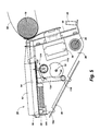
- An enclosure (only the base 12 is shown) houses its relatively few moving parts.
- Vertically upstanding left and right side plates 14 and 16 are each secured to the base and support platen 18 therebetween, for rotation in seats therein.
- the platen is driven by a suitable motor (not shown) through a gear train including driving gear 20 and driven gear 22 on the platen shaft 24.
- the side plates also support the ends of a highly polished guide rod 26 and the ends of reaction bar 28 having an accurately machined guiding edge 30.
- the reaction bar is mounted so as to be adjusted to insure that its guiding edge is parallel to the platen surface.
- a printer carriage 32 comprised of carriage frame plates 34 and 36 each having a bearing 38 mounted thereon is supported upon the guide rod 26 for reciprocating movement therealong, across the length of the platen.
- Carriage reciprocation is controlled by a motor (not shown) which drives a toothed spacing belt 40, secured to the carriage, over pulleys 42 and 44.
- a motor not shown
- the shoe is made of a hard, low friction material, such as Delrin®.
- This carriage mounting arrangement facilitates inexpensive assembly of the printing device because it eliminates criticality in the placement of the guide rod, requiring only one element, the reaction bar 28, to be accurately positioned.
- the guiding edge 30 may be accurately positioned parallel to the platen, so that as the carriage 32 traverses the printer all the printing elements carried thereon will be in their proper position relative to the platen.
- the printing elements comprise a printwheel 50, a hammer assembly 52 and a ribbon pack assembly 54 (seen in Figures 4 and 5).
- a printwheel drive motor 56 mounted on the carriage frame plates 34 and 36 has a drive coupling 58 to which a printwheel hub 60 may be connected for rotation of the character pads 62 (located at the ends of printwheel spokes 64) past a print station adjacent to the platen. Selective rotation of the drive motor 56 under processor control, initiated by keystrokes, locates and arrests the desired character pad 62 at the print station.
- a resilient card guide 66 also mounted on the carriage frame plates holds an image receptor sheet 68 in intimate contact with the platen surface.
- the hammer assembly 52 is best seen in Figure 4 wherein carriage frame plate 34 has been cut away to better reveal it.
- a hammer actuating D.C. motor 70 is mounted upon carriage frame plate 34 with its drive shaft 72 extending through and beyond both frame plates.
- Drive cam 74 secured to the shaft moves cam follower 76 to rotate bell crank 78, upon which it is carried, about pivot pin 80.
- the hammer 82 is pinned at the opposite end of the bell crank and slides through a stationary guide bearing.
- the cam rotation is effected in a predetermined controlled manner by the D.C. motor, in response to signals received from the controller 86, mounted upon circuit board 88 secured to the carriage, the hammer is moved toward and away from the platen.
- the motor 70 rotates a timing disc 90 which may be in the form of a simple optical encoder capable of generating displacement and direction outputs for sending positioning information back to the controller.
- the controller uses this information to keep track of the instantaneous hammer position, as well as to derive system velocity.
- D.C. motors of the type employed in this invention are in widespread use in small appliances. Consequently they are inexpensive and readily available from many sources. Most importantly, however, D.C. motors have characteristics particularly desirable for the application of the hammer force required in the present invention. Namely, they achieve high speeds under light load and produce large torques at low speeds. In the present application, the motor can initially rapidly move the hammer to close the throat between the hammer "home" position and the initiation of platen deformation and subsequently apply the necessary torque to control the deformation force after contact has been made. Furthermore, contact may be determined easily by sensing a sudden decrease in velocity of the motor. Motor motion can be controlled with a simple feedback system under processor control based upon the position, speed and direction of timing disc 90.
- a representation of the cam displacement characteristics can be seen in Figure 7.
- a first cam region will result in the illustrated sinusoidal hammer displacement. Harmonic motion has been selected in order to move the hammer smoothly so as to minimize acoustic noise and component wear.
- a second cam region will result in the shallow straight line displacement (e.g. 25 ⁇ m/degree of motor rotation). The straight line cam region should overlap the range in which impact is expected, i.e.
- reaction bar 28 must be adjusted toward or away from the platen surface so that the x1 - x2 displacement range of the drive cam 74 corresponds with those receptor sheet conditions.
- the linearity of this second region results in a linear relationship between the motor current and the hammer force so that its slope is selected to yield the maximum force needed for a particular system in view of the torque available from the motor.
- the print force is resolved as the hammer 82 is driven against the platen and the shoe 46 is driven against the reaction bar 28.
- reaction bar transforms the hammer into a high effective mass at the moment of impact, enabling the high print force to be obtained at the slow hammer speed.
- the print force and the reaction force would be equal and opposite and no other system elements would experience and force at impact.
- the ribbon pack assembly 54 comprising a marking ribbon cartridge 92 and a lift-off ribbon cartridge 94, may be removably mounted upon a ribbon deck 96 secured atop the carriage frame plates so as to pivot about pivot pin 98.
- An arm 100 depending from the deck is connected to the frame plates via spring 102 which urges the deck in a counterclockwise direction (as viewed in Figure 5) about pivot pin 98 for raising the lift-off ribbon to the print position.
- the marking ribbon and lift-off ribbon each housed within its respective cartidge, each may be selectively positioned in front of the hammer, at the print position, and advanced by the single D.C. motor 70.
- One such arrangement is schematically illustrated.
- a driving worm gear 104 is mounted upon motor drive shaft 72 through a one-way clutch 106 for turning driven worm gear 108, also mounted for rotation through a carriage mounted one-way clutch 110.
- the worm gears can only move in one direction of motor shaft rotation.
- the worm gears When the worm gears are rotated they drive a marking ribbon drive capstan 112 terminating in a cruciform key 114. The key is received in a mating slot in the marking ribbon cartridge for advancing the marking ribbon in a known manner.
- the lift-off ribbon is carried below the marking ribbon and is positioned at the printing station when the ribbon deck 96 is pivoted upwardly. Since the ribbon deck 96 is normally urged in its upward position by spring 102 it is necessary to provide means for normally holding it in its lower, printing position. This is accomplished by the ribbon deck positioning cam 116, also secured to the motor drive shaft 72, in combination with cam follower 118 secured at the end of arm 120 depending from the ribbon deck. In its "home" position, the deck positioning cam draws the deck downwardly. When it is desired to lift the deck in order to effect correction, the deck positioning cam 116 is rotated from its home position to allow spring 102 to pivot the deck upwardly.
- the lift-off ribbon is incrementally advanced by a capstan 122 driven off the depending arm 120 by a conventional advancing mechanism, such as a ratchet and pawl arrangement 124.
- the hammer drive cam 74 may be in the form of a mirror image, as shown. Rotation from a home position, in both the clockwise and counterclockwise directions, will drive the hammer similarly. As illustrated in Figure 8A, the hammer drive cam 74 would be rotated to about 170° and back (from its "home” position) for the normal printing cycle, during which the hammer is driven and the one way clutches 106 and 110 allow the marking ribbon to be advanced. When correction is desired, motor rotates the drive cam 74 to about -170° and back (from its "home” position).
- Rotation in this sense does not drive the marking ribbon advancing capstan but it does rotate the deck positioning cam 116 (as shown in Figure 8B) to allow the spring 102 to raise the ribbon deck 96 for positioning the lift-off ribbon at the printing zone. Additionally, it advances the lift-off ribbon as set forth above.
- FIG. 9 there is illustrated a state diagram showing a typical print cycle for this device wherein hammer velocity is plotted against its displacement from its "home" position.
- Acceleration State A the hammer is accelerated forward for approximately half the distance to the expected impact point by applying a controlled current to the D.C. motor.
- Deceleration State B the hammer is decelerated toward point x1 (the beginning of the straight portion of the transfer characteristic) by applying a reverse voltage to the D.C. motor until the velocity reaches a predetermined slow approach velocity of about one to two inches per second.
- a constant current is applied to the motor to generate a fixed deformation force, wherein the magnitude of the impression current depends upon the force required to print the selected character.
- Return State E is effected during which the D.C. motor is accelerated in reverse for approximately one-half the distance to the "home" position.
- Deceleration State F the hammer is decelerated by applying a reverse potential until it is near its "home” position, followed by a dynamic braking to settle the hammer at its "home” position.
- the cam location of the hammer impact position at the end of Approach State C is updated in memory.
- this updated information is used to calculate a new deceleration initiation point.
- the system provides an automatic "rolling" compensation along the axial length of the platen for overcoming mechanical variations in the distance from the hammer "home” position to the platen surface, such as platen skew, platen eccentricity, paper stock thickness, etc..
- An initialization cycle may be implemented prior to the initial print cycle in order to establish memory values. Alternatively, initialization default values may be used based upon the assumption that impact will occur at a minimum position. Then in each subsequent cycle the control algorithm adjusts the braking point so as to minimize the duration of the slow Approach State C.
Landscapes
- Impression-Transfer Materials And Handling Thereof (AREA)
- Accessory Devices And Overall Control Thereof (AREA)
Applications Claiming Priority (2)
| Application Number | Priority Date | Filing Date | Title |
|---|---|---|---|
| US07/510,640 US5011309A (en) | 1990-04-18 | 1990-04-18 | Ribbon drive for low cost quiet impact printer |
| US510640 | 1990-04-18 |
Publications (3)
| Publication Number | Publication Date |
|---|---|
| EP0453142A2 true EP0453142A2 (de) | 1991-10-23 |
| EP0453142A3 EP0453142A3 (en) | 1992-03-11 |
| EP0453142B1 EP0453142B1 (de) | 1995-01-11 |
Family
ID=24031565
Family Applications (1)
| Application Number | Title | Priority Date | Filing Date |
|---|---|---|---|
| EP91303044A Expired - Lifetime EP0453142B1 (de) | 1990-04-18 | 1991-04-05 | Bandvorschubvorrichtung für einen geräuschlosen und billigen Anschlagdrucker |
Country Status (4)
| Country | Link |
|---|---|
| US (1) | US5011309A (de) |
| EP (1) | EP0453142B1 (de) |
| JP (1) | JPH04223187A (de) |
| DE (1) | DE69106566T2 (de) |
Cited By (1)
| Publication number | Priority date | Publication date | Assignee | Title |
|---|---|---|---|---|
| EP0538998A3 (en) * | 1991-10-24 | 1993-06-23 | Smith Corona Corporation | Quiet impact printer mechanism |
Families Citing this family (1)
| Publication number | Priority date | Publication date | Assignee | Title |
|---|---|---|---|---|
| US5183344A (en) * | 1991-05-31 | 1993-02-02 | Smith Corona Corporation | Quiet impact printer mechanism |
Family Cites Families (21)
| Publication number | Priority date | Publication date | Assignee | Title |
|---|---|---|---|---|
| US1261751A (en) * | 1912-05-27 | 1918-04-09 | Noiseless Typewriter Co | Type-writing machine. |
| US3995547A (en) * | 1970-02-27 | 1976-12-07 | Kabushiki Kaisha Suwa Seikosha | Compact flying printer |
| US3986594A (en) * | 1974-11-27 | 1976-10-19 | Lrc, Inc. | Serial impact calculator printer |
| IT1083039B (it) * | 1977-07-29 | 1985-05-21 | Giolitti Alberto | Unita stampante a controllo elettronico particolarmente per macchine per scrivere |
| US4266479A (en) * | 1977-12-12 | 1981-05-12 | Sperry Corporation | Multi-function mechanical printer drive means |
| JPS602994B2 (ja) * | 1978-12-23 | 1985-01-25 | キヤノン株式会社 | プリンタ |
| DE2919209C2 (de) * | 1979-05-12 | 1982-09-02 | Triumph-Adler Aktiengesellschaft für Büro- und Informationstechnik, 8500 Nürnberg | Steuervorrichtung für Schreibmaschinen |
| JPS5910916B2 (ja) * | 1979-07-09 | 1984-03-12 | アルプス電気株式会社 | 印字装置 |
| IT1119622B (it) * | 1979-12-21 | 1986-03-10 | Olivetti & Co Spa | Macchina per scrivere elettronica |
| JPS5747664A (en) * | 1980-09-05 | 1982-03-18 | Alps Electric Co Ltd | Serial printer |
| US4449835A (en) * | 1981-05-07 | 1984-05-22 | Epson Corporation | Printing device |
| US4461588A (en) * | 1981-06-19 | 1984-07-24 | Matsushita Electric Industrial Co., Ltd. | Serial printing mechanism |
| JPS60139950A (ja) * | 1983-12-27 | 1985-07-24 | Seiko Epson Corp | 動力伝達装置 |
| JPH07407B2 (ja) * | 1985-01-07 | 1995-01-11 | キヤノン株式会社 | 印字制御方法 |
| US4668112A (en) * | 1985-07-02 | 1987-05-26 | Xerox Corporation | Quiet impact printer |
| US4681469A (en) * | 1985-07-02 | 1987-07-21 | Xerox Corporation | Quiet impact printer |
| US4758108A (en) * | 1985-09-26 | 1988-07-19 | Brother Kogyo Kabushiki Kaisha | Printing apparatus with carriage drive utilized to feed print and erase ribbons and/or to feed the print ribbon and shift the erase ribbon |
| US4698567A (en) * | 1985-12-27 | 1987-10-06 | Xerox Corporation | Ribbon deck motor control |
| DE3729309C1 (de) * | 1987-09-02 | 1989-01-26 | Triumph Adler Ag | Schreib- oder aehnliche Maschine mit einem Typenrad |
| CH680425A5 (de) * | 1987-10-31 | 1992-08-31 | Triumph Adler Ag | |
| US4893950A (en) * | 1988-09-28 | 1990-01-16 | Xerox Corporation | Apparatus and method for controlling the positioning of marking elements in a serial impact printer |
-
1990
- 1990-04-18 US US07/510,640 patent/US5011309A/en not_active Expired - Fee Related
-
1991
- 1991-04-05 EP EP91303044A patent/EP0453142B1/de not_active Expired - Lifetime
- 1991-04-05 DE DE69106566T patent/DE69106566T2/de not_active Expired - Fee Related
- 1991-04-11 JP JP3079294A patent/JPH04223187A/ja active Pending
Cited By (1)
| Publication number | Priority date | Publication date | Assignee | Title |
|---|---|---|---|---|
| EP0538998A3 (en) * | 1991-10-24 | 1993-06-23 | Smith Corona Corporation | Quiet impact printer mechanism |
Also Published As
| Publication number | Publication date |
|---|---|
| JPH04223187A (ja) | 1992-08-13 |
| DE69106566T2 (de) | 1995-08-03 |
| EP0453142B1 (de) | 1995-01-11 |
| DE69106566D1 (de) | 1995-02-23 |
| US5011309A (en) | 1991-04-30 |
| EP0453142A3 (en) | 1992-03-11 |
Similar Documents
| Publication | Publication Date | Title |
|---|---|---|
| US3854563A (en) | Arcuate printer | |
| JPH04296582A (ja) | プリンタ | |
| CA1260862A (en) | Quiet impact printer | |
| US5066150A (en) | Low cost quiet impact printer | |
| US4147438A (en) | Serial printer for typewriters, teleprinters and data processors | |
| EP0453142B1 (de) | Bandvorschubvorrichtung für einen geräuschlosen und billigen Anschlagdrucker | |
| JPS627572A (ja) | 低騒音シリアルプリンタ | |
| US5199804A (en) | Quiet impact printer mechanism | |
| US4893950A (en) | Apparatus and method for controlling the positioning of marking elements in a serial impact printer | |
| EP0490643B1 (de) | Anschlagdrucker | |
| US4737043A (en) | Impact mechanism for quiet impact printer | |
| US4575269A (en) | Portable electronic typewriter | |
| GB2148006A (en) | Vibration preventing device | |
| US4859096A (en) | Impact mechanism for impact printer | |
| JPH0414634B2 (de) | ||
| US3353645A (en) | Ambulatory typewriter apparatus having only one driving means | |
| JP2516662Y2 (ja) | 印字ヘッドギャップ自動調整機構 | |
| US4491069A (en) | Printing hammer driver mechanism | |
| US5183344A (en) | Quiet impact printer mechanism | |
| JP2844009B2 (ja) | プリンタのヘッド間隙自動調整装置 | |
| JPH0416349B2 (de) | ||
| CA1260861A (en) | Impact mechanism for quiet impact printer | |
| US2045997A (en) | Typewriting machine | |
| JPH04161369A (ja) | ドットプリンタのヘッドギャップ調整装置 | |
| JPH04334467A (ja) | 印字装置 |
Legal Events
| Date | Code | Title | Description |
|---|---|---|---|
| PUAI | Public reference made under article 153(3) epc to a published international application that has entered the european phase |
Free format text: ORIGINAL CODE: 0009012 |
|
| AK | Designated contracting states |
Kind code of ref document: A2 Designated state(s): DE FR GB |
|
| PUAL | Search report despatched |
Free format text: ORIGINAL CODE: 0009013 |
|
| AK | Designated contracting states |
Kind code of ref document: A3 Designated state(s): DE FR GB |
|
| 17P | Request for examination filed |
Effective date: 19920904 |
|
| 17Q | First examination report despatched |
Effective date: 19940126 |
|
| GRAA | (expected) grant |
Free format text: ORIGINAL CODE: 0009210 |
|
| AK | Designated contracting states |
Kind code of ref document: B1 Designated state(s): DE FR GB |
|
| REF | Corresponds to: |
Ref document number: 69106566 Country of ref document: DE Date of ref document: 19950223 |
|
| ET | Fr: translation filed | ||
| PLBE | No opposition filed within time limit |
Free format text: ORIGINAL CODE: 0009261 |
|
| STAA | Information on the status of an ep patent application or granted ep patent |
Free format text: STATUS: NO OPPOSITION FILED WITHIN TIME LIMIT |
|
| 26N | No opposition filed | ||
| PGFP | Annual fee paid to national office [announced via postgrant information from national office to epo] |
Ref country code: GB Payment date: 19980327 Year of fee payment: 8 |
|
| PGFP | Annual fee paid to national office [announced via postgrant information from national office to epo] |
Ref country code: FR Payment date: 19980409 Year of fee payment: 8 |
|
| PGFP | Annual fee paid to national office [announced via postgrant information from national office to epo] |
Ref country code: DE Payment date: 19980414 Year of fee payment: 8 |
|
| PG25 | Lapsed in a contracting state [announced via postgrant information from national office to epo] |
Ref country code: GB Free format text: LAPSE BECAUSE OF NON-PAYMENT OF DUE FEES Effective date: 19990405 |
|
| GBPC | Gb: european patent ceased through non-payment of renewal fee |
Effective date: 19990405 |
|
| PG25 | Lapsed in a contracting state [announced via postgrant information from national office to epo] |
Ref country code: FR Free format text: LAPSE BECAUSE OF NON-PAYMENT OF DUE FEES Effective date: 19991231 |
|
| REG | Reference to a national code |
Ref country code: FR Ref legal event code: ST |
|
| PG25 | Lapsed in a contracting state [announced via postgrant information from national office to epo] |
Ref country code: DE Free format text: LAPSE BECAUSE OF NON-PAYMENT OF DUE FEES Effective date: 20000201 |