EP0452169A1 - Improvements to hydraulic anti-vibration bushes - Google Patents
Improvements to hydraulic anti-vibration bushes Download PDFInfo
- Publication number
- EP0452169A1 EP0452169A1 EP91400686A EP91400686A EP0452169A1 EP 0452169 A1 EP0452169 A1 EP 0452169A1 EP 91400686 A EP91400686 A EP 91400686A EP 91400686 A EP91400686 A EP 91400686A EP 0452169 A1 EP0452169 A1 EP 0452169A1
- Authority
- EP
- European Patent Office
- Prior art keywords
- chamber
- pockets
- channel
- sleeve
- annular
- Prior art date
- Legal status (The legal status is an assumption and is not a legal conclusion. Google has not performed a legal analysis and makes no representation as to the accuracy of the status listed.)
- Granted
Links
Images

Classifications
-
- F—MECHANICAL ENGINEERING; LIGHTING; HEATING; WEAPONS; BLASTING
- F16—ENGINEERING ELEMENTS AND UNITS; GENERAL MEASURES FOR PRODUCING AND MAINTAINING EFFECTIVE FUNCTIONING OF MACHINES OR INSTALLATIONS; THERMAL INSULATION IN GENERAL
- F16F—SPRINGS; SHOCK-ABSORBERS; MEANS FOR DAMPING VIBRATION
- F16F13/00—Units comprising springs of the non-fluid type as well as vibration-dampers, shock-absorbers, or fluid springs
- F16F13/04—Units comprising springs of the non-fluid type as well as vibration-dampers, shock-absorbers, or fluid springs comprising both a plastics spring and a damper, e.g. a friction damper
- F16F13/06—Units comprising springs of the non-fluid type as well as vibration-dampers, shock-absorbers, or fluid springs comprising both a plastics spring and a damper, e.g. a friction damper the damper being a fluid damper, e.g. the plastics spring not forming a part of the wall of the fluid chamber of the damper
- F16F13/08—Units comprising springs of the non-fluid type as well as vibration-dampers, shock-absorbers, or fluid springs comprising both a plastics spring and a damper, e.g. a friction damper the damper being a fluid damper, e.g. the plastics spring not forming a part of the wall of the fluid chamber of the damper the plastics spring forming at least a part of the wall of the fluid chamber of the damper
- F16F13/14—Units of the bushing type, i.e. loaded predominantly radially
- F16F13/16—Units of the bushing type, i.e. loaded predominantly radially specially adapted for receiving axial loads
Abstract
Description
L'invention est relative aux manchons antivibratoires hydrauliques comprenant deux armatures rigides tubulaires s'entourant l'une l'autre et de préférence de révolution au moins en partie autour d'un axe X, coaxiales et concentriques au moins sous charge, armatures réunies entre elles par un corps en élastomère conformé de façon à former avec celles-ci au moins deux poches étanches opposées diamétralement selon une direction Y et communiquant entre elles par un canal étroit, l'ensemble desdites poches et dudit canal étant rempli d'un liquide amortisseur.The invention relates to hydraulic antivibration sleeves comprising two rigid tubular frames surrounding each other and preferably of revolution at least in part around an axis X, coaxial and concentric at least under load, frames joined between they by an elastomer body shaped so as to form with them at least two sealed pockets diametrically opposite in a direction Y and communicating with each other by a narrow channel, all of said pockets and said channel being filled with a damping liquid .
De tels manchons sont destinés à être montés aux fins de liaison -voire de support proprement dit- et d'amortissement entre deux pièces rigides solidarisables respectivement avec les deux armatures et susceptibles de subir l'une par rapport à l'autre des oscillations orientées selon la direction diamétrale Y, l'ensemble étant agencé de façon telle que, pour certaines au moins de ces oscillations, le liquide soit refoulé alternativement de l'une des poches vers l'autre et inversement à travers le canal étroit, ce qui crée dans ce liquide, pour une fréquence donnée des oscillations dépendant des cotes dudit canal, un phénomène de résonance propre à amortir la transmission de ces oscillations de l'une des armatures à l'autre.Such sleeves are intended to be mounted for the purpose of connection - or even of the support itself - and of damping between two rigid parts which can be secured respectively to the two frames and which are liable to undergo relative to one another oscillations oriented according to the diametral direction Y, the assembly being arranged in such a way that, for at least some of these oscillations, the liquid is discharged alternately from one of the pockets towards the other and vice versa through the narrow channel, which creates in this liquid, for a given frequency of oscillations depending on the dimensions of said channel, a resonance phenomenon capable of damping the transmission of these oscillations from one of the reinforcements to the other.
Les manchons du genre en question sont par exemple destinés à être interposés entre, d'une part, un châssis ou caisse de véhicule et, d'autre part, le moteur à combustion interne ou le train avant ou arrière de ce véhicule.The sleeves of the type in question are for example intended to be interposed between, on the one hand, a chassis or body of the vehicle and, on the other hand, the internal combustion engine or the front or rear axle of this vehicle.
L'invention concerne plus particulièrement, parmi les manchons ci-dessus, ceux qui sont destinés à exercer l'effet d'amortissement signalé entre les deux armatures tubulaires, non seulement selon la direction diamètrale Y, mais aussi selon la direction axiale X.The invention relates more particularly, among the above sleeves, those which are intended to exert the damping effect indicated between the two tubular reinforcements, not only in the diametrical direction Y, but also in the axial direction X.
Il a été proposé à cet effet de former à une extrémité axiale du manchon une chambre annulaire délimitée respectivement par des prolongements des deux armatures tubulaires, par le corps intermédiaire en élastomère et par une paroi élastique résistante à la compression axiale et interposée axialement entre les prolongements ci-dessus et de relier cette chambre à l'une au moins des poches par un canal étroit, l'ensemble de ce canal et de cette poche étant rempli par le liquide amortisseur (brevet JP n° 59-37 349).It has been proposed for this purpose to form at an axial end of the sleeve an annular chamber defined respectively by extensions of the two tubular reinforcements, by the intermediate elastomer body and by an elastic wall resistant to axial compression and interposed axially between the extensions above and to connect this chamber to at least one of the pockets by a narrow channel, the whole of this channel and of this pocket being filled with the damping liquid (JP patent n ° 59-37 349).
Dans cette construction, la chambre annulaire est du type des "chambres de travail", c'est-à-dire est délimitée en partie par une paroi travaillant élastiquement et il en est de même des poches du manchon, ce qui présente l'inconvénient de créer une interférence entre les deux types d'amortissement assurés par le manchon selon respectivement les deux directions X et Y.In this construction, the annular chamber is of the type of "working chambers", that is to say is delimited in part by an elastically working wall and the same is true of the pockets of the sleeve, which has the drawback create an interference between the two types of damping provided by the sleeve in the two directions X and Y respectively.
En d'autres termes, une déformation radiale du manchon selon la direction Y peut entraîner non seulement des transferts de liquide amortisseur selon cette direction Y, mais aussi des transferts de ce liquide selon la direction axiale X, tendant à perturber la liaison axiale établie entre les deux armatures alors même qu'aucune oscillation relative n'est appliquée selon cette direction axiale entre ces armatures.In other words, a radial deformation of the sleeve in the direction Y can cause not only transfers of damping liquid in this direction Y, but also transfers of this liquid in the axial direction X, tending to disturb the axial connection established between the two frames even when no relative oscillation is applied in this axial direction between these frames.
Cet effet d'interférence peut également être observé inversement si une déformation purement axiale est appliquée sur le dispositif, cette déformation pouvant avoir des implications sur son comportement radial.This interference effect can also be observed conversely if a purely axial deformation is applied to the device, this deformation can have implications for its radial behavior.
L'invention a pour but, surtout, de supprimer cet inconvénient en assurant de manière indépendante l'un de l'autre les amortissements effectués selon respectivement les deux directions X et Y.The object of the invention is, above all, to eliminate this drawback by ensuring, independently of one another, the depreciation carried out in the two directions X and Y respectively.
A cet effet, les manchons du genre en question selon l'invention comprennent encore une chambre annulaire de travail du genre défini ci-dessus à l'une des extrémités axiales du manchon, cette chambre étant reliée par un canal étroit à une chambre déformable et l'ensemble de ces deux chambres et du canal qui les réunit étant rempli de liquide et ils sont caractérisés en ce que la chambre déformable est une chambre de "compensation" délimitée en partie par un soufflet ou membrane flexible n'opposant qu'une résistance négligeable à la déformation.For this purpose, the sleeves of the kind in question according to the invention also comprise an annular working chamber of the kind defined above at one of the axial ends of the sleeve, this chamber being connected by a narrow channel to a deformable chamber and all of these two chambers and the channel which brings them together being filled with liquid and they are characterized in that the deformable chamber is a "compensation" chamber delimited in part by a flexible bellows or membrane opposing only negligible resistance to deformation.
Dans des modes de réalisation avantageux, on a recours en outre à l'une et/ou à l'autre des dispositions suivantes :
- la chambre de compensation est une chambre annulaire disposée à l'autre extrémité axiale du manchon et délimitée respectivement par le corps intermédiaire en élastomère, par des prolongements des deux armatures tubulaires et par la membrane flexible qui est alors annulaire et relie entre eux les deux prolongements,
- les poches sont au nombre de quatre, réparties autour de l'axe X et les poches diamétralement opposées sont reliées deux à deux par des canaux étroits,
- l'une au moins des poches est reliée à la chambre de compensation par un canal étroit,
- l'armature tubulaire interne est constituée par deux tronçons de tube emmanchés jointivement l'un dans l'autre et les différents canaux étroits sont constitués par des rainures évidées dans l'une des deux faces cylindriques juxtaposées des deux tronçons de tube, rainures raccordées à leurs extrémités à des trous radiaux évidés dans le tronçon tubulaire extérieur,
- le tronçon tubulaire dans lequel sont évidées les rainures est le tronçon intérieur,
- la chambre de compensation est l'une des poches opposées diamétralement selon la direction Y.
- la chambre de compensation est l'une des poches opposées diamétralement selon la direction Y.
- the compensation chamber is an annular chamber disposed at the other axial end of the sleeve and defined respectively by the intermediate elastomer body, by extensions of the two tubular frames and by the flexible membrane which is then annular and connects the two extensions between them ,
- the pockets are four in number, distributed around the X axis and the diametrically opposite pockets are connected two by two by narrow channels,
- at least one of the pockets is connected to the clearing house by a narrow channel,
- the internal tubular reinforcement is constituted by two sections of tube fitted together in one another and the various narrow channels are formed by grooves hollowed out in one of the two cylindrical faces juxtaposed with the two sections of tube, grooves connected to their ends at radial holes hollowed out in the outer tubular section,
- the tubular section in which the grooves are hollowed out is the interior section,
- the clearing chamber is one of the diametrically opposite pockets in the Y direction.
- the clearing chamber is one of the diametrically opposite pockets in the Y direction.
L'invention comprend, mises à part ces dispositions principales, certaines autres dispositions qui s'utilisent de préférence en même temps et dont il sera plus explicitement question ci-après.The invention includes, apart from these main provisions, certain other provisions which are preferably used at the same time and which will be more explicitly discussed below.
Dans ce qui suit, l'on va décrire quelques modes de réalisation de l'invention en se référant aux dessins ci-annexés d'une manière bien entendu non limitative.In what follows, we will describe some embodiments of the invention with reference to the accompanying drawings in a manner of course not limiting.
Les figures 1 et 2, de ces dessins, montrent un manchon antivibratoire hydraulique établi selon l'invention, respectivement en coupe axiale selon I-I figure 2 et en coupe transversale selon II-II figure 1.FIGS. 1 and 2, of these drawings, show a hydraulic antivibration sleeve established according to the invention, respectively in axial section according to I-I in FIG. 2 and in cross section according to II-II in FIG. 1.
La figure 3 est une coupe transversale analogue à celle de la figure 2 d'une variante de manchon antivibratoire hydraulique également conforme à l'invention.Figure 3 is a cross section similar to that of Figure 2 of a variant of hydraulic vibration sleeve also according to the invention.
La figure 4 montre en perspective l'un des composants de cette variante.Figure 4 shows in perspective one of the components of this variant.
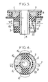
Les figures 5 et 6 montrent une autre variante de manchon antivibratoire conforme à l'invention, respectivement en coupe axiale selon V-V figure 6 et en coupe transversale selon VI-VI figure 5Figures 5 and 6 show another variant of the anti-vibration sleeve according to the invention, respectively in axial section along V-V in figure 6 and in cross section according to VI-VI in figure 5
Dans chaque cas le manchon comprend:
- une armature métallique tubulaire interne de révolution 1,
- une armature métallique tubulaire externe de
révolution 2 qui entoure l'armature 1 et qui, pour l'état de repos du manchon, est coaxiale à cette armature 1, l'axe commun X à ces deux armatures étant orienté verticalement, - et un corps en
élastomère 3 reliant l'une à l'autre les deux armatures 1 et 2 en ménageant entre celles-ci deux poches étanches A et B diamétralement opposées selon une direction horizontale Y.
- an internal tubular metal frame of revolution 1,
- an external tubular metallic frame of
revolution 2 which surrounds the frame 1 and which, for the state of rest of the sleeve, is coaxial with this frame 1, the axis X common to these two frames being oriented vertically, - and an
elastomer body 3 connecting the tworeinforcements 1 and 2 to each other, providing between them two sealed pockets A and B diametrically opposed in a horizontal direction Y.
L'armature interne 1 est destinée à être solidarisée avec une broche (non représentée) qui la traverse jointivement alors que l'armature externe 2 est destinée à être solidarisée avec un palier (non représenté), cette broche et ce palier étant solidaires respectivement des deux éléments rigides entre lesquels on désire monter un support antivibratoire, éléments tels qu'un train de suspension de véhicule et que le châssis ou caisse de ce véhicule.The internal frame 1 is intended to be secured with a pin (not shown) which passes through it contiguously while the
Les deux poches A et B sont réunies entre elles par un canal étroit 4 et ces deux poches ainsi que ce canal sont remplis d'un liquide amortisseur.The two pockets A and B are joined together by a narrow channel 4 and these two pockets and this channel are filled with a damping liquid.
Dans les modes de réalisation illustrés, le canal 4 est réalisé de la façon suivante.In the illustrated embodiments, channel 4 is produced in the following manner.
L'armature tubulaire interne 1 est composée de deux tronçons de tube, l'un intérieur 1₁ et l'autre extérieur 1₂ emmanchés jointivement l'un dans l'autre et le canal 4 est essentiellement constitué par une gorge semi-cylindrique 4₁ évidée dans la face cylindrique externe du tronçon tubulaire interne 1₁, cette gorge étant coiffée par la portion en regard de la face cylindrique interne du tronçon tubulaire externe 1₂ et ses deux extrémités sont raccordées à deux trous radiaux 4₂, diamétralement alignés, évidés dans le tronçon tubulaire externe 1₂ et débouchant respectivement dans les deux poches A et B.The internal tubular reinforcement 1 is made up of two sections of tube, one inside 1₁ and the other outside 1₂ fitted together one inside the other and the channel 4 is essentially constituted by a
La fixation du tronçon tubulaire intérieur 1₁ dans le tronçon tubulaire extérieur 1₂ est avantageusement effectuée par un effet de sertissage, en rabattant vers l'extérieur sur les extrémités du tronçon extérieur les extrémités amincies 20 du tronçon intérieur.The fixing of the inner
Avec un tel manchon, comme on le sait, les oscillations relatives appliquées selon la direction Y sur l'une des deux armatures tubulaires 1 et 2 se traduisent par des refoulements alternatifs du liquide amortisseur dans le canal 4 et, pour une valeur bien déterminée de la fréquence de ces oscillations, qui dépend essentiellement des cotes du canal 4, la colonne de liquide présente dans ce canal est mise en résonance et les débattements alternatifs qui en résultent ont pour effet d'empêcher ou tout au moins d'atténuer fortement la transmission des oscillations considérées entre les deux armatures.With such a sleeve, as is known, the relative oscillations applied in the direction Y on one of the two
Il peut être intéressant dans certains cas d'obtenir un amortissement du genre de celui qui vient d'être décrit non seulement selon la direction Y, mais également selon au moins une autre direction et en particulier selon la direction de l'axe X.It may be advantageous in certain cases to obtain a damping of the kind which has just been described not only in the direction Y, but also in at least one other direction and in particular along the direction of the axis X.
C'est par exemple le cas lorsqu'on désire amortir les mouvements relatifs, dits de "galop", appliqués sur certains trains de suspension de véhicules, et dont les trajectoires s'étendent selon des ellipses situées dans des plans verticaux longitudinaux de ces véhicules, et non selon de simples tronçons de droite verticaux.This is for example the case when it is desired to dampen the relative movements, known as "gallops", applied to certain suspension trains of vehicles, and the trajectories of which extend according to ellipses situated in longitudinal vertical planes of these vehicles. , and not in simple vertical straight sections.
A cet effet, on forme à l'extrémité axiale supérieure du manchon une chambre annulaire C délimitée intérieurement par un prolongement axial 5 de l'armature tubulaire interne 1, axialement par respectivement le corps en élastomère 3 et une collerette rigide 6 prolongeant radialement vers l'extérieur l'extrémité du prolongement 5, et extérieurement par une paroi élastique 7 résistante à la compression axiale, interposée axialement entre le bord de la collerette 6 et une autre collerette 8 prolongeant radialement vers l'extérieur l'extrémité correspondante de l'armature tubulaire externe 2.To this end, an annular chamber C is formed at the upper axial end of the sleeve, delimited internally by an
La paroi élastique 7 présente avantageusement une forme sensiblement cylindrique de révolution, avec au moins une rondelle de raidissement extérieure 9 venue de moulage avec elle.The
On prévoit en outre, conformément à l'invention, une chambre "de compensation", c'est-à-dire délimitée au moins en partie par une membrane flexible ou "soufflet" présentant une très faible résistance à la déformation, on relie la chambre annulaire C à cette chambre de compensation par un canal étroit et on remplit de liquide l'ensemble formé par ledit canal et par les deux chambres qu'il réunit.There is also provided, in accordance with the invention, a "compensation" chamber, that is to say bounded at least in part by a flexible membrane or "bellows" having a very low resistance to deformation, the annular chamber C to this compensation chamber by a narrow channel and one fills with liquid the assembly formed by said channel and by the two chambers which it joins.
Dans le premier mode de réalisation illustré sur les figures 1 et 2, la chambre de compensation est une chambre annulaire D prévue à l'extrémité axiale inférieure du manchon et délimitée intérieurement par un prolongement axial 10 de l'armature tubulaire interne 1, extérieurement par un prolongement axial 11 de l'armature tubulaire externe 2 et axialement par respectivement le corps en élastomère 3 et par la membrane flexible ou "soufflet" qui est ici annulaire et relie de façon étanche entre eux les deux prolongements 10 et 11.In the first embodiment illustrated in FIGS. 1 and 2, the compensation chamber is an annular chamber D provided at the lower axial end of the sleeve and delimited internally by an
Le canal étroit prévu pour relier entre elles les deux chambres annulaires C et D est ici désigné par la référence 13.The narrow channel intended to connect the two annular chambers C and D together is here designated by the
Dans le mode de réalisation illustré sur les dessins, le canal étroit 13 est constitué, comme le canal 4, par une rainure longitudinale évidée dans la face cylindrique externe du tronçon tubulaire interne 1₁ ci-dessus, les deux extrémités de cette rainure étant raccordées à deux lumières 14 évidées radialement dans le tronçon tubulaire externe 1₂ et débouchant respectivement dans les deux chambres C et D.In the embodiment illustrated in the drawings, the
Avec une telle construction, les oscillations relatives appliquées axialement sur l'une des armatures tubulaires 1 et 2 par rapport à l'autre se traduisent encore par des refoulements alternatifs de liquide dans le canal étroit 13 et, pour une valeur prédéterminée de la fréquence desdites oscillations, la colonne de liquide contenue dans ce canal est sujette à un effet de résonance qui assure une filtration efficace de ces oscillations.With such a construction, the relative oscillations applied axially on one of the
Cet amortissement "axial" est ici assuré d'une manière totalement indépendante de l'amortissement "radial" décrit ci-dessus, ce qui permet de régler avec précision chacun de ces deux comportements.This "axial" damping is here provided in a manner completely independent of the "radial" damping described above, which makes it possible to precisely adjust each of these two behaviors.
En outre, à la différence de ce que l'on observe pour les oscillations radiales ci-dessus, orientées selon la direction Y et faisant intervenir les deux poches identiques A et B, les deux chambres annulaires C et D ne jouent pas ici exactement le même rôle.In addition, unlike what is observed for the above radial oscillations, oriented in the direction Y and involving the two identical pockets A and B, the two annular chambers C and D do not play here exactly the same role.
Ici, seule la chambre C travaille véritablement, chaque compression axiale de sa paroi élastique 7 étant suivie par une dilatation axiale élastique de cette paroi : la chambre D, au contraire, ne fait qu'absorber passivement, sans réaction élastique, l'excédent de liquide, de volume variable, qui est chassé vers elle ou aspiré à partir d'elle à travers le canal 13.Here, only the chamber C actually works, each axial compression of its
Ce comportement, purement de "compensation", de la chambre annulaire D rend possible l'adoption de la caractéristique suivante.This behavior, purely of "compensation", of the annular chamber D makes it possible to adopt the following characteristic.
Pour augmenter le nombre des fréquences vis-à-vis desquelles l'amortissement du dispositif selon la direction Y est efficace, on prévoit au moins un canal étroit supplémentaire reliant l'une au moins des deux poches A et B à la chambre annulaire D, et de préférence deux tels canaux 15, 16 affectés respectivement à ces deux poches.To increase the number of frequencies vis-à-vis which the damping of the device in the direction Y is effective, at least one additional narrow channel is provided, connecting at least one of the two pockets A and B to the annular chamber D, and preferably two
Cette mesure peut être adoptée sans remettre en cause la totale indépendance entre les deux amortissements exercés respectivement selon les deux directions X et Y du fait que la chambre D est une chambre de compensation ne faisant qu'absorber passivement les excédents variables de liquide qui lui sont envoyés sans appliquer aucune réaction élastique sur ces excédents.This measure can be adopted without calling into question the total independence between the two amortizations exercised respectively in the two directions X and Y owing to the fact that the chamber D is a compensation chamber only passively absorbing the variable surpluses of liquid which are given to it sent without applying any elastic reaction to these surpluses.
Ici encore, et comme pour les canaux précédents 4 et 13, les canaux 15 et 16 sont avantageusement matérialisés par des gorges évidées dans le tronçon tubulaire interne 1₁, tronçon coiffé par des portions en regard de la surface cylindrique interne du tronçon tubulaire externe 1₂ et communiquant avec les poches A et B et la chambre D à travers des lumières radiales évidées dans ledit tronçon tubulaire externe.Here again, and as for the preceding
Si l'on désire multiplier les fréquences des oscillations vis-à-vis desquelles le manchon est en mesure d'assurer un bon amortissement selon la direction axiale, on peut également multiplier le nombre des canaux étroits reliant entre elles les deux chambres annulaires C et D, éventuellement en divisant l'une au moins de ces deux chambres en au moins deux compartiments distincts reliés respectivement, soit à l'autre chambre, non subdivisée, soit respectivement à des compartiments eux-mêmes subdivisés de cette autre chambre.If it is desired to multiply the frequencies of the oscillations with respect to which the sleeve is able to ensure good damping in the axial direction, it is also possible to multiply the number of narrow channels connecting the two annular chambers C and D, possibly by dividing at least one of these two chambers into at least two separate compartments connected respectively, either to the other chamber, not subdivided, or respectively to compartments themselves subdivided from this other chamber.
En suite de quoi et quel que soit le mode de réalisation adopté, on dispose finalement d'un manchon amortisseur dont la constitution, le fonctionnement et les avantages (en particulier la possibilité d'assurer un amortissement efficace "bidirectionnel", c'est-à-dire selon deux directions X et Y perpendiculaires entre elles) résultent suffisamment de ce qui précède.As a result of what and whatever the embodiment adopted, there is finally a shock-absorbing sleeve whose constitution, operation and advantages (in particular the possibility of ensuring effective "two-way" damping, that is, that is to say in two directions X and Y perpendicular to each other) result sufficiently from the above.
Comme il va de soi, et comme il résulte d'ailleurs déjà de ce qui précède, l'invention ne se limite nullement à ceux de ses modes d'application et de réalisation qui ont été plus spécialement envisagés ; elle en embrasse, au contraire, toutes les variantes, notamment:
- celles où le manchon considéré permettrait d'assurer un amortissement efficace non seulement "bidirectionnel", mais "tridirectionnel" ou "universel", c'est-à-dire selon trois directions X, Y et Z perpendiculaires entre elles,
- et celles où la chambre "de compensation" ci-dessus serait constituée par l'une des deux poches diamétralement opposées du manchon.
- those where the sleeve considered would ensure effective damping not only "bidirectional", but "tridirectional" or "universal", that is to say in three directions X, Y and Z perpendicular to each other,
- and those where the above "compensation" chamber would be constituted by one of the two diametrically opposite pockets of the sleeve.
La première de ces deux variantes est illustrée sur les figures 3 et 4.The first of these two variants is illustrated in Figures 3 and 4.
Selon celle-ci, on remplace les deux chambres A et B diamétralement opposées selon la direction Y par quatre chambres A, B, E et F réparties régulièrement ou non autour de l'axe X et diamétralement opposées deux à deux, savoir les deux chambres A et B selon la direction Y et les deux chambres C et D selon la direction Z, perpendiculaire aux deux directions X et Y, et on relie diamétralement ces chambres deux à deux à l'aide de canaux étroits du genre du canal 4 ci-dessus, ce canal 4 reliant les deux poches A et B et un autre canal du même type 17 reliant entre elles les deux poches E et F.According to this, the two chambers A and B diametrically opposed in the direction Y are replaced by four chambers A, B, E and F distributed regularly or not around the X axis and diametrically opposite in pairs, namely the two chambers A and B in the direction Y and the two chambers C and D in the direction Z, perpendicular to the two directions X and Y, and these diametrically are connected chambers two by two using narrow channels of the type of channel 4 above, this channel 4 connecting the two pockets A and B and another channel of the
Chacune de ces quatre poches A, B, E et F peut être reliée à la chambre annulaire D par un canal étroit du genre des canaux 15 et 16 ci-dessus, ces canaux étant désignés respectivement par les références 18 et 19 sur la figure 4.Each of these four pockets A, B, E and F can be connected to the annular chamber D by a narrow channel like the
Comme on le voit sur cette figure, il faut bien entendu éviter que les différents canaux se croisent, ce qui conduit à prévoir pour certains d'entre eux des détours leur permettant de contourner les autres canaux.As can be seen in this figure, it is of course necessary to avoid the different channels crossing, which leads to providing for some of them detours allowing them to bypass the other channels.
On peut tirer parti de ces détours pour donner à certains des canaux en question une relativement grande longueur, comme il est recherché pour certaines applications.We can take advantage of these detours to give some of the channels in question a relatively long length, as is sought for certain applications.
Avec une telle variante, on peut assurer un amortissement efficace selon toutes les directions de l'espace, car n'importe quelle direction peut être décomposée en ses trois composantes orientées respectivement selon les trois directions X, Y et Z, et la multiplicité des canaux ci-dessus décrits, associée à la nature purement "compensatoire" de la chambre D dans laquelle débouchent le plupart d'entre eux, permettent d'adapter indépendamment le manchon à l'amortissement de plusieurs types d'oscillations appliquées sur celui-ci selon des directions distinctes.With such a variant, effective damping can be ensured in all directions of space, since any direction can be broken down into its three components oriented respectively in the three directions X, Y and Z, and the multiplicity of channels described above, associated with the purely "compensatory" nature of the chamber D into which most of them open, make it possible to independently adapt the sleeve to the damping of several types of oscillations applied to it according to separate directions.
La seconde des deux variantes indiquées ci-dessus est illustrée sur les figures 5 et 6.The second of the two variants indicated above is illustrated in Figures 5 and 6.
Selon celle-ci, la poche B ci-dessus est constituée par une poche B′ limitée extérieurement par l'armature tubulaire externe 2 et intérieurement par un soufflet flexible 21 lui-même constitué par un bandeau mince et incurvé à la fois transversalement selon un dos d'âne bombé vers l'axe X et longitudinalement selon un croissant sensiblement parallèle à l'armature 2, ce bandeau délimitant un alvéole 22 axialement creusé dans la face frontale inférieure du manchon.According to this, the pocket B above is constituted by a pocket B ′ externally limited by the external
C'est ici dans cette poche B′ que débouche le canal étroit 13′ relié à la chambre annulaire C.It is here in this pocket B ′ that the
Pour rendre possible sur deux fréquences d'oscillation différentes le réglage de l'amortissement selon la direction radiale Y, on a en outre ici divisé en deux compartiments la poche qui est diamétralement opposée à la poche B′, ces deux compartiments étant désignés par les références A′₁ et A′₂ et étant reliés respectivement à la poche B′ par deux canaux étroits 4′₁ et 4′₂ de cotes différentes.To make it possible on two different oscillation frequencies to adjust the damping in the radial direction Y, the pocket which is diametrically opposite to the pocket B ′ is further divided here into two compartments, these two compartments being designated by the references A′₁ and A′₂ and being connected respectively to the pocket B ′ by two narrow channels 4′₁ and 4′₂ of different dimensions.
Les trois canaux 13′, 4′₁ et 4′₂ ont été représentés par des flèches sur les figures 5 et 6.The three
Ils sont ici ménagés à proximité de l'armature tubulaire 2, d'une façon connue en soi, chacun de ces canaux pouvant être matérialisé par une gorge évidée dans la face extérieure d'une douille cylindrique logée jointivement à l'intérieur de l'armature tubulaire externe 2, cette gorge étant coiffée par cette armature et reliée à ses deux extrémités à des lumières appropriées évidées dans ladite douille et débouchant dans les poches ou chambres concernéesThey are here provided near the
Le fonctionnement du manchon selon la présente variante se déduit facilement de ceux décrits précédemment à propos des autres variantes.The operation of the sleeve according to the present variant is easily deduced from those described above with regard to the other variants.
Il est à noter, que, ici encore, les amortissements assurés respectivement selon les deux directions X et Y peuvent être réglés indépendamment l'un de l'autre, vu le type "de compensation" qui est adopté pour la poche B′ dans laquelle débouchent la totalité des canaux étroits 13′, 4′₁ et 4′₂.It should be noted that, here again, the depreciation provided respectively in the two directions X and Y can be adjusted independently of one another, given the type of "compensation" which is adopted for the pocket B ′ in which open all of the
Claims (7)
Applications Claiming Priority (2)
| Application Number | Priority Date | Filing Date | Title |
|---|---|---|---|
| FR9003416A FR2659712B1 (en) | 1990-03-16 | 1990-03-16 | IMPROVEMENTS TO HYDRAULIC ANTI-VIBRATION SLEEVES. |
| FR9003416 | 1990-03-16 |
Publications (2)
| Publication Number | Publication Date |
|---|---|
| EP0452169A1 true EP0452169A1 (en) | 1991-10-16 |
| EP0452169B1 EP0452169B1 (en) | 1994-04-27 |
Family
ID=9394834
Family Applications (1)
| Application Number | Title | Priority Date | Filing Date |
|---|---|---|---|
| EP91400686A Expired - Lifetime EP0452169B1 (en) | 1990-03-16 | 1991-03-13 | Improvements to hydraulic anti-vibration bushes |
Country Status (4)
| Country | Link |
|---|---|
| US (1) | US5172893A (en) |
| EP (1) | EP0452169B1 (en) |
| DE (1) | DE69101803T2 (en) |
| FR (1) | FR2659712B1 (en) |
Cited By (16)
| Publication number | Priority date | Publication date | Assignee | Title |
|---|---|---|---|---|
| EP0438559A1 (en) * | 1989-07-18 | 1991-07-31 | Lord Corporation | Three-axis fluid-filled mount |
| EP0577916A1 (en) * | 1992-07-09 | 1994-01-12 | Firma Carl Freudenberg | Hydraulically-damped elastomeric support |
| EP0636810A1 (en) * | 1993-07-29 | 1995-02-01 | Hutchinson | Improvement for damping supports of helicopter rotor blades and helicopter rotor with such supports |
| DE4438932A1 (en) * | 1994-10-31 | 1996-05-02 | Daimler Benz Ag | Hydro bearing |
| FR2735833A1 (en) * | 1995-06-23 | 1996-12-27 | Tokai Rubber Ind Ltd | FLUID-FILLED CUSHIONING DEVICE WITH HIGH ELASTIC RIGIDITY IN TWO MUTUALLY PERPENDICULAR DIRECTIONS |
| FR2736890A1 (en) * | 1995-07-18 | 1997-01-24 | Eurocopter France | Helicopter rotor blade hydro-elastic damper, mounted between rotor blade and hub - has external tubular casing with coaxial rod supported by elastomer sleeves, piston between sleeves delimiting two hydraulic fluid chambers communicating through laminar flow passage |
| EP0775844A2 (en) * | 1995-11-20 | 1997-05-28 | WOCO Franz-Josef Wolf & Co. | Support |
| GB2368381A (en) * | 2000-10-04 | 2002-05-01 | Mannesmann Boge Gmbh | A hydraulically damped rubber mounting |
| WO2005059399A1 (en) * | 2003-12-16 | 2005-06-30 | Zf Friedrichshafen Ag | Switchable hydraulically damping bush bearing |
| EP1870613A1 (en) * | 2005-04-12 | 2007-12-26 | Bridgestone Corporation | Vibration isolator |
| US7441757B2 (en) | 2003-12-16 | 2008-10-28 | Zf Friedrichshafen Ag | Hydraulically damping bush bearing |
| WO2014019784A1 (en) * | 2012-07-31 | 2014-02-06 | Zf Friedrichshafen Ag | Hydraulically damping bush bearing |
| EP2604884A3 (en) * | 2011-12-12 | 2014-04-30 | Carl Freudenberg KG | Hydromount and use of same |
| US9903438B2 (en) | 2012-07-31 | 2018-02-27 | Boge Elastmetall Gmbh | Hydraulically damping bush bearing |
| CN109094315A (en) * | 2018-08-16 | 2018-12-28 | 安徽奥丰汽车配件有限公司 | A kind of automobile chassis combination rubber bushing |
| EP4023904A4 (en) * | 2019-08-30 | 2023-11-01 | Zhuzhou Times Ruiwei Anti-Viberation Equipment Limited | Method for forming liquid rubber composite node having pipe flow channel |
Families Citing this family (44)
| Publication number | Priority date | Publication date | Assignee | Title |
|---|---|---|---|---|
| JP3123237B2 (en) * | 1992-07-01 | 2001-01-09 | 豊田合成株式会社 | Liquid filled vibration isolator |
| US5374039A (en) * | 1992-08-24 | 1994-12-20 | Lord Corporation | Fluid-and-elastomer support device |
| AU708360B2 (en) | 1994-09-15 | 1999-08-05 | C.R. Bard Inc. | Hooked endoprosthesis |
| DE19515838C2 (en) * | 1995-04-29 | 1998-04-16 | Freudenberg Carl Fa | Hydraulically damping rubber bearing |
| IT1285032B1 (en) * | 1996-03-25 | 1998-06-03 | F I B E T S P A | GUIDE MECHANICAL CONNECTION DEVICE WITH AXIAL AND RADIAL ELASTIC LOCK WITH TORSIONAL RELEASE, IN PARTICULAR FOR |
| DE19622248C2 (en) * | 1996-06-04 | 1999-02-18 | Freudenberg Carl Fa | Hydraulically damping sleeve rubber spring |
| US6430774B1 (en) | 1999-07-02 | 2002-08-13 | The Pullman Company | Crimped bushing |
| US6755403B2 (en) | 1999-09-29 | 2004-06-29 | The Pullman Company | Non-slip sta-bar bushing |
| DE10037954B4 (en) * | 2000-05-30 | 2012-01-19 | Carl Freudenberg Kg | hydromount |
| DE10035024A1 (en) * | 2000-07-19 | 2002-01-31 | Daimler Chrysler Ag | Hydraulically damped elastomer bearing for vehicle comprises flexible block connecting coaxial outer and inner sleeves, chambers enclosed between block and inner sleeve being filled with damping fluid and connected by throttle channels |
| DE10035025A1 (en) * | 2000-07-19 | 2002-01-31 | Daimler Chrysler Ag | Hydraulically damping elastomer bearing |
| US6651768B2 (en) * | 2000-11-06 | 2003-11-25 | Bombardier Inc. | Snowmobile engine mount |
| EP1887250B1 (en) * | 2001-04-10 | 2012-01-11 | Yamashita Rubber Kabushiki Kaisha | Fluid-sealed anti-vibration device |
| JP4545343B2 (en) * | 2001-04-10 | 2010-09-15 | 山下ゴム株式会社 | Liquid seal vibration isolator |
| DE10200764A1 (en) * | 2002-01-10 | 2003-08-07 | Woco Franz Josef Wolf & Co Gmbh | Air suspension bearing with three axles |
| GB0205020D0 (en) * | 2002-03-04 | 2002-04-17 | Avon Vibration Man Syst Ltd | Hydraulically damped mounting device |
| DE10251877B4 (en) * | 2002-11-07 | 2008-08-07 | Trelleborg Automotive Technical Centre Gmbh | Hydraulically damping bearing, in particular for supporting the engine of a motor vehicle |
| JP3858908B2 (en) * | 2004-03-30 | 2006-12-20 | 東海ゴム工業株式会社 | Engine mount |
| JP4217686B2 (en) * | 2004-09-29 | 2009-02-04 | 株式会社ブリヂストン | Vibration isolator |
| FR2876428B1 (en) * | 2004-10-11 | 2008-08-08 | Hutchinson Sa | ANTI-VIBRATION DEVICE AND VEHICLE COMPRISING SUCH A DEVICE |
| FR2876429B1 (en) * | 2004-10-11 | 2007-02-23 | Hutchinson Sa | HYDRAULIC ANTI-VIBRATION DEVICE FOR A VEHICLE AND METHOD OF MANUFACTURING SUCH A DEVICE |
| JP4602821B2 (en) * | 2005-04-04 | 2010-12-22 | 株式会社ブリヂストン | Vibration isolator |
| JP4528661B2 (en) * | 2005-04-06 | 2010-08-18 | 株式会社ブリヂストン | Vibration isolator |
| JP4939997B2 (en) * | 2006-04-05 | 2012-05-30 | 株式会社ブリヂストン | Vibration isolator |
| EP2006570B1 (en) * | 2006-04-07 | 2013-09-04 | Bridgestone Corporation | Vibration damper |
| US8177201B2 (en) * | 2006-07-19 | 2012-05-15 | The Pullman Company | Very high damping mount with bolt-through construction |
| US8231115B2 (en) * | 2006-07-19 | 2012-07-31 | The Pullman Company | Very high damping body mount, subframe mount or engine mount with bolt-through construction |
| US7637486B2 (en) * | 2006-07-19 | 2009-12-29 | The Pullman Company | Very high damping body mount, subframe mount or engine mount with bolt-through construction |
| US9494210B2 (en) * | 2006-08-04 | 2016-11-15 | Honda Motor Co., Ltd. | Vehicle mount and method |
| US8267383B2 (en) * | 2008-07-28 | 2012-09-18 | Honda Motor Company, Ltd. | Mount devices and methods for measuring force |
| JP2010159873A (en) * | 2008-12-09 | 2010-07-22 | Tokai Rubber Ind Ltd | Cylindrical vibration isolating device of fluid encapsulation type |
| WO2011084134A1 (en) * | 2009-12-16 | 2011-07-14 | Goudie Robert J | Hydraulic body mount |
| JP5678073B2 (en) * | 2010-09-22 | 2015-02-25 | 株式会社ブリヂストン | Vibration isolator |
| DE102013201444A1 (en) * | 2013-01-30 | 2014-07-31 | Zf Friedrichshafen Ag | Biaxial absorbing hydraulic bearing for connecting constructive components in automotive industry, has radially acting damping device in fluid communication with axially acting damping device through hydraulic damping fluid |
| DE102013209990A1 (en) * | 2013-05-29 | 2014-12-04 | Zf Friedrichshafen Ag | Hydraulically damping rubber mount |
| CN104421339B (en) * | 2013-08-19 | 2017-08-22 | 广州汽车集团股份有限公司 | A kind of self-lubricating rubber bushing and automobile suspension system guider |
| JP6595257B2 (en) * | 2015-08-24 | 2019-10-23 | 株式会社ブリヂストン | Vibration isolator |
| DE102016015710B4 (en) * | 2016-02-10 | 2020-04-02 | Anvis Deutschland Gmbh | Vibration damper |
| DE102016001507B4 (en) * | 2016-02-10 | 2020-06-18 | Anvis Deutschland Gmbh | Vibration damper |
| DE102016212485B4 (en) * | 2016-07-08 | 2018-01-18 | Contitech Vibration Control Gmbh | Rifle |
| JP6877227B2 (en) | 2017-04-17 | 2021-05-26 | 株式会社ブリヂストン | Anti-vibration device |
| JP2018204774A (en) * | 2017-06-09 | 2018-12-27 | 株式会社ブリヂストン | Vibration controller |
| US11187047B1 (en) * | 2017-06-26 | 2021-11-30 | Hrl Laboratories, Llc | Multi-degree of freedom vibration isolator |
| DE102018006081B4 (en) * | 2018-08-01 | 2020-12-17 | Sumitomo Riko Company Limited | Hydraulic damping bearing and method for providing a hydraulic damping bearing |
Family Cites Families (7)
| Publication number | Priority date | Publication date | Assignee | Title |
|---|---|---|---|---|
| DE3130830A1 (en) * | 1981-08-04 | 1983-02-24 | WOCO Franz-Josef Wolf & Co, 6483 Bad Soden-Salmünster | SPRING ELEMENT AND ITS USE |
| JPS5937349A (en) * | 1982-08-23 | 1984-02-29 | Tokai Rubber Ind Ltd | Vibration preventing support |
| JPS5943239A (en) * | 1982-09-06 | 1984-03-10 | Tokai Rubber Ind Ltd | Cushion rubber device |
| JPS629041A (en) * | 1985-07-05 | 1987-01-17 | Toyota Motor Corp | Vibration absorbing rubber device |
| JPH0519631Y2 (en) * | 1985-11-28 | 1993-05-24 | ||
| JPS63266240A (en) * | 1987-04-23 | 1988-11-02 | Mazda Motor Corp | Fluid-filled bush |
| FR2616868B1 (en) * | 1987-06-19 | 1989-10-27 | Hutchinson | IMPROVEMENTS ON HYDRAULIC ANTI-VIBRATION SUPPORT SLEEVES |
-
1990
- 1990-03-16 FR FR9003416A patent/FR2659712B1/en not_active Expired - Fee Related
-
1991
- 1991-03-13 DE DE69101803T patent/DE69101803T2/en not_active Expired - Fee Related
- 1991-03-13 EP EP91400686A patent/EP0452169B1/en not_active Expired - Lifetime
- 1991-03-14 US US07/669,885 patent/US5172893A/en not_active Expired - Fee Related
Non-Patent Citations (2)
| Title |
|---|
| PATENT ABSTRACTS OF JAPAN, vol. 8, no. 140 (M-305)[1577] 29 juin 1984; & JP-A-59 037 349 (TOUKAI GOMU KOGYO KK) 29 février 1984, * |
| PATENT ABSTRACTS OF JAPAN, vol. 8, no. 146 (M-307)[1583] 07 juillet 1984; & JP-A-59 043 239 (TOUKAI GOMU KOGYO KK) 10 mars 1984, * |
Cited By (29)
| Publication number | Priority date | Publication date | Assignee | Title |
|---|---|---|---|---|
| EP0438559A1 (en) * | 1989-07-18 | 1991-07-31 | Lord Corporation | Three-axis fluid-filled mount |
| EP0438559A4 (en) * | 1989-07-18 | 1993-04-21 | Thorn, Richard P. | Three-axis fluid-filled mount |
| EP0577916A1 (en) * | 1992-07-09 | 1994-01-12 | Firma Carl Freudenberg | Hydraulically-damped elastomeric support |
| EP0636810A1 (en) * | 1993-07-29 | 1995-02-01 | Hutchinson | Improvement for damping supports of helicopter rotor blades and helicopter rotor with such supports |
| FR2708694A1 (en) * | 1993-07-29 | 1995-02-10 | Hutchinson | Improvement to anti-vibration supports. |
| US5489193A (en) * | 1993-07-29 | 1996-02-06 | Hutchinson | Antivibration supports for helicopter blades, and a helicopter rotor including such supports |
| DE4438932A1 (en) * | 1994-10-31 | 1996-05-02 | Daimler Benz Ag | Hydro bearing |
| US5531426A (en) * | 1994-10-31 | 1996-07-02 | Mercedes-Benz Ag | Hydraulic support |
| DE4438932C2 (en) * | 1994-10-31 | 1998-07-02 | Daimler Benz Ag | Hydro bearing |
| FR2735833A1 (en) * | 1995-06-23 | 1996-12-27 | Tokai Rubber Ind Ltd | FLUID-FILLED CUSHIONING DEVICE WITH HIGH ELASTIC RIGIDITY IN TWO MUTUALLY PERPENDICULAR DIRECTIONS |
| US5690320A (en) * | 1995-06-23 | 1997-11-25 | Tokai Rubber Industries, Ltd. | Fluid-filled damping device having a large spring stiffness values in two mutually perpendicular diametric directions |
| FR2736890A1 (en) * | 1995-07-18 | 1997-01-24 | Eurocopter France | Helicopter rotor blade hydro-elastic damper, mounted between rotor blade and hub - has external tubular casing with coaxial rod supported by elastomer sleeves, piston between sleeves delimiting two hydraulic fluid chambers communicating through laminar flow passage |
| EP0775844A2 (en) * | 1995-11-20 | 1997-05-28 | WOCO Franz-Josef Wolf & Co. | Support |
| EP0775844A3 (en) * | 1995-11-20 | 1999-06-02 | WOCO Franz-Josef Wolf & Co. | Support |
| GB2368381A (en) * | 2000-10-04 | 2002-05-01 | Mannesmann Boge Gmbh | A hydraulically damped rubber mounting |
| US7392976B2 (en) | 2003-12-16 | 2008-07-01 | Zf Friedrichshafen Ag | Switchable hydraulically damping bush bearing |
| US7441757B2 (en) | 2003-12-16 | 2008-10-28 | Zf Friedrichshafen Ag | Hydraulically damping bush bearing |
| WO2005059399A1 (en) * | 2003-12-16 | 2005-06-30 | Zf Friedrichshafen Ag | Switchable hydraulically damping bush bearing |
| EP1870613A1 (en) * | 2005-04-12 | 2007-12-26 | Bridgestone Corporation | Vibration isolator |
| EP1870613A4 (en) * | 2005-04-12 | 2011-04-13 | Bridgestone Corp | Vibration isolator |
| US8297602B2 (en) | 2005-04-12 | 2012-10-30 | Bridgestone Corporation | Vibration isolator |
| EP2604884A3 (en) * | 2011-12-12 | 2014-04-30 | Carl Freudenberg KG | Hydromount and use of same |
| WO2014019784A1 (en) * | 2012-07-31 | 2014-02-06 | Zf Friedrichshafen Ag | Hydraulically damping bush bearing |
| CN104781576A (en) * | 2012-07-31 | 2015-07-15 | 伯杰橡胶金属有限责任公司 | Hydraulically damping bush bearing |
| US9528566B2 (en) | 2012-07-31 | 2016-12-27 | Audi Ag | Hydraulically damping bush bearing |
| CN104781576B (en) * | 2012-07-31 | 2017-06-06 | 伯杰橡胶金属有限责任公司 | The sleeve bearing of liquid-springing |
| US9903438B2 (en) | 2012-07-31 | 2018-02-27 | Boge Elastmetall Gmbh | Hydraulically damping bush bearing |
| CN109094315A (en) * | 2018-08-16 | 2018-12-28 | 安徽奥丰汽车配件有限公司 | A kind of automobile chassis combination rubber bushing |
| EP4023904A4 (en) * | 2019-08-30 | 2023-11-01 | Zhuzhou Times Ruiwei Anti-Viberation Equipment Limited | Method for forming liquid rubber composite node having pipe flow channel |
Also Published As
| Publication number | Publication date |
|---|---|
| EP0452169B1 (en) | 1994-04-27 |
| DE69101803T2 (en) | 1994-11-24 |
| FR2659712B1 (en) | 1992-07-17 |
| US5172893A (en) | 1992-12-22 |
| DE69101803D1 (en) | 1994-06-01 |
| FR2659712A1 (en) | 1991-09-20 |
Similar Documents
| Publication | Publication Date | Title |
|---|---|---|
| EP0452169B1 (en) | Improvements to hydraulic anti-vibration bushes | |
| EP0296062B1 (en) | Hydraulic antivibration mounts of the bushing type | |
| EP0335786B1 (en) | Elastic strut with an integrated hydro-mechanic resonator, in particilar for the suspension of a gear box on a rotorplane, and a suspension device comprising such an application | |
| EP0306369B1 (en) | Hydraulically damped bushings | |
| EP0223712B1 (en) | Modifications of hydraulic dampers | |
| EP0359655B1 (en) | Hydraulically damped bushings | |
| EP0479654B1 (en) | Improvements to hydraulic anti-vibration bushings and to damping arrangements using such bushings | |
| EP0486369B1 (en) | Hydraulic anti-vibration bush | |
| EP0721071A1 (en) | Improvements to antivibratory hydraulic supports | |
| EP0278824B1 (en) | Hydraulic antivibration mountings | |
| EP0255434A1 (en) | Hydraulic damping mountings | |
| EP0437137A1 (en) | Bush-type hydraulic vibration dampers | |
| EP0411997A1 (en) | Modifications of bush-type hydraulic vibration dampers | |
| FR2655113A1 (en) | ELASTOMER DAMPING DEVICE FILLED WITH A FLUID. | |
| FR2659713A1 (en) | Improvements to hydraulic anti-vibration sleeves | |
| EP0957286B1 (en) | Hydroelastic support for the suspension of an automotive vehicle drive unit to the vehicle body | |
| EP0798487B1 (en) | Hydraulic antivibration mounts of the bushing type | |
| EP3619444B1 (en) | Hydroelastic device comprising a locking system | |
| EP0539282B1 (en) | Improvements to hydraulic anti-vibration mountings | |
| EP2464889B1 (en) | Hydroelastic joint | |
| FR2657666A1 (en) | Improvements to hydraulic anti-vibration devices | |
| FR2747166A1 (en) | Hydraulic anti=vibration support sleeve for suspension units on motor vehicles | |
| FR2605693A1 (en) | Improvements to anti-vibration hydraulic supports | |
| EP4040005A1 (en) | Anti-vibration support and vehicle comprising such an anti-vibration support | |
| FR2814521A1 (en) | Hydroelastic engine mounting comprises rigid casing and a rigid internal frame connected by elastomeric molding in which intermediate frame with annular flanges connected by spacer plates is embedded and which encloses working chamber |
Legal Events
| Date | Code | Title | Description |
|---|---|---|---|
| PUAI | Public reference made under article 153(3) epc to a published international application that has entered the european phase |
Free format text: ORIGINAL CODE: 0009012 |
|
| AK | Designated contracting states |
Kind code of ref document: A1 Designated state(s): DE GB SE |
|
| 17P | Request for examination filed |
Effective date: 19911209 |
|
| 17Q | First examination report despatched |
Effective date: 19930210 |
|
| GRAA | (expected) grant |
Free format text: ORIGINAL CODE: 0009210 |
|
| AK | Designated contracting states |
Kind code of ref document: B1 Designated state(s): DE GB SE |
|
| PG25 | Lapsed in a contracting state [announced via postgrant information from national office to epo] |
Ref country code: SE Free format text: THE PATENT HAS BEEN ANNULLED BY A DECISION OF A NATIONAL AUTHORITY Effective date: 19940427 |
|
| REF | Corresponds to: |
Ref document number: 69101803 Country of ref document: DE Date of ref document: 19940601 |
|
| GBT | Gb: translation of ep patent filed (gb section 77(6)(a)/1977) |
Effective date: 19940505 |
|
| PLBE | No opposition filed within time limit |
Free format text: ORIGINAL CODE: 0009261 |
|
| STAA | Information on the status of an ep patent application or granted ep patent |
Free format text: STATUS: NO OPPOSITION FILED WITHIN TIME LIMIT |
|
| 26N | No opposition filed | ||
| PGFP | Annual fee paid to national office [announced via postgrant information from national office to epo] |
Ref country code: GB Payment date: 19990305 Year of fee payment: 9 |
|
| PGFP | Annual fee paid to national office [announced via postgrant information from national office to epo] |
Ref country code: DE Payment date: 19990317 Year of fee payment: 9 |
|
| PG25 | Lapsed in a contracting state [announced via postgrant information from national office to epo] |
Ref country code: GB Free format text: LAPSE BECAUSE OF NON-PAYMENT OF DUE FEES Effective date: 20000313 |
|
| GBPC | Gb: european patent ceased through non-payment of renewal fee |
Effective date: 20000313 |
|
| PG25 | Lapsed in a contracting state [announced via postgrant information from national office to epo] |
Ref country code: DE Free format text: LAPSE BECAUSE OF NON-PAYMENT OF DUE FEES Effective date: 20010103 |