EP0636810A1 - Improvement for damping supports of helicopter rotor blades and helicopter rotor with such supports - Google Patents
Improvement for damping supports of helicopter rotor blades and helicopter rotor with such supports Download PDFInfo
- Publication number
- EP0636810A1 EP0636810A1 EP94401730A EP94401730A EP0636810A1 EP 0636810 A1 EP0636810 A1 EP 0636810A1 EP 94401730 A EP94401730 A EP 94401730A EP 94401730 A EP94401730 A EP 94401730A EP 0636810 A1 EP0636810 A1 EP 0636810A1
- Authority
- EP
- European Patent Office
- Prior art keywords
- axis
- rigid
- pockets
- deformable
- frame
- Prior art date
- Legal status (The legal status is an assumption and is not a legal conclusion. Google has not performed a legal analysis and makes no representation as to the accuracy of the status listed.)
- Granted
Links
Images

Classifications
-
- B—PERFORMING OPERATIONS; TRANSPORTING
- B64—AIRCRAFT; AVIATION; COSMONAUTICS
- B64C—AEROPLANES; HELICOPTERS
- B64C27/00—Rotorcraft; Rotors peculiar thereto
- B64C27/51—Damping of blade movements
-
- F—MECHANICAL ENGINEERING; LIGHTING; HEATING; WEAPONS; BLASTING
- F16—ENGINEERING ELEMENTS AND UNITS; GENERAL MEASURES FOR PRODUCING AND MAINTAINING EFFECTIVE FUNCTIONING OF MACHINES OR INSTALLATIONS; THERMAL INSULATION IN GENERAL
- F16F—SPRINGS; SHOCK-ABSORBERS; MEANS FOR DAMPING VIBRATION
- F16F13/00—Units comprising springs of the non-fluid type as well as vibration-dampers, shock-absorbers, or fluid springs
- F16F13/04—Units comprising springs of the non-fluid type as well as vibration-dampers, shock-absorbers, or fluid springs comprising both a plastics spring and a damper, e.g. a friction damper
- F16F13/06—Units comprising springs of the non-fluid type as well as vibration-dampers, shock-absorbers, or fluid springs comprising both a plastics spring and a damper, e.g. a friction damper the damper being a fluid damper, e.g. the plastics spring not forming a part of the wall of the fluid chamber of the damper
- F16F13/08—Units comprising springs of the non-fluid type as well as vibration-dampers, shock-absorbers, or fluid springs comprising both a plastics spring and a damper, e.g. a friction damper the damper being a fluid damper, e.g. the plastics spring not forming a part of the wall of the fluid chamber of the damper the plastics spring forming at least a part of the wall of the fluid chamber of the damper
Abstract
Description
L'invention concerne les supports antivibratoires de pales d'hélicoptère, et plus particulièrement les dispositifs antivibratoires pour le montage de pales d'hélicoptères, ces dispositifs comportant :
- une première et une deuxième armatures rigides solidarisables respectivement avec deux éléments rigides à réunir, chaque armature présentant une face d'appui dirigée vers l'autre armature rigide, les deux faces d'appui étant disposées en regard l'une de l'autre et perpendiculairement à un premier axe Z,
- et au moins un élément lamifié interposé entre les deux faces d'appui, ledit élément lamifié présentant deux faces opposées qui sont solidaires respectivement des deux faces d'appui, ledit élément lamifié étant constitué de couches alternées de matériau rigide et d'élastomère qui sont disposées perpendiculairement au premier axe Z, ledit élément lamifié permettant, par sa déformation, un déplacement relatif des deux armatures selon un deuxième axe Y perpendiculaire au premier axe Z.
- first and second rigid reinforcements which can be joined together respectively with two rigid elements to be joined, each reinforcement having a bearing face directed towards the other rigid reinforcement, the two bearing faces being arranged opposite one another and perpendicular to a first Z axis,
- and at least one laminated element interposed between the two support faces, said laminated element having two opposite faces which are integral respectively with the two support faces, said laminated element consisting of alternating layers of rigid material and of elastomer which are arranged perpendicular to the first axis Z, said laminated element allowing, by its deformation, a relative displacement of the two reinforcements along a second axis Y perpendicular to the first axis Z.
Ainsi, les deux armatures rigides ne peuvent quasiment pas se déplacer l'une par rapport à l'autre selon le premier axe Z du fait de la grande raideur de l'élément lamifié parallèlement à l'axe Z, tandis que leur mouvement relatif est possible parallèlement au deuxième axe Y. L'axe Z est orthogonal aux pales du rotor.Thus, the two rigid reinforcements can hardly move relative to each other along the first axis Z due to the great stiffness of the laminated element parallel to the axis Z, while their relative movement is possible parallel to the second Y axis. The Z axis is orthogonal to the rotor blades.
Dans ces dispositifs, il est souhaitable d'amortir au maximum les mouvements vibratoires ou oscillations relatifs des armatures parallèlement au deuxième axe Y.In these devices, it is desirable to dampen to the maximum the vibratory movements or relative oscillations of the armatures parallel to the second axis Y.
Une solution connue de ce problème technique est d'utiliser dans les couches élastomères de l'élément lamifié, un élastomère au silicone, plus amortisseur que les élastomères classiques et qui apporte à la fois la raideur et l'amortissement souhaités.A known solution to this technical problem is to use in the elastomeric layers of the laminated element, a silicone elastomer, more damping than conventional elastomers and which provides both stiffness and desired depreciation.
Toutefois, avec de tels éléments lamifiés, l'obtention d'un niveau d'amortissement important se fait au détriment de la durée de vie.However, with such laminated elements, obtaining a significant level of depreciation is at the expense of the service life.
La présente invention a pour but, surtout, de remédier à cet inconvénient.The present invention aims, above all, to remedy this drawback.
A cet effet, les dispositifs antivibratoires du genre en question sont essentiellement caractérisés en ce qu'ils comportent en outre un amortisseur hydraulique qui présente au moins deux poches étanches déformables reliées par un canal étranglé, les deux poches étanches et le canal étranglé étant remplis d'un liquide, chaque poche étanche étant au moins partiellement délimitée par une paroi déformable qui s'étend entre une première extrémité solidaire de la première armature et une deuxième extrémité solidaire de la deuxième armature, ladite paroi déformable permettant, par sa déformation, un mouvement relatif desdites première et deuxième extrémités parallèlement au deuxième axe Y.To this end, anti-vibration devices of the kind in question are essentially characterized in that they further comprise a hydraulic shock absorber which has at least two deformable sealed pockets connected by a throttled channel, the two sealed pockets and the choked channel being filled with '' a liquid, each sealed pocket being at least partially delimited by a deformable wall which extends between a first end secured to the first frame and a second end secured to the second frame, said deformable wall allowing, by its deformation, a movement relative of said first and second ends parallel to the second axis Y.
Ainsi, les mouvements vibratoires ou oscillations relatifs des deux armatures selon l'axe Y produisent des transferts de liquide d'une poche étanche à l'autre par le canal étranglé. Pour certaines fréquences et amplitudes du mouvement vibratoire, qui dépendent des dimensions du canal étranglé, ledit canal étranglé est le siège de pertes de charge et de phénomènes de résonance propres à amortir très efficacement la transmission de ces oscillations d'une armature à l'autre.Thus, the vibratory movements or relative oscillations of the two armatures along the Y axis produce liquid transfers from one sealed pocket to the other through the constricted channel. For certain frequencies and amplitudes of the vibratory movement, which depend on the dimensions of the constricted channel, said constricted channel is the site of pressure drops and resonance phenomena capable of very effectively damping the transmission of these oscillations from one armature to another. .
Du fait que l'amortissement dans la direction de l'axe y est assuré par le canal étranglé et les poches étanches, on peut utiliser pour les éléments lamifiés un élastomère peu amorti, mais de grande durée de vie sous sollicitations dynamiques.Because the damping in the direction of the axis y is ensured by the throttled channel and the sealed pockets, it is possible to use for the laminated elements an elastomer which is not very damped, but has a long service life under dynamic stresses.
De plus, la raideur en cisaillement des éléments lamifiés peut être ajustée indépendamment de la valeur de l'amortissement selon l'axe Y.In addition, the shear stiffness of the laminated elements can be adjusted independently of the value of the damping along the Y axis.
Dans les modes de réalisation préférés, on a recours à l'une et/ou à l'autre des dispositions suivantes :
- la paroi déformable de chaque poche étanche est réalisée en élastomère et exerce une force de rappel élastique sur les armatures lorsqu'elle est déformée, ce qui permet à la paroi déformable de participer à l'obtention des raideurs et amortissements nécessaires pour limiter les vibrations ;
- les parois déformables des deux poches étanches sont des parois latérales qui délimitent lesdites poches étanches perpendiculairement au deuxième axe Y, les parois déformables étant formées d'une seule pièce dans un corps en élastomère qui présente une partie centrale raccordée de façon étanche à la première extrémité des parois latérales, cette partie centrale délimitant un logement qui s'étend parallèlement au premier axe Z et qui est ouvert du côté de la première armature, ledit logement communiquant avec les deux poches étanches respectivement par deux ouvertures, la première armature comportant un organe de fixation qui est engagé en contact étanche dans le logement, le canal étranglé qui relie les deux poches étanches étant formé dans l'organe de fixation et communiquant avec les ouvertures du logement ;
- les parois déformables vont en s'évasant vers leur deuxième extrémité ;
- le corps en élastomère est logé à l'intérieur d'une paroi périphérique rigide, qui s'étend selon le premier axe Z à partir de la deuxième armature, la
deuxième extrémité 6₂ de chaque paroi déformable étant fixée à ladite paroi périphérique rigide, ladite paroi périphérique rigide étant encadrée par deux éléments lamifiés selon un troisième axe X perpendiculaire aux premier et deuxième axes, la paroi périphérique rigide constituant une butée qui limite les déformations des deux éléments lamifiés parallèlement au troisième axe X ; - la deuxième extrémité de chaque paroi déformable est solidaire d'un cadre rigide et forme avec ledit cadre un rebord périphérique extérieur, sur lequel est sertie une plaque métallique qui ferme ladite deuxième extrémité de la paroi déformable ;
- le corps en élastomère comporte en outre deux poches étanches supplémentaires similaires aux poches étanches susmentionnées, les poches étanches supplémentaires étant alignées selon un troisième axe X perpendiculaire aux premier et deuxième axes, le logement comportant deux ouvertures supplémentaires qui communiquent respectivement avec les deux poches étanches supplémentaires, l'organe de fixation comportant un canal étranglé supplémentaire qui communique avec les deux ouvertures supplémentaires pour relier les deux poches étanches supplémentaires, la deuxième extrémité de chaque paroi déformable étant solidaire d'une paroi annulaire rigide qui s'étend selon le premier axe à partir de la deuxième armature, l'élément lamifié étant lui-même annulaire et disposé autour de la paroi annulaire rigide ;
- chaque poche étanche supplémentaire est contiguë aux deux poches étanches qui amortissent les vibrations selon l'axe Y, et les parois déformables comportent des cloisons radiales qui sont communes à deux poches étanches contiguës ;
- chaque paroi déformable est une membrane souple qui présente une symétrie de révolution autour du deuxième axe Y, la deuxième extrémité de la paroi déformable étant fixée à un doigt rigide qui est disposé selon le deuxième axe Y et qui est solidaire de la deuxième armature, ladite deuxième extrémité de la paroi déformable étant adaptée à pénétrer à l'intérieur de ladite paroi déformable en formant au moins un pli annulaire ;
- la membrane souple est réalisée en élastomère et comporte en outre un renfort choisi dans le groupe comprenant les fibres, les fils, les tissus, et les anneaux rigides ;
- le dispositif comporte deux bagues de guidage qui sont solidaires de la première armature et qui présentent chacune une surface intérieure disposée autour d'une des membranes souples et conformée pour guider ladite membrane souple et lui servir d'appui, chaque doigt rigide présentant par ailleurs une surface extérieure également conformée pour guider une desdites membranes souples et lui servir d'appui;
- the deformable wall of each sealed pocket is made of elastomer and exerts an elastic restoring force on the frames when it is deformed, which allows the deformable wall to participate in obtaining the stiffness and damping necessary to limit vibration;
- the deformable walls of the two watertight pockets are lateral walls which delimit said waterproof pockets perpendicular to the second axis Y, the deformable walls being formed in one piece in an elastomer body which has a central part tightly connected to the first end side walls, this central part defining a housing which extends parallel to the first axis Z and which is open on the side of the first frame, said housing communicating with the two sealed pockets respectively by two openings, the first frame comprising a fixing which is engaged in sealed contact in the housing, the throttled channel which connects the two sealed pockets being formed in the fixing member and communicating with the openings in the housing;
- the deformable walls flare towards their second end;
- the elastomer body is housed inside a rigid peripheral wall, which extends along the first axis Z from the second frame, the
second end 6₂ of each deformable wall being fixed to said rigid peripheral wall, said rigid peripheral wall being surrounded by two laminated elements along a third axis X perpendicular to the first and second axes, the rigid peripheral wall constituting a stop which limits the deformations of the two laminated elements parallel to the third axis X; - the second end of each deformable wall is integral with a rigid frame and forms with said frame an outer peripheral rim, on which is crimped a metal plate which closes said second end of the deformable wall;
- the elastomer body further comprises two additional waterproof pockets similar to the aforementioned waterproof pockets, the additional waterproof pockets being aligned along a third axis X perpendicular to the first and second axes, the housing comprising two additional openings which communicate respectively with the two additional waterproof pockets , the fixing member comprising an additional constricted channel which communicates with the two additional openings to connect the two additional sealed pockets, the second end of each deformable wall being integral with a rigid annular wall which extends along the first axis to from the second frame, the laminated element itself being annular and arranged around the rigid annular wall;
- each additional watertight pocket is contiguous to the two watertight pockets which absorb vibrations along the Y axis, and the deformable walls include radial partitions which are common to two contiguous watertight pockets;
- each deformable wall is a flexible membrane which has a symmetry of revolution around the second Y axis, the second end of the deformable wall being fixed to a rigid finger which is disposed along the second Y axis and which is integral with the second frame, said second end of the deformable wall being adapted to penetrate inside said deformable wall by forming at least one annular fold;
- the flexible membrane is made of elastomer and further comprises a reinforcement chosen from the group comprising fibers, threads, fabrics, and rigid rings;
- the device comprises two guide rings which are integral with the first frame and which each have an inner surface disposed around one of the flexible membranes and shaped to guide said flexible membrane and serve as a support, each rigid finger also having a outer surface also shaped to guide one of said flexible membranes and serve as a support;
L'invention a également pour objet un rotor d'hélicoptère comportant un moyeu qui présente un axe de rotation et des pales fixées au moyeu qui s'étendent chacune selon un axe longitudinal sensiblement perpendiculaire à l'axe de rotation, caractérisé en ce que chaque pale est fixée au moyeu par l'intermédiaire d'au moins un dispositif antivibratoire tel que défini ci-dessus, l'une des armatures de ce dispositif antivibratoire étant liée au moyeu et son autre armature étant liée à la pale, le premier axe du dispositif antivibratoire étant parallèle à l'axe de rotation du moyeu et le deuxième axe dudit dispositif antivibratoire étant parallèle à l'axe longitudinal de la pale.The invention also relates to a helicopter rotor comprising a hub which has an axis of rotation and blades fixed to the hub which each extend along a longitudinal axis substantially perpendicular to the axis of rotation, characterized in that each blade is fixed to the hub by means of at least one anti-vibration device as defined above, one of the armatures of this anti-vibration device being linked to the hub and its other armature being linked to the blade, the first axis of the anti-vibration device being parallel to the axis of rotation of the hub and the second axis of said anti-vibration device being parallel to the longitudinal axis of the blade.
D'autres caractéristiques et avantages de l'invention apparaîtront au cours de la description suivante de plusieurs formes de réalisation de ladite invention, données à titre d'exemples non limitatifs, en regard des dessins joints.Other characteristics and advantages of the invention will appear during the following description of several embodiments of said invention, given by way of nonlimiting examples, with reference to the accompanying drawings.
Sur les dessins :
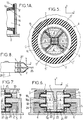
- la figure 1 est une vue en coupe d'un dispositif antivibratoire selon une première forme de réalisation de l'invention, suivant la ligne I-I de la figure 2,
- la figure 1A est une vue de détail de la figure 1,
- la figure 2 est une vue en coupe du dispositif de la figure 1, prise selon la ligne II-II de la figure 1,
- la figure 3 est une autre vue en coupe du dispositif de la figure 1, prise selon la ligne III-III de la figure 2,
- la figure 4 est une vue en élévation du dispositif de la figure 1, selon la direction IV de la figure 3,
- la figure 5 est une vue en coupe similaire à la figure 2, pour une deuxième forme de réalisation de l'invention,
- la figure 6 est une vue en coupe similaire à la figure 1, pour une troisième forme de réalisation de l'invention,
- la figure 7 représente une variante du support antivibratoire de la figure 6, et
- la figure 8 est une vue très schématique illustrant l'utilisation des supports antivibratoires selon l'invention pour le montage de pales d'hélicoptère.
- FIG. 1 is a sectional view of an anti-vibration device according to a first embodiment of the invention, along line II of FIG. 2,
- FIG. 1A is a detailed view of FIG. 1,
- FIG. 2 is a sectional view of the device of FIG. 1, taken along the line II-II of FIG. 1,
- FIG. 3 is another view in section of the device of FIG. 1, taken along line III-III of FIG. 2,
- FIG. 4 is an elevation view of the device of FIG. 1, in the direction IV of FIG. 3,
- FIG. 5 is a sectional view similar to FIG. 2, for a second embodiment of the invention,
- FIG. 6 is a sectional view similar to FIG. 1, for a third embodiment of the invention,
- FIG. 7 represents a variant of the antivibration support of FIG. 6, and
- FIG. 8 is a very schematic view illustrating the use of the anti-vibration supports according to the invention for mounting helicopter blades.
Sur les différentes figures, les mêmes références désignent des éléments identiques ou similaires.In the different figures, the same references designate identical or similar elements.
Dans tous les cas, le dispositif antivibratoire de l'invention est destiné à être interposé entre deux éléments rigides, et comporte :
- une première et une deuxième armatures rigides, respectivement 1, 2, qui sont solidarisables respectivement avec deux éléments rigides à réunir, chaque armature présentant une face d'appui, respectivement 3, 4, dirigée vers l'autre armature rigide, les deux faces d'appui étant disposées en regard l'une de l'autre et perpendiculairement à un premier axe Z,
- au moins un élément lamifié 5 ou 5', interposé entre les deux faces d'appui 3, 4, ledit élément lamifié étant constitué de couches alternées de matériau rigide, notamment métallique, et d'élastomère, qui sont disposées perpendiculairement au premier axe Z.
- a first and a second rigid reinforcement, respectively 1, 2, which can be secured respectively with two rigid elements to be joined, each reinforcement having a bearing face, respectively 3, 4, directed towards the other rigid reinforcement, the two faces d support being arranged opposite one another and perpendicular to a first axis Z,
- at least one laminated
element faces
L'élément lamifié 5 ou 5' présente deux faces opposées qui sont solidaires respectivement des deux armatures 1, 2. Il présente une grande raideur parallèlement à l'axe Z, de sorte que les deux armatures ne peuvent pas se déplacer l'une par rapport à l'autre parallèlement à l'axe Z. Par contre, cet élément lamifié est déformable perpendiculairement à l'axe Z, c'est-à-dire selon deux axes X, Y perpendiculaires à l'axe Z, de sorte qu'un déplacement relatif entre les deux armatures est possible selon les axes X et Y. A titre d'exemple, la déformation des éléments lamifiés selon l'axe Y est représentée en pointillés sur la figure 4 de façon exagérée. La raideur du dispositif selon les axes X et Y est essentiellement déterminée par l'élément lamifié.The
De plus, le dispositif inclut un amortisseur hydraulique, destiné à amortir les vibrations entre les deux armatures dans la direction de l'axe Y. L'amortisseur hydraulique présente dans tous les cas, au moins deux poches étanches A, B, qui sont déformables et reliées par un canal étranglé C, les deux poches étanches et le canal étranglé étant remplis d'un liquide, éventuellement pressurisé.In addition, the device includes a hydraulic damper, intended to dampen the vibrations between the two reinforcements in the direction of the Y axis. The hydraulic damper has in all cases, at least two sealed pockets A, B, which are deformable and connected by a constricted channel C, the two sealed pockets and the constricted channel being filled with a liquid, possibly pressurized.
Les deux poches étanches sont alignées parallèlement à l'axe Y, et chaque poche étanche est délimitée partiellement par une paroi déformable 6 ou 6', qui s'étend entre une première extrémité 6₁ ou 6₁' solidaire de la première armature 1, et une deuxième extrémité 6₂ ou 6₂' solidaire de la deuxième armature 2. Les parois déformables permettent un mouvement relatif des deux armatures parallèlement à l'axe Y.The two sealed pockets are aligned parallel to the Y axis, and each sealed pocket is partially delimited by a
Dans la première forme de réalisation de l'invention, représentée sur les figures 1 à 4, les parois déformables 6 des deux poches étanches A et B sont des parois latérales en forme de tronc de pyramide à base carrée ou rectangulaire, qui s'étendent parallèlement à l'axe Y, depuis leur première extrémité 6₁ jusqu'à leur deuxième extrémité 6₂, en s'élargissant vers leur deuxième extrémité 6₂.In the first embodiment of the invention, shown in FIGS. 1 to 4, the
Les parois déformables 6 sont formées d'une seule pièce dans un corps en élastomère 7, qui présente une partie centrale 8 raccordée de façon étanche à la première extrémité 6₁ desdites parois déformables. Cette partie centrale 8 délimite un logement 8₁ qui s'étend parallèlement à l'axe Z, et qui est ouvert du côté de la première armature 1. Ce logement 8₁ communique avec les deux poches étanches A et B par deux ouvertures 9.The
La première armature 1 comporte une tige de fixation 10, qui est engagée en contact étanche dans le logement 8₁, et le canal étranglé C qui relie les deux poches étanches est un alésage percé dans la tige de fixation 10, qui communique avec les ouvertures 9 du logement 8₁.The first frame 1 comprises a fixing
Pour simplifier les dessins, la tige de fixation 10 a été représentée comme formée d'une seule pièce avec la première armature 1. En réalité, cette tige 10 est une pièce distincte de l'armature 1: le corps en élastomère 7 est d'abord surmoulé sur la tige 10, puis la tige 10 est fixée rigidement à l'armature 1, par exemple par vissage.To simplify the drawings, the fixing
Le corps en élastomère 7 est situé à l'intérieur d'une paroi périphérique rigide 11, qui est solidaire de la deuxième armature 2, et qui s'étend selon l'axe Z à partir de la deuxième armature. Cette paroi périphérique 11, vue en coupe selon un plan perpendiculaire à l'axe Z, comporte deux parties planes en regard 11₁, parallèles à l'axe Y, raccordées latéralement l'une à l'autre par deux parties courbes 11₂ en arc de cercle, la concavité des parties courbes 11₂étant tournée vers l'intérieur de la paroi périphérique.The elastomer body 7 is located inside a rigid
La paroi périphérique rigide 11 est encadrée par deux éléments lamifiés 5, selon l'axe X. Dans l'exemple représenté, ces éléments sont fixés à des embases 20 rigides, elles-mêmes fixées à la face d'appui 4 de la deuxième armature.The rigid
Les parties planes 11₁ de la paroi périphérique rigide 11 constituent des butées qui limitent la déformation des éléments lamifiés 5 parallèlement à l'axe X, et limitent ainsi le déplacement relatif des deux armatures 1 et 2 parallèlement à l'axe X.The flat parts 11₁ of the rigid
La deuxième extrémité 6₂ de chaque paroi déformable 6 est solidaire d'un cadre rigide 12, généralement métallique, et elle forme avec ce cadre un rebord périphérique extérieur 13, sur lequel est sertie une plaque métallique 14 qui ferme ladite deuxième extrémité de la paroi déformable 6.The
Les plaques métalliques 14 ont une forme complémentaire des parties courbes 11₂ de la paroi périphérique rigide 11, et prennent appui sur lesdites parties courbes pour solidariser la deuxième extrémité 6₂ de chaque paroi déformable 6 avec la deuxième armature 2.The
Lorsque la première armature 1 est soumise à des vibrations ou oscillations dans la direction de l'axe Y, le liquide est transféré alternativement d'une poche étanche à l'autre par l'intermédiaire du canal étranglé C. Pour certaines fréquences et amplitudes de vibrations, le canal étranglé C devient le siège de pertes de charge et de phénomènes de résonance qui amortissent considérablement les vibrations, de sorte que lesdites vibrations sont transmises de façon atténuée à la deuxième armature 2.When the first armature 1 is subjected to vibrations or oscillations in the direction of the Y axis, the liquid is transferred alternately from one sealed pocket to the other via the throttled channel C. For certain frequencies and amplitudes of vibrations, the constricted channel C becomes the seat of pressure drops and resonance phenomena which considerably dampen the vibrations, so that said vibrations are transmitted attenuated to the
De plus, les parois déformables 6 ont un effet de rappel élastique de la première armature 1, et participent ainsi à l'amortissement des vibrations, en association avec les éléments lamifiés.In addition, the
La deuxième forme de réalisation de l'invention, représentée sur la figure 5, présente de nombreux points communs avec la première forme de réalisation. Toutefois, le dispositif ne comporte plus deux éléments lamifiés 5, mais un seul élément lamifié 5' de forme annulaire, constitué par un empilement de rondelles constituées alternativement en métal et en élastomère, élément disposé autour de la paroi périphérique rigide 15, qui est ici circulaire.The second embodiment of the invention, shown in Figure 5, has many points in common with the first embodiment. However, the device no longer comprises two
De plus, le corps en élastomère 7 comporte en outre deux poches étanches supplémentaires A' et B', identiques aux poches étanches A et B, mais alignées selon l'axe X.In addition, the elastomer body 7 further comprises two additional waterproof pockets A 'and B', identical to the waterproof pockets A and B, but aligned along the axis X.
Par ailleurs, le logement 8₁ comporte deux ouvertures supplémentaires 9', qui communiquent respectivement avec les deux poches étanches supplémentaires A' et B', et la tige de fixation 10 comporte un deuxième alésage C' percé parallèlement à l'axe X à une hauteur différente de l'alésage C, et qui constitue un canal étranglé supplémentaire communiquant avec les deux poches étanches supplémentaires A' et B' par l'intermédiaire des deux ouvertures supplémentaires 9' du logement 8₁.Furthermore, the
Enfin, chaque poche étanche supplémentaire A',B', est contiguë aux deux poches étanches A et B, et les parois déformables 6 qui délimitent les poches étanches comportent des cloisons radiales 16 qui sont communes à deux chambres contiguës.Finally, each additional waterproof pocket A ′, B ′, is contiguous to the two waterproof pockets A and B, and the
Dans la troisième forme de réalisation de l'invention, représentée sur la figure 6, chaque paroi déformable est une membrane souple 6', qui présente une symétrie de révolution autour de l'axe Y. Cette membrane peut être réalisée par exemple en élastomère renforcé par des fibres, fils ou tissus ou par des anneaux rigides concentriques à l'axe Y. La membrane 6' peut également être réalisée sous la forme d'une paroi mince de métal ou d'un autre matériau à module élastique élevé.In the third embodiment of the invention, shown in FIG. 6, each deformable wall is a
La première armature 1 comporte un corps 21 rigide, qui est situé du côté de la deuxième armature 2, et qui délimite deux chambres cylindriques 22 ayant une forme de révolution autour de l'axe Y. Ces chambres cylindriques 22 sont ouvertes axialement vers l'extérieur, et sont séparées par une cloison 23 plane et perpendiculaire à l'axe Y, dans laquelle est percé un alésage constituant le canal étranglé C.The first frame 1 comprises a
La deuxième armature 2 comporte deux doigts 18 qui s'étendent chacun parallèlement à l'axe Y, entre une première extrémité 18₁ qui est libre et située du côté de la cloison 23, et une deuxième extrémité 18₂ fixée à la deuxième armature 2 par un support vertical 24.The
La première extrémité de chaque membrane souple 6' est un bord périphérique externe 6₁' de ladite membrane, qui est fixé à l'intérieur de l'une des chambres cylindriques 22. En outre, la deuxième extrémité 6₂' de chaque membrane souple est constituée par le centre de ladite membrane, qui est fixée à l'extrémité libre 18₁ d'un des doigts 18.The first end of each flexible membrane 6 'is an outer peripheral edge 6₁' of said membrane, which is fixed inside one of the
Chaque membrane souple 6' forme un pli annulaire 19 autour du doigt 18 correspondant, de sorte que ladite membrane souple 6' permet un débattement important entre les deux armatures 1 et 2 selon l'axe Y. La membrane souple pourrait également avoir une forme de soufflet présentant plusieurs ondes ou plis annulaires, des anneaux rigides de renforcement pouvant éventuellement être prévus au niveau de ces plis.Each flexible membrane 6 'forms an
Comme dans l'exemple de la figure 1, l'amortisseur hydraulique est encadré selon l'axe X par deux éléments lamifiés 5. Comme dans la première forme de réalisation, ceux-ci peuvent se déformer parallèlement à l'axe Y, mais leur déformation parallèlement à l'axe X est limitée par butée contre le corps 21.As in the example in FIG. 1, the hydraulic damper is surrounded along the axis X by two
Cette configuration permet de grands débattements, avec une raideur faible selon l'axe Y, mais une grande résistance à la pression.This configuration allows large deflections, with a low stiffness along the Y axis, but a high resistance to pressure.
Comme représenté sur la figure 7, pour limiter la dilatation de la membrane souple 6' en cours de fonctionnement, où elle est soumise à une pression interne élevée, on peut prévoir un guide annulaire 25 concentrique à chaque doigt 18 et solidaire de la première armature 1, sur la surface intérieure duquel la membrane 6' peut prendre appui, ladite membrane prenant par ailleurs appui sur la surface extérieure du doigt 18.As shown in FIG. 7, in order to limit the expansion of the
Ce guide peut présenter une surface interne cylindrique de révolution, ou bien comportant des ondulations ou autres formes annulaires pour guider la membrane 6'.This guide may have a cylindrical internal surface of revolution, or else comprising corrugations or other annular shapes to guide the
Un montage possible de pales 26 d'hélicoptère dans un rotor 27 d'hélicoptère est donné à titre d'exemple sur la figure 8.A possible mounting of
Dans ce montage, chaque pale d'hélicoptère 26 est fixée aux deuxièmes armatures 2 de deux dispositifs antivibratoires tels que décrits ci-dessus, ces deux dispositifs antivibratoires étant disposés de part et d'autre du plan de la pale 26 et l'axe Y de ces deux dispositifs antivibratoires étant parallèle à la direction longitudinale de la pale 26.In this assembly, each
Par ailleurs, les premières armatures 1 des deux dispositifs antivibratoires sont fixées au moyeu 28 du rotor, qui présente un axe de rotation parallèle à l'axe Z des supports antivibratoires.Furthermore, the first armatures 1 of the two anti-vibration devices are fixed to the
Claims (12)
caractérisé en ce que chaque pale (26) est fixée au moyeu (28) par l'intermédiaire d'au moins un dispositif antivibratoire selon l'une quelconque des revendications précédentes, l'une des armatures (1, 2) de ce dispositif antivibratoire étant liée au moyeu (28) et son autre armature étant liée à la pale (26), le premier axe (Z) du dispositif antivibratoire étant parallèle à l'axe de rotation du moyeu et le deuxième axe (Y) dudit dispositif antivibratoire étant parallèle à l'axe longitudinal de la pale.Helicopter rotor (27) comprising a hub (28) which has an axis of rotation and blades (26) fixed to the hub (28) which each extend along a longitudinal axis substantially perpendicular to the axis of rotation,
characterized in that each blade (26) is fixed to the hub (28) by means of at least one anti-vibration device according to any one of the preceding claims, one of the frames (1, 2) of this anti-vibration device being linked to the hub (28) and its other frame being linked to the blade (26), the first axis (Z) of the anti-vibration device being parallel to the axis of rotation of the hub and the second axis (Y) of said anti-vibration device parallel to the longitudinal axis of the blade.
Applications Claiming Priority (2)
| Application Number | Priority Date | Filing Date | Title |
|---|---|---|---|
| FR9309358 | 1993-07-29 | ||
| FR9309358A FR2708694B1 (en) | 1993-07-29 | 1993-07-29 | Improvement to anti-vibration supports. |
Publications (2)
| Publication Number | Publication Date |
|---|---|
| EP0636810A1 true EP0636810A1 (en) | 1995-02-01 |
| EP0636810B1 EP0636810B1 (en) | 1996-08-21 |
Family
ID=9449766
Family Applications (1)
| Application Number | Title | Priority Date | Filing Date |
|---|---|---|---|
| EP94401730A Expired - Lifetime EP0636810B1 (en) | 1993-07-29 | 1994-07-27 | Improvement for damping supports of helicopter rotor blades and helicopter rotor with such supports |
Country Status (5)
| Country | Link |
|---|---|
| US (1) | US5489193A (en) |
| EP (1) | EP0636810B1 (en) |
| DE (1) | DE69400398T2 (en) |
| FR (1) | FR2708694B1 (en) |
| HK (1) | HK1006740A1 (en) |
Cited By (1)
| Publication number | Priority date | Publication date | Assignee | Title |
|---|---|---|---|---|
| WO2000017047A1 (en) * | 1998-09-23 | 2000-03-30 | Lord Corporation | Fluid damper including flexible damping plate |
Families Citing this family (9)
| Publication number | Priority date | Publication date | Assignee | Title |
|---|---|---|---|---|
| DE19620427C1 (en) * | 1996-05-21 | 1997-06-12 | Eurocopter Deutschland | Rotor blade connection for helicopters |
| GB2317433B (en) * | 1996-09-24 | 2000-09-06 | Draftex Ind Ltd | Vibration damping assemblies |
| FR2839945B1 (en) * | 2002-05-24 | 2004-08-13 | Hutchinson | COMBINED SHOCK ABSORBER DEVICE FOR HELICOPTER ROTOR |
| US6698733B1 (en) * | 2002-12-30 | 2004-03-02 | Paulstra Crc | Hydraulic antivibration support |
| EP2519440B1 (en) * | 2010-02-16 | 2014-12-03 | Bell Helicopter Textron Inc. | Variabale stiffness liquid inertia vibration eliminator |
| US8844429B2 (en) * | 2011-04-01 | 2014-09-30 | G.E.W. International Corporation Limited | Beverage maker with pump noise attenuator |
| FR2984849B1 (en) * | 2011-12-27 | 2013-12-20 | Eurocopter France | LAMINATED TOGETHER, ROTOR WITH SUCH A ROCKET, AND AIRCRAFT |
| US11187047B1 (en) * | 2017-06-26 | 2021-11-30 | Hrl Laboratories, Llc | Multi-degree of freedom vibration isolator |
| CN110469623B (en) * | 2019-08-30 | 2021-10-26 | 株洲时代瑞唯减振装备有限公司 | Forming method of liquid rubber composite node with damping through hole and node |
Citations (11)
| Publication number | Priority date | Publication date | Assignee | Title |
|---|---|---|---|---|
| US3202412A (en) * | 1964-03-06 | 1965-08-24 | Miner Inc W H | Shock attenuating devices |
| DE1625389A1 (en) * | 1961-01-26 | 1970-07-09 | Luxembourg Brev Participations | Elastic, vibration-absorbing mounting |
| DE2921828A1 (en) * | 1978-05-31 | 1979-12-06 | Freyssinet Int Stup | SUPPORT WITH HIGH INNER DAMPING FOR CONSTRUCTION |
| EP0057774A1 (en) * | 1981-02-10 | 1982-08-18 | WOCO Franz-Josef Wolf & Co. | Damper with three chambers |
| EP0097091A1 (en) * | 1982-06-11 | 1983-12-28 | Vibrachoc | Vibration damper, in particular a frequency adapter for helicopter blades |
| EP0134839A2 (en) * | 1983-08-24 | 1985-03-27 | Firma Carl Freudenberg | Hydraulically damped engine support |
| EP0322239A2 (en) * | 1987-12-23 | 1989-06-28 | Avon Industrial Polymers Limited | Hydraulically damped mounting device |
| JPH0246336A (en) * | 1988-08-03 | 1990-02-15 | Toyo Tire & Rubber Co Ltd | Cylinder shaped liquid sealing rubber vibration isolator |
| DE4034573A1 (en) * | 1989-11-01 | 1991-05-02 | Phoenix Ag | Elastic and hydraulically damping bushing - consists of core with outer sleeve and elastomeric piece between, with fluid filled chambers |
| EP0452169A1 (en) * | 1990-03-16 | 1991-10-16 | Hutchinson | Improvements to hydraulic anti-vibration bushes |
| EP0492063A1 (en) * | 1990-12-24 | 1992-07-01 | Boge GmbH | Elastic rubber bearing |
Family Cites Families (12)
| Publication number | Priority date | Publication date | Assignee | Title |
|---|---|---|---|---|
| JPS60172743A (en) * | 1984-02-16 | 1985-09-06 | Kinugawa Rubber Ind Co Ltd | Vibro-isolating bush |
| US4790521A (en) * | 1985-10-03 | 1988-12-13 | Nissan Motor Company, Limited | Anti-vibration apparatus for mounting a power unit on a supporting body with suppression of vibrations |
| FR2590344B1 (en) * | 1985-11-18 | 1989-11-17 | Hutchinson Sa | IMPROVEMENTS ON HYDRAULIC SHOCK ABSORBERS |
| US5042967A (en) * | 1986-09-30 | 1991-08-27 | The Boeing Company | Drive shaft and rotor hub for helicopter flexible rotor system |
| JPH0183944U (en) * | 1987-11-25 | 1989-06-05 | ||
| JPH029343U (en) * | 1988-07-02 | 1990-01-22 | ||
| JP2613641B2 (en) * | 1988-10-24 | 1997-05-28 | ダイニック株式会社 | Spraying foam wallpaper |
| JPH02117450U (en) * | 1989-03-09 | 1990-09-20 | ||
| GB8922338D0 (en) * | 1989-10-04 | 1989-11-22 | Westland Helicopters | Helicopter rotors |
| JPH03176843A (en) * | 1989-12-04 | 1991-07-31 | Ricoh Co Ltd | Optical information recording and reproducing device and recording/erasing pickup and reproducing pickup |
| FR2675869B1 (en) * | 1991-04-23 | 1993-08-13 | Hutchinson | IMPROVEMENTS IN HYDRAULIC ANTI-VIBRATION SLEEVES. |
| DE4117129A1 (en) * | 1991-05-25 | 1992-11-26 | Daimler Benz Ag | Anti-vibration mounting assembly - has four internal chambers which are interconnected and filled with damping fluid |
-
1993
- 1993-07-29 FR FR9309358A patent/FR2708694B1/en not_active Expired - Fee Related
-
1994
- 1994-07-27 EP EP94401730A patent/EP0636810B1/en not_active Expired - Lifetime
- 1994-07-27 DE DE69400398T patent/DE69400398T2/en not_active Expired - Fee Related
- 1994-07-29 US US08/282,017 patent/US5489193A/en not_active Expired - Lifetime
-
1998
- 1998-06-23 HK HK98106092A patent/HK1006740A1/en not_active IP Right Cessation
Patent Citations (11)
| Publication number | Priority date | Publication date | Assignee | Title |
|---|---|---|---|---|
| DE1625389A1 (en) * | 1961-01-26 | 1970-07-09 | Luxembourg Brev Participations | Elastic, vibration-absorbing mounting |
| US3202412A (en) * | 1964-03-06 | 1965-08-24 | Miner Inc W H | Shock attenuating devices |
| DE2921828A1 (en) * | 1978-05-31 | 1979-12-06 | Freyssinet Int Stup | SUPPORT WITH HIGH INNER DAMPING FOR CONSTRUCTION |
| EP0057774A1 (en) * | 1981-02-10 | 1982-08-18 | WOCO Franz-Josef Wolf & Co. | Damper with three chambers |
| EP0097091A1 (en) * | 1982-06-11 | 1983-12-28 | Vibrachoc | Vibration damper, in particular a frequency adapter for helicopter blades |
| EP0134839A2 (en) * | 1983-08-24 | 1985-03-27 | Firma Carl Freudenberg | Hydraulically damped engine support |
| EP0322239A2 (en) * | 1987-12-23 | 1989-06-28 | Avon Industrial Polymers Limited | Hydraulically damped mounting device |
| JPH0246336A (en) * | 1988-08-03 | 1990-02-15 | Toyo Tire & Rubber Co Ltd | Cylinder shaped liquid sealing rubber vibration isolator |
| DE4034573A1 (en) * | 1989-11-01 | 1991-05-02 | Phoenix Ag | Elastic and hydraulically damping bushing - consists of core with outer sleeve and elastomeric piece between, with fluid filled chambers |
| EP0452169A1 (en) * | 1990-03-16 | 1991-10-16 | Hutchinson | Improvements to hydraulic anti-vibration bushes |
| EP0492063A1 (en) * | 1990-12-24 | 1992-07-01 | Boge GmbH | Elastic rubber bearing |
Non-Patent Citations (1)
| Title |
|---|
| PATENT ABSTRACTS OF JAPAN vol. 14, no. 209 (M - 968)<4152> 27 April 1990 (1990-04-27) * |
Cited By (1)
| Publication number | Priority date | Publication date | Assignee | Title |
|---|---|---|---|---|
| WO2000017047A1 (en) * | 1998-09-23 | 2000-03-30 | Lord Corporation | Fluid damper including flexible damping plate |
Also Published As
| Publication number | Publication date |
|---|---|
| FR2708694A1 (en) | 1995-02-10 |
| HK1006740A1 (en) | 1999-03-12 |
| FR2708694B1 (en) | 1995-10-06 |
| US5489193A (en) | 1996-02-06 |
| EP0636810B1 (en) | 1996-08-21 |
| DE69400398D1 (en) | 1996-09-26 |
| DE69400398T2 (en) | 1997-04-03 |
Similar Documents
| Publication | Publication Date | Title |
|---|---|---|
| EP0346227B1 (en) | Modifications of hydraulic antivibration devices | |
| EP0156697B1 (en) | Modifications to hydraulic antivibration mounts | |
| EP0787266B1 (en) | Hydraulic vibration-damping mounting | |
| EP0304349B1 (en) | Hydraulic elastic joint, particularly used for mounting an internal combustion engine in a motor vehicle | |
| EP0636810B1 (en) | Improvement for damping supports of helicopter rotor blades and helicopter rotor with such supports | |
| EP0223712B1 (en) | Modifications of hydraulic dampers | |
| EP0409707B1 (en) | Hydraulic antivibration devices | |
| EP1283377B1 (en) | Hydraulic damping support | |
| EP1136719B1 (en) | Vibration damper, in particular for helicopter rotor | |
| EP1217249A1 (en) | Anti-vibration bush and motor vehicle comprising said bush | |
| EP0646735A1 (en) | Improvements to hydraulical vibration damping supports | |
| EP2113676A1 (en) | Antivibration device, antivibration system comprising such a device and manufacturing process | |
| EP1283376B1 (en) | Hydraulic damping support | |
| EP0875692B1 (en) | Damping device | |
| CA1053642A (en) | Engine bracket | |
| EP0225227A1 (en) | Modifications of hydraulic anti-vibration mountings | |
| EP0097091A1 (en) | Vibration damper, in particular a frequency adapter for helicopter blades | |
| EP0837261B1 (en) | Vibration damper, in particular for helicopter rotor | |
| EP1304498B1 (en) | Hydraulic anti-vibration support | |
| FR2674590A1 (en) | Improvements to hydraulic anti-vibration devices | |
| EP2282076A1 (en) | Anti-vibration device for a vehicle and vehicle including such a device. | |
| EP1293701B1 (en) | Antivibration support and antivibration device comprising the same | |
| FR2787161A1 (en) | Antivibration system e.g. for helicopter transmission unit has elastic ring and resonator connected to its inner surface by two vanes | |
| EP3742018B1 (en) | Hydraulic anti-vibration mounting | |
| EP0497708B1 (en) | Improvements of hydraulic antivibration devices |
Legal Events
| Date | Code | Title | Description |
|---|---|---|---|
| PUAI | Public reference made under article 153(3) epc to a published international application that has entered the european phase |
Free format text: ORIGINAL CODE: 0009012 |
|
| AK | Designated contracting states |
Kind code of ref document: A1 Designated state(s): DE FR GB IT |
|
| 17P | Request for examination filed |
Effective date: 19950123 |
|
| 17Q | First examination report despatched |
Effective date: 19951204 |
|
| GRAH | Despatch of communication of intention to grant a patent |
Free format text: ORIGINAL CODE: EPIDOS IGRA |
|
| GRAH | Despatch of communication of intention to grant a patent |
Free format text: ORIGINAL CODE: EPIDOS IGRA |
|
| GRAA | (expected) grant |
Free format text: ORIGINAL CODE: 0009210 |
|
| AK | Designated contracting states |
Kind code of ref document: B1 Designated state(s): DE FR GB IT |
|
| GBT | Gb: translation of ep patent filed (gb section 77(6)(a)/1977) |
Effective date: 19960823 |
|
| REF | Corresponds to: |
Ref document number: 69400398 Country of ref document: DE Date of ref document: 19960926 |
|
| ITF | It: translation for a ep patent filed |
Owner name: UFFICIO TECNICO ING. A. MANNUCCI |
|
| PLBE | No opposition filed within time limit |
Free format text: ORIGINAL CODE: 0009261 |
|
| STAA | Information on the status of an ep patent application or granted ep patent |
Free format text: STATUS: NO OPPOSITION FILED WITHIN TIME LIMIT |
|
| 26N | No opposition filed | ||
| REG | Reference to a national code |
Ref country code: GB Ref legal event code: IF02 |
|
| PGFP | Annual fee paid to national office [announced via postgrant information from national office to epo] |
Ref country code: FR Payment date: 20090727 Year of fee payment: 16 |
|
| PGFP | Annual fee paid to national office [announced via postgrant information from national office to epo] |
Ref country code: GB Payment date: 20090703 Year of fee payment: 16 Ref country code: DE Payment date: 20090716 Year of fee payment: 16 |
|
| PGFP | Annual fee paid to national office [announced via postgrant information from national office to epo] |
Ref country code: IT Payment date: 20090718 Year of fee payment: 16 |
|
| GBPC | Gb: european patent ceased through non-payment of renewal fee |
Effective date: 20100727 |
|
| REG | Reference to a national code |
Ref country code: FR Ref legal event code: ST Effective date: 20110331 |
|
| PG25 | Lapsed in a contracting state [announced via postgrant information from national office to epo] |
Ref country code: DE Free format text: LAPSE BECAUSE OF NON-PAYMENT OF DUE FEES Effective date: 20110201 |
|
| REG | Reference to a national code |
Ref country code: DE Ref legal event code: R119 Ref document number: 69400398 Country of ref document: DE Effective date: 20110201 |
|
| PG25 | Lapsed in a contracting state [announced via postgrant information from national office to epo] |
Ref country code: FR Free format text: LAPSE BECAUSE OF NON-PAYMENT OF DUE FEES Effective date: 20100802 Ref country code: IT Free format text: LAPSE BECAUSE OF NON-PAYMENT OF DUE FEES Effective date: 20100727 |
|
| PG25 | Lapsed in a contracting state [announced via postgrant information from national office to epo] |
Ref country code: GB Free format text: LAPSE BECAUSE OF NON-PAYMENT OF DUE FEES Effective date: 20100727 |