EP0451991A2 - Système de haut-parleur et TV muni d'un tel système - Google Patents
Système de haut-parleur et TV muni d'un tel système Download PDFInfo
- Publication number
- EP0451991A2 EP0451991A2 EP91302693A EP91302693A EP0451991A2 EP 0451991 A2 EP0451991 A2 EP 0451991A2 EP 91302693 A EP91302693 A EP 91302693A EP 91302693 A EP91302693 A EP 91302693A EP 0451991 A2 EP0451991 A2 EP 0451991A2
- Authority
- EP
- European Patent Office
- Prior art keywords
- speaker
- reproducing
- sound
- frequency sound
- low frequency
- Prior art date
- Legal status (The legal status is an assumption and is not a legal conclusion. Google has not performed a legal analysis and makes no representation as to the accuracy of the status listed.)
- Granted
Links
- 239000011358 absorbing material Substances 0.000 claims description 12
- 239000004020 conductor Substances 0.000 claims description 7
- 230000005855 radiation Effects 0.000 claims description 4
- 230000005236 sound signal Effects 0.000 abstract description 9
- 238000010276 construction Methods 0.000 abstract description 6
- 230000004807 localization Effects 0.000 abstract description 6
- 230000001747 exhibiting effect Effects 0.000 description 3
- 238000013459 approach Methods 0.000 description 1
- 238000010348 incorporation Methods 0.000 description 1
- 238000000034 method Methods 0.000 description 1
- 238000012986 modification Methods 0.000 description 1
- 230000004048 modification Effects 0.000 description 1
- 238000000465 moulding Methods 0.000 description 1
- 230000011514 reflex Effects 0.000 description 1
Images


Classifications
-
- H—ELECTRICITY
- H04—ELECTRIC COMMUNICATION TECHNIQUE
- H04R—LOUDSPEAKERS, MICROPHONES, GRAMOPHONE PICK-UPS OR LIKE ACOUSTIC ELECTROMECHANICAL TRANSDUCERS; DEAF-AID SETS; PUBLIC ADDRESS SYSTEMS
- H04R1/00—Details of transducers, loudspeakers or microphones
- H04R1/20—Arrangements for obtaining desired frequency or directional characteristics
- H04R1/32—Arrangements for obtaining desired frequency or directional characteristics for obtaining desired directional characteristic only
- H04R1/34—Arrangements for obtaining desired frequency or directional characteristics for obtaining desired directional characteristic only by using a single transducer with sound reflecting, diffracting, directing or guiding means
- H04R1/342—Arrangements for obtaining desired frequency or directional characteristics for obtaining desired directional characteristic only by using a single transducer with sound reflecting, diffracting, directing or guiding means for microphones
-
- G—PHYSICS
- G10—MUSICAL INSTRUMENTS; ACOUSTICS
- G10K—SOUND-PRODUCING DEVICES; METHODS OR DEVICES FOR PROTECTING AGAINST, OR FOR DAMPING, NOISE OR OTHER ACOUSTIC WAVES IN GENERAL; ACOUSTICS NOT OTHERWISE PROVIDED FOR
- G10K11/00—Methods or devices for transmitting, conducting or directing sound in general; Methods or devices for protecting against, or for damping, noise or other acoustic waves in general
- G10K11/02—Mechanical acoustic impedances; Impedance matching, e.g. by horns; Acoustic resonators
- G10K11/025—Mechanical acoustic impedances; Impedance matching, e.g. by horns; Acoustic resonators horns for impedance matching
-
- H—ELECTRICITY
- H04—ELECTRIC COMMUNICATION TECHNIQUE
- H04N—PICTORIAL COMMUNICATION, e.g. TELEVISION
- H04N5/00—Details of television systems
- H04N5/64—Constructional details of receivers, e.g. cabinets or dust covers
- H04N5/642—Disposition of sound reproducers
-
- H—ELECTRICITY
- H04—ELECTRIC COMMUNICATION TECHNIQUE
- H04R—LOUDSPEAKERS, MICROPHONES, GRAMOPHONE PICK-UPS OR LIKE ACOUSTIC ELECTROMECHANICAL TRANSDUCERS; DEAF-AID SETS; PUBLIC ADDRESS SYSTEMS
- H04R1/00—Details of transducers, loudspeakers or microphones
- H04R1/20—Arrangements for obtaining desired frequency or directional characteristics
- H04R1/22—Arrangements for obtaining desired frequency or directional characteristics for obtaining desired frequency characteristic only
- H04R1/26—Spatial arrangements of separate transducers responsive to two or more frequency ranges
-
- H—ELECTRICITY
- H04—ELECTRIC COMMUNICATION TECHNIQUE
- H04R—LOUDSPEAKERS, MICROPHONES, GRAMOPHONE PICK-UPS OR LIKE ACOUSTIC ELECTROMECHANICAL TRANSDUCERS; DEAF-AID SETS; PUBLIC ADDRESS SYSTEMS
- H04R5/00—Stereophonic arrangements
- H04R5/02—Spatial or constructional arrangements of loudspeakers
-
- H—ELECTRICITY
- H04—ELECTRIC COMMUNICATION TECHNIQUE
- H04R—LOUDSPEAKERS, MICROPHONES, GRAMOPHONE PICK-UPS OR LIKE ACOUSTIC ELECTROMECHANICAL TRANSDUCERS; DEAF-AID SETS; PUBLIC ADDRESS SYSTEMS
- H04R1/00—Details of transducers, loudspeakers or microphones
- H04R1/20—Arrangements for obtaining desired frequency or directional characteristics
- H04R1/22—Arrangements for obtaining desired frequency or directional characteristics for obtaining desired frequency characteristic only
- H04R1/28—Transducer mountings or enclosures modified by provision of mechanical or acoustic impedances, e.g. resonator, damping means
- H04R1/2807—Enclosures comprising vibrating or resonating arrangements
- H04R1/2811—Enclosures comprising vibrating or resonating arrangements for loudspeaker transducers
Definitions
- the present invention relates to a speaker system which is used for video equipment, such as a TV and audio equipment for automobile and a TV utilizing the speaker system.
- a method for providing a horn or an acoustic pipe in the front of a speaker to introduce sound wave generated by the speaker to an opening of the horn or the acoustic pipe has been widely used since it has advantages by which large sound pressure can be obtained and sound can be transferred in a specific direction in comparision with a case in which no horn or acoustic pipe is used.
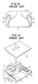
- a prior art speaker system with an acoustic pipe will be described with reference to Figs. 13 to 17.
- Fig. 13 is a plan view illustrating a TV with a pair of middle and low frequency range speaker systems which comprise the prior art speaker systems in which acoustic pipes are used.
- the speaker systems are incorporated into the TV to be located along a cathode tube 4.
- Each of the speaker systems includes a middle and low frequency range reproducing speaker 1 and an acoustic pipe 2 disposed in front thereof for conducting sound wave.
- a TV cabinet 3 of the TV is formed to fit to the speaker systems for miniaturizing the TV in size.
- Fig. 14 is an exploded perspective view showing the construction of the prior art speaker system of Fig. 13.
- reference numeral 5 designates an acoustic equalizer provided at an front portion of the middle and low frequency range reproducing speaker 1.
- Reflection plates 6 are provided outside the apertures 7.
- a sound absorbing material 9 is placed on both sides of the reflection plates 6.
- Each of the acoustic pipes 2 includes a panel 8 and a cover 10 covering an upper open side thereof.
- the acoustic equalizer 5 and the reflection plates 6 which are provided in the front of each of the speakers 1 serve to improve high frequency characteristic of the speaker system.
- the sound absorbing material 9 placed outside the vertical reflection plate 6 serves to suppress a standing wave which is produced within the acoustic pipe 2.
- Each of the acoustic pipe 2 is formed so that the cross-sectional area thereof is gradually increased from the front portion of the middle and low frequency range reproducing speaker 1 toward the open end of the acoustic pipe.
- Figs. 15 and 16 are perspective views showing conventional TVs each utilizing middle and low frequency range reproducing speaker systems with acoustic pipes 2 above described and high frequency range reproducing speakers.
- reference numeral 11 designates an open end of the acoustic pipe of each of the middle and low frequency range reproducing speaker systems
- 12 indicates a high frequency range reproducing speaker arranged above the open end 11.
- each of the high frequency range reproducing speakers 12 is arranged at the front portion of the open end 11 of the corresponding middle and low frequency range reproducing speaker system.
- the high frequency range reproducing speakers 12 are placed at the front of the TV for the following reasons: for the purpose of conducting sound to the opening end portion thereof in a manner similar to that of the middle and low frequency range reproducing speaker system using the acoustic pipe 2, it is necessary to appropriately dispose a sound absorbing material 9 within the acoustic pipe 2 to remove a standing wave generated within the acoustic pipe 2; and the inner construction of the acoustic pipe 2 becomes rather complicated to conduct a high frequency component to the front of the open end 11 without attenuation.
- the TV having the high frequency range reproducing speaker 12 arranged above the middle and low frequency range reproducing speaker 1 as shown in Fig. 15 raises a problem in that sound moves up and down in a middle and high frequency range since the middle and low frequency range reproducing speaker 1 and the high frequency range reproducing speaker 12 are greatly different in mounted position. This deteriorates performance of the speaker systems in sound image localization and articulation of sound, and the speaker systems are not sufficient for an advanced TV.
- the present invention provides a speaker system characterized in that an acoustic pipe for conducting a sound wave is arranged in front of a speaker for reproducing a middle and low frequency sound, the acoustic pipe having a substantially rectangular open end portion, a speaker for reproducing a high frequency sound is disposed within the acoustic pipe coaxially with and in front of the speaker for reproducing the middle and low frequency sound, a sound absorbing material is disposed on opposite sides of the speaker for reproducing the high frequency sound so as to interpose a cavity therebetween, the cavities conducting the sound wave from the speaker for reproducing the middle and low frequency sound, an area of an opening portion in front of the speaker for reproducing the middle and low frequency sound is made smaller as an acoustic equalizer by 20 to 50% than an effective radiation area of the speaker for reproducing the middle and low frequency sound by using a magnetic circuit portion of the speaker for reproducing the high frequency sound, and the opening end portion of the acoustic pipe is larger in area of the sound conductor
- Reflection plates may be disposed on opposite sides of the front portion of the speaker for reproducing the high frequency sound, the reflection plates constituting a sound conductor for conducting a sound wave emitted from the speaker for reproducing the high frequency sound.
- the speaker system thus exhibits excellent characteristics in sound image localization and articulation of sound, thereby providing a high tone quality to the TV.
- the TV may be miniaturized with the speaker system.
- FIGs. 1 to 13 several embodiments of the present invention will be described.
- the same reference numerals as those of Figs. 11 to 14 designate corresponding parts, of which description will be omitted or simplified hereinafter.
- Figs. 1 and 2 illustrate a first embodiment of a speaker system of the present invention, in which an acoustic pipe 2 is arranged in the front of a middle and low frequency range reproducing speaker 1.
- the acoustic pipe 2 has an elongated rectangular front open end 11 which is formed in view of incorporation into a specific appliance.
- a high frequency range reproducing speaker 12 in front of and in the vicinity of the middle and low frequency range reproducing speaker 1 for axial alignment.
- a cavity 14 serves to conduct sound wave of the middle and low frequency range reproducing speaker 1.
- Reflection plates 6 and sound absorbing material 9 are arranged on both sides of the high frequency range reproducing speaker 12 and the cavity 14.
- reference numeral 15 indicates a magnetic circuit portion of the high frequency range reproducing speaker 12, and serves as an acoustic equalizer of the middle and low frequency range reproducing speaker 1. For this reason, the magnetic circuit portion 15 is coaxially closely arranged with the front portion of the middle and low frequency range reproducing speaker 1.
- the cross-sectional or vertical sectional area of the cavity 14 is smaller by about 20 to 50% than an effective radiation area of the middle and low frequency range reproducing speaker 1.
- An open end of the acoustic pipe 2 is formed sufficient large in cross-sectional area as compared to the cavity 14 at the front of the middle and low frequency range reproducing speaker 1.
- the speaker system since the high frequency range reproducing speaker 12 is coaxially and closely arranged in front of the middle and low frequency range reproducing speaker 1, attenuation of middle and low frequency components of sound signals which are produced from the middle and low frequency range reproducing speaker 1 is thus suppressed. Moreover, it is possible to conduct the middle and low frequency components and a high frequency component, which is reproduced by the high frequency range reproducing speaker 12, as naturally composed sound signals to the open and 11 of the acoustic pipe 2. Thus, the speaker system is capable of exhibiting a characteristic with small peak dips as shown in the sound pressure-frequency characteristic curve of the speaker system for a TV in Fig. 3 by reference numeral 16. Furthermore, the problem of which sound moves up and down in a high and middle frequency range is overcome by close coaxial arrangement of the two speakers. This embodiment exhibits an excellent characteristic in sound image localization and in articulation of sound.
- the sound pressure-frequency characteristic of the speaker system of this embodiment largely depends upon the mounted position of the high frequency range reproducing speaker 12. As the mounted position of the high frequency range reproducing speaker 12 approaches toward the open end 11 of the acoustic pipe 2, the speaker system exhibits a sound pressure-frequency characteristic such that sound pressure drops in the middle and high frequency range, and many peak dips take place as shown by the reference numeral 17 in Fig. 3. This is because the magnetic circuit portion 15 of the high frequency range reproducing speaker 12 does not function as the acoustic equalizer for the middle and low frequency range reproducing speaker 1, and because an increase in difference between the mounted position of the two speakers causes the difference in phase between sound waves reproduced from the two speakers in the high and middle frequency range.
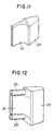
- Fig. 4 illustrates a modified form of the speaker system of Fig. 1.
- the acoustic pipe 18 has an integrally moldable structure which is made by integrally forming the cover 10 with the pipe 2 of the first embodiment.
- the acoustic pipe 18 is provided at one panel portion 18A with a pair of openings 18B at portions corresponding to locations to accommodate the sound absorbing material 9.
- Each of the openings 18B is sealingly covered with a cover plate 19 after the sound absorbing material 9 is placed within the acoustic pipe 18.
- the speaker system is provided with sufficient strength against internal resonance of the acoustic pipe 18. This enables sound distortion produced by the internal resonance of the acoustic pipe 18 to be considerably reduced, and thus the speaker system is enhanced in tone quality. Moreover, the integral molding of the acoustic pipe 18 increases accuracy in size thereof, and it is thereby achieved to reduce in size a TV into which the speaker system of the embodiment is incorporated. The integrally molded structure of the speaker system also enhances productivity of the speaker system and considerably reduces manhours for assembling it.
- Fig. 5 is a perspective view, partly cut away, of a second embodiment of the speaker system of the present invention, in this embodiment, a pair of parallel reflection plates 20 are arranged at respective opposite sides of the high frequency range reproducing speaker 12 in addition to the speaker system shown in Figs. 1 and 2.
- the reflection plates 20 conduct the high frequency component sound wave, reproduced by the high frequency range reproducing speaker 12, to the open end 11 of the acoustic pipe 2.
- a high frequency component which is reproduced by the high frequency range reproducing speaker 12 is conducted to the open end 11 of the acoustic pipe 2 by a sound conductor constituted by the parallel reflection plates 20 disposed in front of the high frequency range reproducing speaker 12.
- the waveform of the high frequency component within the acoustic pipe 2 is not disturbed or not cross modulated by sound wave reproduced from the middle and low frequency range reproducing speaker 1, and thereby sounds reproduced by the speaker system are conducted as sound signals composed in a substantially natural state to the open end 11 of the acoustic pipe 2.
- the speaker system is, accordingly, capable of exhibiting a characteristic having relatively high sound pressure at the middle and high frequency range with small peak dips.
- the problem that sound moves up and down in a high and middle frequency range is overcome by close coaxial arrangement of the two speakers and sound signals reproduced by the speaker system of this embodiment is superior in quality to those reproduced by the speaker system of the first embodiment.
- This embodiment exhibits excellent characteristics in both sound image localization and articulation of sound, which have not been achieved by the prior art.
- Fig. 8 illustrates a modified form of the second embodiment.
- an acoustic pipe 22 has the same structure as the acoustic pipe 2 of Fig. 4 except that the acoustic pipe 22 is provided in an upper panel 22A thereof with a pair of openings 22B at portions corresponding to respective locations to accommodate the sound absorbing material 9.
- Each of the openings 22B is sealingly covered with a cover 23 after the sound absorbing material 9 is placed within the acoustic pipe 22 through the openings 22B. Further detailed description of this modified speaker system is omitted since this modification is identical in structure to the embodiment of Fig. 4 in the other points.
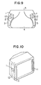
- Figs. 9 and 10 illustrate a TV into which a pair of the first embodiment of the speaker systems of the invention are incorporated.
- Each of the acoustic pipes 2 is placed along a cathode tube 4.
- a TV cabinet 3 is formed so that it fits to each acoustic pipes 2. This construction of the TV achieves miniaturization thereof with ease.
- Fig. 10 is an illustration of a TV having a pair of the speaker systems of the first embodiment incorporated into it so that the open ends 11 of the acoustic pipe 2 of the speaker systems are placed at respective sides of the front of the TV.
- the TV with such a construction also achieves reduction in size, and the accommodated speaker systems enable high tone quality sound signals to be reproduced.
Applications Claiming Priority (4)
| Application Number | Priority Date | Filing Date | Title |
|---|---|---|---|
| JP2086552A JPH0728457B2 (ja) | 1990-03-30 | 1990-03-30 | スピーカ装置およびそれを用いたテレビジョン受像機 |
| JP86552/90 | 1990-03-30 | ||
| JP29236990A JPH0732506B2 (ja) | 1990-10-29 | 1990-10-29 | スピーカ装置およびそれを用いたテレビジョン受像機 |
| JP292369/90 | 1990-10-29 |
Publications (3)
| Publication Number | Publication Date |
|---|---|
| EP0451991A2 true EP0451991A2 (fr) | 1991-10-16 |
| EP0451991A3 EP0451991A3 (en) | 1992-03-18 |
| EP0451991B1 EP0451991B1 (fr) | 1995-08-30 |
Family
ID=26427659
Family Applications (1)
| Application Number | Title | Priority Date | Filing Date |
|---|---|---|---|
| EP91302693A Expired - Lifetime EP0451991B1 (fr) | 1990-03-30 | 1991-03-27 | Système de haut-parleur et TV muni d'un tel système |
Country Status (3)
| Country | Link |
|---|---|
| US (1) | US5229555A (fr) |
| EP (1) | EP0451991B1 (fr) |
| DE (1) | DE69112473T2 (fr) |
Cited By (8)
| Publication number | Priority date | Publication date | Assignee | Title |
|---|---|---|---|---|
| EP0550159A2 (fr) * | 1991-12-05 | 1993-07-07 | Salon Televisiotehdas Oy | Haut-parleur pour poste de télévision |
| DE4220637A1 (de) * | 1992-06-24 | 1994-01-05 | Nokia Deutschland Gmbh | Lautsprecheranordnung für Fernsehgeräte |
| EP0598391A2 (fr) * | 1992-11-18 | 1994-05-25 | Matsushita Electric Industrial Co., Ltd. | Haut-parleur et récepteur de télévision l'incluant |
| EP0744880A1 (fr) * | 1995-05-26 | 1996-11-27 | SANYO ELECTRIC Co., Ltd. | Dispositif de haut-parleur et récepteur de télévision utilisant le même |
| GB2317069A (en) * | 1996-09-06 | 1998-03-11 | Lg Electronics Inc | Loudspeaker system structure for video appliance |
| GB2319924A (en) * | 1996-11-27 | 1998-06-03 | Lg Electronics Inc | Loudspeaker housing for video display appliance |
| EP1039748A2 (fr) * | 1999-03-26 | 2000-09-27 | Aiwa Co., Ltd. | Récepteur de télévision |
| CN115623400A (zh) * | 2022-12-16 | 2023-01-17 | 共达电声股份有限公司 | 一种电子设备 |
Families Citing this family (7)
| Publication number | Priority date | Publication date | Assignee | Title |
|---|---|---|---|---|
| EP0659030B1 (fr) * | 1993-12-16 | 2002-09-18 | Kabushiki Kaisha Toshiba | Haut-parleurs pour postes de télévision |
| GB2302231B (en) * | 1995-03-14 | 1999-01-13 | Matsushita Electric Ind Co Ltd | Speaker system |
| USD384075S (en) * | 1996-05-30 | 1997-09-23 | Sea Light Trading Co., Ltd. | Speaker |
| US6257365B1 (en) * | 1996-08-30 | 2001-07-10 | Mediaphile Av Technologies, Inc. | Cone reflector/coupler speaker system and method |
| WO2002074030A1 (fr) * | 2001-03-07 | 2002-09-19 | Harman International Industries, Inc. | Systeme sonore ayant un cornet hf aligne de maniere coaxiale dans l'embouchure d'un cornet medial |
| CN106231510B (zh) * | 2016-08-25 | 2022-01-25 | 深圳市信维通信股份有限公司 | 一种双声道扬声器 |
| KR102564275B1 (ko) * | 2018-12-17 | 2023-08-07 | 삼성전자주식회사 | 스피커 및 이를 구비한 전자장치 |
Citations (3)
| Publication number | Priority date | Publication date | Assignee | Title |
|---|---|---|---|---|
| FR2245143A1 (en) * | 1973-09-21 | 1975-04-18 | Batlouni Emile | Vented tubular loudspeaker enclosure - has low fundamental resonant frequency and omnidirectional output |
| GB2212694A (en) * | 1987-11-21 | 1989-07-26 | Robert Alfred Webb | Speaker |
| EP0342117A1 (fr) * | 1988-05-06 | 1989-11-15 | Societe Electronique De La Region Pays De Loire | Installation sonore, en particulier stéréophonique pour téléviseurs à haut-parleur intégré de fréquences basses de grandes dimensions |
Family Cites Families (3)
| Publication number | Priority date | Publication date | Assignee | Title |
|---|---|---|---|---|
| US3155774A (en) * | 1960-08-19 | 1964-11-03 | Pye Ltd | Loudspeaker arrangement |
| US4733749A (en) * | 1986-02-26 | 1988-03-29 | Electro-Voice, Inc. | High output loudspeaker for low frequency reproduction |
| NZ225001A (en) * | 1987-06-16 | 1990-09-26 | Matsushita Electric Ind Co Ltd | Loudspeaker: reflected sound waves absorbed |
-
1991
- 1991-03-21 US US07/672,939 patent/US5229555A/en not_active Expired - Fee Related
- 1991-03-27 EP EP91302693A patent/EP0451991B1/fr not_active Expired - Lifetime
- 1991-03-27 DE DE69112473T patent/DE69112473T2/de not_active Expired - Fee Related
Patent Citations (3)
| Publication number | Priority date | Publication date | Assignee | Title |
|---|---|---|---|---|
| FR2245143A1 (en) * | 1973-09-21 | 1975-04-18 | Batlouni Emile | Vented tubular loudspeaker enclosure - has low fundamental resonant frequency and omnidirectional output |
| GB2212694A (en) * | 1987-11-21 | 1989-07-26 | Robert Alfred Webb | Speaker |
| EP0342117A1 (fr) * | 1988-05-06 | 1989-11-15 | Societe Electronique De La Region Pays De Loire | Installation sonore, en particulier stéréophonique pour téléviseurs à haut-parleur intégré de fréquences basses de grandes dimensions |
Cited By (18)
| Publication number | Priority date | Publication date | Assignee | Title |
|---|---|---|---|---|
| EP0550159A2 (fr) * | 1991-12-05 | 1993-07-07 | Salon Televisiotehdas Oy | Haut-parleur pour poste de télévision |
| EP0550159A3 (fr) * | 1991-12-05 | 1994-04-06 | Salon Televisiotehdas Oy | |
| DE4220637A1 (de) * | 1992-06-24 | 1994-01-05 | Nokia Deutschland Gmbh | Lautsprecheranordnung für Fernsehgeräte |
| CN1050491C (zh) * | 1992-11-18 | 2000-03-15 | 松下电器产业株式会社 | 扬声器装置及使用该装置的电视接收机 |
| EP0598391A2 (fr) * | 1992-11-18 | 1994-05-25 | Matsushita Electric Industrial Co., Ltd. | Haut-parleur et récepteur de télévision l'incluant |
| US5455867A (en) * | 1992-11-18 | 1995-10-03 | Matsushita Electric Industrial Co., Ltd. | Speaker apparatus and television receiver using the same |
| EP0598391A3 (fr) * | 1992-11-18 | 1995-03-08 | Matsushita Electric Ind Co Ltd | Haut-parleur et récepteur de télévision l'incluant. |
| EP0748116A1 (fr) * | 1992-11-18 | 1996-12-11 | Matsushita Electric Industrial Co., Ltd. | Haut-parleur pour récepteur de télévision |
| CN1054490C (zh) * | 1995-05-26 | 2000-07-12 | 三洋电机株式会社 | 扬声器装置及采用该装置的电视接收机 |
| EP0744880A1 (fr) * | 1995-05-26 | 1996-11-27 | SANYO ELECTRIC Co., Ltd. | Dispositif de haut-parleur et récepteur de télévision utilisant le même |
| GB2317069B (en) * | 1996-09-06 | 1999-04-07 | Lg Electronics Inc | Dome loudspeaker system structure for video appliance |
| GB2317069A (en) * | 1996-09-06 | 1998-03-11 | Lg Electronics Inc | Loudspeaker system structure for video appliance |
| GB2319924A (en) * | 1996-11-27 | 1998-06-03 | Lg Electronics Inc | Loudspeaker housing for video display appliance |
| GB2319924B (en) * | 1996-11-27 | 1999-02-10 | Lg Electronics Inc | Loudspeaker housing for video display appliance |
| EP1039748A2 (fr) * | 1999-03-26 | 2000-09-27 | Aiwa Co., Ltd. | Récepteur de télévision |
| EP1039748A3 (fr) * | 1999-03-26 | 2001-02-14 | Aiwa Co., Ltd. | Récepteur de télévision |
| CN115623400A (zh) * | 2022-12-16 | 2023-01-17 | 共达电声股份有限公司 | 一种电子设备 |
| CN115623400B (zh) * | 2022-12-16 | 2023-03-17 | 共达电声股份有限公司 | 一种电子设备 |
Also Published As
| Publication number | Publication date |
|---|---|
| EP0451991A3 (en) | 1992-03-18 |
| DE69112473T2 (de) | 1996-05-02 |
| DE69112473D1 (de) | 1995-10-05 |
| US5229555A (en) | 1993-07-20 |
| EP0451991B1 (fr) | 1995-08-30 |
Similar Documents
| Publication | Publication Date | Title |
|---|---|---|
| US5229555A (en) | Speaker system and tv with the same | |
| JP2739835B2 (ja) | 音声会議装置 | |
| US5793000A (en) | Speaker system | |
| EP0429121A1 (fr) | Système de haut-parleurs comportant un résonateur de Helmholtz couplé à un tube acoustique | |
| EP0700210B1 (fr) | Système de haut-parleurs pour un appareil de télévision | |
| KR100202342B1 (ko) | 오디오 또는 비디오 장치 | |
| US7298862B2 (en) | Asymmetrical loudspeaker enclosures with enhanced low frequency response | |
| US5115474A (en) | Speaker system | |
| EP0659030A2 (fr) | Haut-parleurs pour postes de télévision | |
| EP0598391A2 (fr) | Haut-parleur et récepteur de télévision l'incluant | |
| US6343132B1 (en) | Loudspeaker | |
| GB2206262A (en) | Loud speaker | |
| JP3271971B2 (ja) | テレビジョン受像機のスピーカ装置 | |
| JPH0728457B2 (ja) | スピーカ装置およびそれを用いたテレビジョン受像機 | |
| JPH0732506B2 (ja) | スピーカ装置およびそれを用いたテレビジョン受像機 | |
| JP4043539B2 (ja) | スピーカ装置の製造方法 | |
| JP3997649B2 (ja) | スピーカ装置およびこれを用いたテレビジョン受像機 | |
| EP0550159A2 (fr) | Haut-parleur pour poste de télévision | |
| JP3552251B2 (ja) | スピーカ装置およびそれを用いたテレビジョン受像機 | |
| JP3331657B2 (ja) | スピーカ装置およびそれを用いたテレビジョン受像機 | |
| JP2000165974A (ja) | スピーカ装置 | |
| JPH08107594A (ja) | スピーカ装置 | |
| JPH06326948A (ja) | スピーカ装置 | |
| JP2000175281A (ja) | 電子機器のスピーカ装置 | |
| JPH04348698A (ja) | スピーカ装置 |
Legal Events
| Date | Code | Title | Description |
|---|---|---|---|
| PUAI | Public reference made under article 153(3) epc to a published international application that has entered the european phase |
Free format text: ORIGINAL CODE: 0009012 |
|
| AK | Designated contracting states |
Kind code of ref document: A2 Designated state(s): DE GB |
|
| PUAL | Search report despatched |
Free format text: ORIGINAL CODE: 0009013 |
|
| AK | Designated contracting states |
Kind code of ref document: A3 Designated state(s): DE GB |
|
| 17P | Request for examination filed |
Effective date: 19920413 |
|
| 17Q | First examination report despatched |
Effective date: 19940705 |
|
| GRAA | (expected) grant |
Free format text: ORIGINAL CODE: 0009210 |
|
| AK | Designated contracting states |
Kind code of ref document: B1 Designated state(s): DE GB |
|
| REF | Corresponds to: |
Ref document number: 69112473 Country of ref document: DE Date of ref document: 19951005 |
|
| PLBE | No opposition filed within time limit |
Free format text: ORIGINAL CODE: 0009261 |
|
| STAA | Information on the status of an ep patent application or granted ep patent |
Free format text: STATUS: NO OPPOSITION FILED WITHIN TIME LIMIT |
|
| 26N | No opposition filed | ||
| REG | Reference to a national code |
Ref country code: GB Ref legal event code: IF02 |
|
| PGFP | Annual fee paid to national office [announced via postgrant information from national office to epo] |
Ref country code: GB Payment date: 20070321 Year of fee payment: 17 |
|
| PGFP | Annual fee paid to national office [announced via postgrant information from national office to epo] |
Ref country code: DE Payment date: 20070322 Year of fee payment: 17 |
|
| GBPC | Gb: european patent ceased through non-payment of renewal fee |
Effective date: 20080327 |
|
| PG25 | Lapsed in a contracting state [announced via postgrant information from national office to epo] |
Ref country code: DE Free format text: LAPSE BECAUSE OF NON-PAYMENT OF DUE FEES Effective date: 20081001 |
|
| PG25 | Lapsed in a contracting state [announced via postgrant information from national office to epo] |
Ref country code: GB Free format text: LAPSE BECAUSE OF NON-PAYMENT OF DUE FEES Effective date: 20080327 |